EP1835823B1 - Hermetically sealed zip fastener with slider which grips the teeth supporting strips - Google Patents
Hermetically sealed zip fastener with slider which grips the teeth supporting strips Download PDFInfo
- Publication number
- EP1835823B1 EP1835823B1 EP05808848A EP05808848A EP1835823B1 EP 1835823 B1 EP1835823 B1 EP 1835823B1 EP 05808848 A EP05808848 A EP 05808848A EP 05808848 A EP05808848 A EP 05808848A EP 1835823 B1 EP1835823 B1 EP 1835823B1
- Authority
- EP
- European Patent Office
- Prior art keywords
- capsule
- slider
- zip fastener
- strips
- towards
- Prior art date
- Legal status (The legal status is an assumption and is not a legal conclusion. Google has not performed a legal analysis and makes no representation as to the accuracy of the status listed.)
- Expired - Lifetime
Links
Images



Classifications
-
- A—HUMAN NECESSITIES
- A44—HABERDASHERY; JEWELLERY
- A44B—BUTTONS, PINS, BUCKLES, SLIDE FASTENERS, OR THE LIKE
- A44B19/00—Slide fasteners
- A44B19/24—Details
- A44B19/32—Means for making slide fasteners gas or watertight
-
- Y—GENERAL TAGGING OF NEW TECHNOLOGICAL DEVELOPMENTS; GENERAL TAGGING OF CROSS-SECTIONAL TECHNOLOGIES SPANNING OVER SEVERAL SECTIONS OF THE IPC; TECHNICAL SUBJECTS COVERED BY FORMER USPC CROSS-REFERENCE ART COLLECTIONS [XRACs] AND DIGESTS
- Y10—TECHNICAL SUBJECTS COVERED BY FORMER USPC
- Y10T—TECHNICAL SUBJECTS COVERED BY FORMER US CLASSIFICATION
- Y10T24/00—Buckles, buttons, clasps, etc.
- Y10T24/25—Zipper or required component thereof
- Y10T24/2514—Zipper or required component thereof with distinct member for sealing surfaces
-
- Y—GENERAL TAGGING OF NEW TECHNOLOGICAL DEVELOPMENTS; GENERAL TAGGING OF CROSS-SECTIONAL TECHNOLOGIES SPANNING OVER SEVERAL SECTIONS OF THE IPC; TECHNICAL SUBJECTS COVERED BY FORMER USPC CROSS-REFERENCE ART COLLECTIONS [XRACs] AND DIGESTS
- Y10—TECHNICAL SUBJECTS COVERED BY FORMER USPC
- Y10T—TECHNICAL SUBJECTS COVERED BY FORMER US CLASSIFICATION
- Y10T24/00—Buckles, buttons, clasps, etc.
- Y10T24/25—Zipper or required component thereof
- Y10T24/2561—Slider having specific configuration, construction, adaptation, or material
- Y10T24/2563—Slider having specific configuration, construction, adaptation, or material including relatively movable spaced wings [i.e., restraining walls]
Definitions
- the present invention relates to the sector of hermetically sealed zip fasteners, namely those type of zip fasteners which must form an impenetrable barrier preventing the passage of fluids.
- a zip fastener of the type described hitherto in which, however, a first and a second concave capsule having a form which is substantially a mirror-image of each other and arranged with the perimetral edges of their concavities opposite and facing each other are provided on the slider and on opposite sides thereof.
- One of the said capsules has a pin which is perpendicular thereto and able to slide through the slider body and through a hole formed in the other capsule, and the abovementioned gripping member is connected to means which, when they are actuated, cause a simultaneous displacement of both the capsules towards each other in a direction perpendicular to the plane of the zip fastener, with the result that the two strips of elastic material supporting the teeth are gripped between the said capsules with a desired pressure.
- the already described zone where the teeth and slider are joined together, where there is a potential risk of infiltration remains enclosed within the perimetral edges of the abovementioned capsules, which act as a barrier against the passage of a liquid.
- the object of the present invention is therefore to provide a hermetically sealed zip fastener in accordance with that described in the accompanying claims.
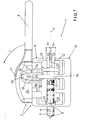
- Figures 1 , 2 , 3 and 4 show a first example of embodiment of the zip fastener 1 according to the invention, comprising a slider 7, with a pull tag 8, which joins together and disengages two rows of teeth 3, 4 which are fixed onto two compressively elastic strips 5, 6 facing each other along one edge thereof, the displacement of the slider 7 in the two directions being obtained by operating the said pull tag 8 in a known manner.
- the said slider 7 is provided, on opposite sides of the said strips 5, 6, with a first concave capsule 10 and a second concave capsule 11 having a form which is substantially a mirror-image of each other and arranged with the perimetral edges 12, 13 of their concavities opposite and facing each other.
- the said first capsule 10 which is shown in the lower position, has a perpendicular pin 14 which is directed upwards and passes through a cavity 15 inside the slider 7 as well as a hole 16 formed in the second capsule, so that the two capsules 10, 11 may slide perpendicularly relative to each other along the abovementioned pin 14.
- the pull tag 8 is keyed integrally onto a spindle 19 which is pivotably mounted at the ends onto a cap 24 forming part of the slider 7 and the pull tag 8 itself has externally a cam surface 17 which makes contact with the upper wall 11s of the said second capsule 11.
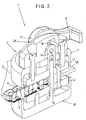
- the abovementioned spindle 19 passes through a transverse hole 20 (see also in this connection the enlarged detail in Figure 3 where the spindle has been omitted for the sake of clarity) formed in a part 14n integral with the free end of the said pin 14 projecting from the first capsule 10 and has at least one section 19t which is also cam-shaped and makes contact with a cavity 18 formed inside the said cap 24.
- This cam-shaped section 19t has dimensions and is shaped such that, for a same rotation Y ( Figures 1 and 2 ) of the pull tag 8, the second capsule 11 is moved towards the first capsule 10 (as a result of rotation of the said cam surface 17) over a distance ⁇ x, equal and opposite to the distance - ⁇ x over which the first capsule 10 moves towards the second capsule 11 as a result of rotation of the abovementioned cam-shaped section 19t.
- Figures 5 and 6 show a second example of embodiment of a zip fastener 2 according to the invention.
- the slider 27 is similar to that described for the previous example and also has a first capsule 10 with spindle 14 and a second capsule 11 through which the said spindle 14 passes.
- the form and the arrangement of the two capsules 10, 11 is entirely similar to that described for the previous example, but the gripping member for moving the slider 27 is a knob 9, which is preferably knurled in order to improve the gripping action and has a cylindrical portion 9c provided with a threaded coaxial hole 25 having a first thread 22 which mates with the threaded free end 14n of the pin 14 projecting from the first capsule 10.
- the abovementioned cylindrical portion 9c also has externally a second thread 21 which has a direction opposite to that of the first thread 22 and which engages inside a threaded hole 23 formed in the second capsule 11, the pitch and direction of the various threads being such that a rotation R of the said knob 9 causes two displacements B, D of the two capsules 10, 11 in an opposite direction, parallel to the axis of the said pin 14, so that they are able to grip between them the strips 5, 6 with a desired pressure, as shown in Figure 6 .
- the inventor envisages forming, on the set or sets of teeth 3, 4 which are situated between the perimetral edges 12, 13 of the capsules 10, 11, grooves 26 able to contain in a complementary manner the end parts 12t, 13t of the said perimetral edges when they have been moved towards each other as fully as possible, namely when the zip fastener 1, 2 has been closed and sealed hermetically by means of gripping of its strips 5, 6 between the capsules 10, 11.
- a further measure envisaged by the inventor for ensuring the hermetic closure of a zip fastener provided in accordance with the invention consists in designing the strips 5, 6 on which the teeth 3, 4 are mounted so that they form a whole, as shown in Figure 4 in connection with the first example, or so that they are hermetically joined together (condition not shown) in the zone Z situated beyond the end part of the zip fastener which is totally occupied by the slider (7 in this case) when the said zip fastener is totally closed.
Landscapes
- Slide Fasteners (AREA)
- Bag Frames (AREA)
- Telephone Set Structure (AREA)
Applications Claiming Priority (2)
| Application Number | Priority Date | Filing Date | Title |
|---|---|---|---|
| CH02107/04A CH697454B1 (it) | 2004-12-20 | 2004-12-20 | Cerniera a tenuta stagna con il cursore che ammorsa i nastri dei denti. |
| PCT/IB2005/003696 WO2006067571A1 (en) | 2004-12-20 | 2005-11-30 | Hermetically sealed zip fastener with slider which grips the teeth supporting strips |
Publications (2)
| Publication Number | Publication Date |
|---|---|
| EP1835823A1 EP1835823A1 (en) | 2007-09-26 |
| EP1835823B1 true EP1835823B1 (en) | 2009-10-14 |
Family
ID=35510814
Family Applications (1)
| Application Number | Title | Priority Date | Filing Date |
|---|---|---|---|
| EP05808848A Expired - Lifetime EP1835823B1 (en) | 2004-12-20 | 2005-11-30 | Hermetically sealed zip fastener with slider which grips the teeth supporting strips |
Country Status (14)
| Country | Link |
|---|---|
| US (1) | US7703182B2 (pl) |
| EP (1) | EP1835823B1 (pl) |
| JP (2) | JP2008523869A (pl) |
| CN (2) | CN100581408C (pl) |
| AT (1) | AT9110U1 (pl) |
| CH (1) | CH697454B1 (pl) |
| DE (2) | DE602005017190D1 (pl) |
| ES (1) | ES1061783Y (pl) |
| FI (1) | FI6999U1 (pl) |
| FR (1) | FR2879413B3 (pl) |
| IT (1) | ITRM20050155U1 (pl) |
| PL (1) | PL378499A1 (pl) |
| TR (1) | TR200505058U (pl) |
| WO (1) | WO2006067571A1 (pl) |
Families Citing this family (7)
| Publication number | Priority date | Publication date | Assignee | Title |
|---|---|---|---|---|
| CH697454B1 (it) * | 2004-12-20 | 2008-10-31 | Riri Group Sa | Cerniera a tenuta stagna con il cursore che ammorsa i nastri dei denti. |
| US20060282994A1 (en) * | 2005-06-14 | 2006-12-21 | Dennis Kupperman | Locking zipper glide device |
| US9545134B1 (en) * | 2015-10-14 | 2017-01-17 | Fu-Hsing Tan | Waterproof zipper |
| CN108606418B (zh) * | 2018-05-29 | 2021-06-04 | 天津浔兴拉链科技有限公司 | 一种便于更换拉链头的拉链 |
| US11363860B2 (en) | 2019-11-23 | 2022-06-21 | Talon Technologies, Inc. | Waterproof curved zippers |
| WO2021100021A1 (en) | 2019-11-23 | 2021-05-27 | Talon Technologies, Inc. | Curved zipper |
| JP7577521B2 (ja) | 2020-11-30 | 2024-11-05 | 住友重機械工業株式会社 | バランサー及び成形装置 |
Family Cites Families (7)
| Publication number | Priority date | Publication date | Assignee | Title |
|---|---|---|---|---|
| GB913113A (en) * | 1959-02-26 | 1962-12-19 | Gandolph Doelter | Improvements relating to sliding clasp fasteners |
| US3376617A (en) * | 1967-04-18 | 1968-04-09 | Pentapco Inc | Separable slider for slide fasteners |
| JPS5441938B2 (pl) * | 1974-05-15 | 1979-12-11 | ||
| JPS59120102A (ja) * | 1982-12-27 | 1984-07-11 | ワイケイケイ株式会社 | スライドフアスナ− |
| JP3659325B2 (ja) * | 2000-10-31 | 2005-06-15 | Ykk株式会社 | 気密・水密性スライドファスナー用スライダー |
| CH695981A5 (it) * | 2002-08-06 | 2006-11-15 | Crelux Holding Sa | Cerniera a tenuta stagna con cursore atto ad ammorsare fra due parti i suoi due nastri. |
| CH697454B1 (it) * | 2004-12-20 | 2008-10-31 | Riri Group Sa | Cerniera a tenuta stagna con il cursore che ammorsa i nastri dei denti. |
-
2004
- 2004-12-20 CH CH02107/04A patent/CH697454B1/it not_active IP Right Cessation
-
2005
- 2005-11-30 WO PCT/IB2005/003696 patent/WO2006067571A1/en not_active Ceased
- 2005-11-30 CN CN200580043810A patent/CN100581408C/zh not_active Expired - Fee Related
- 2005-11-30 EP EP05808848A patent/EP1835823B1/en not_active Expired - Lifetime
- 2005-11-30 JP JP2007546212A patent/JP2008523869A/ja active Pending
- 2005-11-30 US US11/791,956 patent/US7703182B2/en not_active Expired - Fee Related
- 2005-11-30 DE DE602005017190T patent/DE602005017190D1/de not_active Expired - Lifetime
- 2005-12-01 IT IT000155U patent/ITRM20050155U1/it unknown
- 2005-12-02 FR FR0512232A patent/FR2879413B3/fr not_active Expired - Lifetime
- 2005-12-02 DE DE202005018870U patent/DE202005018870U1/de not_active Expired - Lifetime
- 2005-12-14 FI FI20050418U patent/FI6999U1/fi not_active IP Right Cessation
- 2005-12-14 AT AT0086005U patent/AT9110U1/de not_active IP Right Cessation
- 2005-12-16 ES ES200502731U patent/ES1061783Y/es not_active Expired - Fee Related
- 2005-12-16 TR TR2005/05058U patent/TR200505058U/xx unknown
- 2005-12-19 JP JP2005010768U patent/JP3120997U/ja not_active Expired - Fee Related
- 2005-12-20 CN CNU2005201430821U patent/CN2891747Y/zh not_active Expired - Lifetime
- 2005-12-20 PL PL378499A patent/PL378499A1/pl not_active Application Discontinuation
Also Published As
| Publication number | Publication date |
|---|---|
| CN101083922A (zh) | 2007-12-05 |
| PL378499A1 (pl) | 2006-06-26 |
| WO2006067571A1 (en) | 2006-06-29 |
| FR2879413A3 (fr) | 2006-06-23 |
| ITRM20050155U1 (it) | 2006-06-21 |
| FIU20050418U0 (fi) | 2005-12-14 |
| DE602005017190D1 (de) | 2009-11-26 |
| US20080229553A1 (en) | 2008-09-25 |
| JP2008523869A (ja) | 2008-07-10 |
| DE202005018870U1 (de) | 2006-01-19 |
| TR200505058U (tr) | 2006-07-21 |
| ES1061783Y (es) | 2006-07-16 |
| ES1061783U (es) | 2006-04-01 |
| CN100581408C (zh) | 2010-01-20 |
| CN2891747Y (zh) | 2007-04-25 |
| US7703182B2 (en) | 2010-04-27 |
| CH697454B1 (it) | 2008-10-31 |
| HK1115512A1 (zh) | 2008-12-05 |
| EP1835823A1 (en) | 2007-09-26 |
| JP3120997U (ja) | 2006-04-27 |
| FI6999U1 (fi) | 2006-03-08 |
| AT9110U1 (de) | 2007-05-15 |
| FR2879413B3 (fr) | 2006-12-01 |
Similar Documents
| Publication | Publication Date | Title |
|---|---|---|
| JP6692589B2 (ja) | 防水性スライドファスナー | |
| EP1835823B1 (en) | Hermetically sealed zip fastener with slider which grips the teeth supporting strips | |
| US9079008B2 (en) | Medical tube clamp | |
| US7269883B2 (en) | Closure device | |
| JP4993140B2 (ja) | 低摺動パッキンを備えた流体圧機器 | |
| CA2659258A1 (en) | Device for creating a seal between fabrics or other materials | |
| WO2018082131A1 (zh) | 锅盖组件和具有其的烹饪器具 | |
| US20190113151A1 (en) | Safety faucet for hot water | |
| CN108013741B (zh) | 锅盖组件和具有其的烹饪器具 | |
| KR101076451B1 (ko) | 다중 시트를 이용한 양압 밀폐용 삼차 편심 버터플라이 밸브 | |
| US10092376B2 (en) | Orthodontic self-locking bracket | |
| JP2007501367A5 (pl) | ||
| EP0073018B1 (en) | Fluid-tight slide fastener stringer | |
| CN106122509B (zh) | 一种浮动球阀 | |
| EP1394419A2 (en) | Element for indicating valve opening/closure, particularly for hydraulic valve control actuators | |
| JPS6337570Y2 (pl) | ||
| CN217453986U (zh) | 门体结构和机器人 | |
| CN209762291U (zh) | 一种美标闸阀 | |
| KR101387690B1 (ko) | 반도체 설비용 실링부재 | |
| CN210841788U (zh) | 一种防水气密的拉链 | |
| US7225508B2 (en) | Shut apparatus | |
| CN201963927U (zh) | 阀装置 | |
| JPS5911894Y2 (ja) | 密封容器 | |
| RU2243930C2 (ru) | Зажим | |
| CN117345886A (zh) | 一种防垢平板阀 |
Legal Events
| Date | Code | Title | Description |
|---|---|---|---|
| PUAI | Public reference made under article 153(3) epc to a published international application that has entered the european phase |
Free format text: ORIGINAL CODE: 0009012 |
|
| 17P | Request for examination filed |
Effective date: 20070717 |
|
| AK | Designated contracting states |
Kind code of ref document: A1 Designated state(s): DE FR GB IT |
|
| 17Q | First examination report despatched |
Effective date: 20071026 |
|
| RAP1 | Party data changed (applicant data changed or rights of an application transferred) |
Owner name: RIRI GROUP S.A. |
|
| RBV | Designated contracting states (corrected) |
Designated state(s): DE FR GB IT |
|
| RAP1 | Party data changed (applicant data changed or rights of an application transferred) |
Owner name: RIRI GROUP SA |
|
| RAP1 | Party data changed (applicant data changed or rights of an application transferred) |
Owner name: RIRI GROUP SA |
|
| DAX | Request for extension of the european patent (deleted) | ||
| GRAP | Despatch of communication of intention to grant a patent |
Free format text: ORIGINAL CODE: EPIDOSNIGR1 |
|
| GRAS | Grant fee paid |
Free format text: ORIGINAL CODE: EPIDOSNIGR3 |
|
| GRAA | (expected) grant |
Free format text: ORIGINAL CODE: 0009210 |
|
| AK | Designated contracting states |
Kind code of ref document: B1 Designated state(s): DE FR GB IT |
|
| REG | Reference to a national code |
Ref country code: GB Ref legal event code: FG4D |
|
| REF | Corresponds to: |
Ref document number: 602005017190 Country of ref document: DE Date of ref document: 20091126 Kind code of ref document: P |
|
| PLBE | No opposition filed within time limit |
Free format text: ORIGINAL CODE: 0009261 |
|
| STAA | Information on the status of an ep patent application or granted ep patent |
Free format text: STATUS: NO OPPOSITION FILED WITHIN TIME LIMIT |
|
| 26N | No opposition filed |
Effective date: 20100715 |
|
| PGFP | Annual fee paid to national office [announced via postgrant information from national office to epo] |
Ref country code: FR Payment date: 20101210 Year of fee payment: 6 |
|
| PGFP | Annual fee paid to national office [announced via postgrant information from national office to epo] |
Ref country code: DE Payment date: 20101120 Year of fee payment: 6 |
|
| PGFP | Annual fee paid to national office [announced via postgrant information from national office to epo] |
Ref country code: GB Payment date: 20101118 Year of fee payment: 6 Ref country code: IT Payment date: 20101123 Year of fee payment: 6 |
|
| GBPC | Gb: european patent ceased through non-payment of renewal fee |
Effective date: 20111130 |
|
| REG | Reference to a national code |
Ref country code: FR Ref legal event code: ST Effective date: 20120731 |
|
| PG25 | Lapsed in a contracting state [announced via postgrant information from national office to epo] |
Ref country code: IT Free format text: LAPSE BECAUSE OF NON-PAYMENT OF DUE FEES Effective date: 20111130 |
|
| REG | Reference to a national code |
Ref country code: DE Ref legal event code: R119 Ref document number: 602005017190 Country of ref document: DE Effective date: 20120601 |
|
| PG25 | Lapsed in a contracting state [announced via postgrant information from national office to epo] |
Ref country code: GB Free format text: LAPSE BECAUSE OF NON-PAYMENT OF DUE FEES Effective date: 20111130 |
|
| PG25 | Lapsed in a contracting state [announced via postgrant information from national office to epo] |
Ref country code: FR Free format text: LAPSE BECAUSE OF NON-PAYMENT OF DUE FEES Effective date: 20111130 |
|
| PG25 | Lapsed in a contracting state [announced via postgrant information from national office to epo] |
Ref country code: DE Free format text: LAPSE BECAUSE OF NON-PAYMENT OF DUE FEES Effective date: 20120601 |