EP1836062B1 - Attelage de remorquage retractable - Google Patents
Attelage de remorquage retractable Download PDFInfo
- Publication number
- EP1836062B1 EP1836062B1 EP05825945.8A EP05825945A EP1836062B1 EP 1836062 B1 EP1836062 B1 EP 1836062B1 EP 05825945 A EP05825945 A EP 05825945A EP 1836062 B1 EP1836062 B1 EP 1836062B1
- Authority
- EP
- European Patent Office
- Prior art keywords
- tow hitch
- tow
- axis
- holder
- locking
- Prior art date
- Legal status (The legal status is an assumption and is not a legal conclusion. Google has not performed a legal analysis and makes no representation as to the accuracy of the status listed.)
- Expired - Lifetime
Links
Images


Classifications
-
- B—PERFORMING OPERATIONS; TRANSPORTING
- B60—VEHICLES IN GENERAL
- B60D—VEHICLE CONNECTIONS
- B60D1/00—Traction couplings; Hitches; Draw-gear; Towing devices
- B60D1/48—Traction couplings; Hitches; Draw-gear; Towing devices characterised by the mounting
- B60D1/54—Traction couplings; Hitches; Draw-gear; Towing devices characterised by the mounting collapsible or retractable when not in use, e.g. hide-away hitches
-
- B—PERFORMING OPERATIONS; TRANSPORTING
- B60—VEHICLES IN GENERAL
- B60D—VEHICLE CONNECTIONS
- B60D1/00—Traction couplings; Hitches; Draw-gear; Towing devices
- B60D1/01—Traction couplings or hitches characterised by their type
- B60D1/06—Ball-and-socket hitches
-
- B—PERFORMING OPERATIONS; TRANSPORTING
- B60—VEHICLES IN GENERAL
- B60D—VEHICLE CONNECTIONS
- B60D1/00—Traction couplings; Hitches; Draw-gear; Towing devices
- B60D1/48—Traction couplings; Hitches; Draw-gear; Towing devices characterised by the mounting
- B60D1/485—Traction couplings; Hitches; Draw-gear; Towing devices characterised by the mounting mounted by means of transversal members attached to the frame of a vehicle
Definitions
- the invention relates to a retractable tow hitch for passenger cars in particular.
- retractable tow hitches are known.
- the retractable tow hitches are movable between a position of use, in which the tow hitch extends rearward from the car, in longitudinal direction of the car, and a position of storage, shielded from the surroundings, extending in a plane substantially transverse to the longitudinal direction of the car.
- the tow rod is provided with the tow ball at one end and with a nose at the other end.
- the tow rod is provided with sideward projecting stubs that in the position of use, or operative position, are received in recesses arranged in the lower edge of a vertical sleeve which is fixed to the car.
- the tow rod is attached to two vertical suspension rods, which are vertically movable.
- the sleeve is furthermore provided with an aperture for accommodation of the nose.
- the locking nose is released so as to permit the tow rod to tilt downward with its ball end, the stubs moving out of the recesses and the tow hitch being suspended from the suspension rods.
- the tow ball will assume a lowered position, below the level of the bumper of the car.
- the tow hitch is rotated about a vertical axis over 90 degrees, bringing the tow rod into an orientation transverse to the longitudinal direction of the car, in the position of storage.
- the tow rod is held in position by suspension from the suspension rods, allowing the tow rod some freedom of movement in a vertical plane perpendicular to the stubs.
- the tow ball remains at a relatively low level.
- German patent application 10004523 A further embodiment is disclosed in German patent application 10004523 , in which a tow rod provided with a ball is attached to a vertically extending rod, which rod can be rotated about a vertical axis and can be moved up and down by a motor.
- the lower end of the slidable rod must be moved to a level enabling an unhindered passage underneath the bumper during rotation of the tow hitch between an orientation transverse to the longitudinal axis of the car and a rotation parallel to the longitudinal axis of the car.
- the tow rod has a vertically extending mounting portion which is accommodated in a vertical housing secured to the car so as to be slidable up and down as well as to be rotatable about a vertical axis over 90 degrees.
- the tow rod When being moved by operating means from the position of use to the position of storage, the tow rod is lowered, then rotated about an angle of 90 degrees and finally raised.
- the distance over which the tow rod is lowered must be rather large, with the same consequences for the length of the tow rod portion and its vertical guide.
- European patent application 1.090.782 discloses a retractable tow hitch, which is pulled into the position of use and locked therein by means of an electromotor. After release of the locking, the tow hook can be rotated over 90 degrees, about a horizontal axis parallel to the longitudinal axis of the passenger car, into a horizontal orientation. In that position, the tow hook can be lowered to expose a hinge and then be rotated over 90 degrees about a vertical axis so as to bring the tow hook into engagement with a holder for keeping the tow hook in a position of storage. In a preferred embodiment the whole movement of the tow hook between both positions is carried out by the electromotor.
- US 6.712.381 discloses a retractable tow hitch assembly according to the preamble of claim 1.
- the invention provides a tow hitch assembly according to claim 1.
- Such an embodiment enables a simple build-up of an easy-to-use retractable tow hitch assembly.
- the tow hitch member can be transferred from a position of use to a position of storage and vice versa by hand, rendering the construction simple and keeping the manufacturing costs low.
- the pulling forces exerted on the tow hitch member during use can be taken by the locking device, so that the rotational connection of the tow hitch member to the vehicle can be relieved from those pulling forces to a large extent.
- the tow hitch member is connected to the holder device for said movement in a non-motorized manner, preferably by hand and by gravity.
- This embodiment is in particular low-cost and therefore affordable to many users.
- the holder device comprises a holder member which forms part of the holder parts and is to be fixed -directly or indirectly- to the vehicle, and the tow hitch member is attached to the holder member by means of a hinge having more than one axis of rotation, such as a ball hinge.
- the ball hinge may be provided with guide edges for guiding the movement of the tow hitch member during said movement.
- the tow hitch member may be rotatable with respect to the holder parts or the vehicle about a first axis and about a second axis which is at an angle to the first axis, wherein the first axis has a dominant upward directional component, and is preferably substantially vertical and wherein the second axis has a dominant horizontal directional component and is preferably substantially horizontal.
- the holder device comprises a holder member which is rotatable with respect to the vehicle about a first axis and the tow hitch member is rotatable with respect to the holder member about a second axis which is at an angle to the first axis.
- the rotational connection between tow hitch member and vehicle is built up from two or more rotational connections that may be non-coincident, spaced from one another.
- the first axis may have a dominant upward directional component, and is preferably substantially vertical.
- the second axis may have a dominant horizontal directional component and is preferably substantially horizontal.
- the holder member may be elongated and the rotation axis coincides with a longitudinal axis of the elongated holder member.
- the holder device may be provided with fourth locking means arranged for locking cooperation with the second locking means and preferably the third locking means for locking the fourth and second locking means to each other in said second secondary orientation of the tow hitch member, wherein, preferably, the fourth locking means provide a positioning means for the tow hitch member in its second secondary orientation.
- the first and fourth locking means may be oriented substantially transverse to each other, and/or the first and second secondary orientations of the tow hitch member are substantially transverse to each other, corresponding to the position of use and the position of storage.
- the first and fourth locking means comprise holes and the third locking means comprise a locking pin insertable in said holes, wherein preferably the tow hitch bar is provided with a hole forming the second locking means.
- Such a locking pin is easy to handle.
- the tow hitch member may be attached to the holder device at an inner end of the tow hitch member.
- the rotational components may be more easily shielded from the rear side of a passenger car, as the distance from the tow hitch ball will be largest here.
- such a location distal from the tow hitch ball facilitates the handling of the tow hitch member by hand.
- the tow hitch ball in the first secondary orientation is located at a higher level than in a second secondary orientation.
- the tow hitch member in its first secondary orientation the tow hitch member is in its position of use, and in its second secondary orientation the tow hitch member is in its position of storage.
- the holder device is provided with a holder member, wherein holder member is attached to the holder device so as to be rotatable about a rotation axis, the tow hitch member at an inner end thereof being attached to the holder member so as to be hingeable about a hinge axis substantially transverse to the rotation axis.
- the holder member is elongated and the rotation axis coincides with a longitudinal axis of the elongated holder member.
- the hinge axis and the rotation axis may intersect, and/or in the position of use the rotation axis is vertical, and/or the hinge axis is substantially perpendicular to the rotation axis.
- said locking device comprises a hole in the tow hitch member and a locking pin which is insertable in said hole.
- the locking device may comprise a locking member fixedly attached to the vehicle and provided with a hole for passage of the locking pin.
- the locking device may be located between the inner end of the tow hitch member and the tow hitch ball.
- Said more than one axis may intersect at a location which is stationary in vertical level during said movement.
- said locking device is located between the inner end of the tow hitch member and the tow hitch ball.
- the connection between the tow hitch member and the holder device may be a ball hinge.
- the ball hinge may have a housing fixed to the holder device and a ball secured to the tow hitch rod, wherein the housing is provided with one or more guiding edges for guiding the hinging movement of the ball in the housing.
- the ball may be connected to the tow hitch bar, preferably the inner end thereof, by a connector, such as a rod, and the housing has guide edges for the connector.
- the invention provides a passenger car provided with a tow hitch assembly according to the invention.
- the car comprises a rear cross beam, wherein the holder device is attached to the rear cross beam.
- the tow hitch ball is located below the rear cross beam.
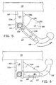
- the tow hitch assembly 1 includes a cross beam or bar 100 which is to be attached to the chassis of a passenger car (not shown) and forms part of a holder device for a tow hitch member 2.
- the tow hitch assembly 1 thus comprises a tow hook (tow hitch member) 2, which at its outer end is provided with a ball 3 which forms a unity with a tow bar or rod 4, which serves to attach the tow hook 2 to fastening means attached to the cross beam or bar 100 and to transfer towing forces exerted on the ball 3 to the cross beam 100 and through the cross beam 100 to the chassis of the vehicle.
- a tow hook tow hitch member 2
- the tow hitch assembly 1 thus comprises a tow hook (tow hitch member) 2, which at its outer end is provided with a ball 3 which forms a unity with a tow bar or rod 4, which serves to attach the tow hook 2 to fastening means attached to the cross beam or bar 100 and to transfer towing forces exerted on the ball 3 to the cross beam 100 and through the cross beam 100 to the chassis of the vehicle.
- a short vertical rod 14 has been attached to the cross beam 100.
- the rod 14 is attached to the cross beam 100 in a rotary-fixed manner by means of nuts 26a and 26b and locking rings (not shown).
- a sleeve or ring 13 has been mounted on a lower portion of the vertical rod 14 extending below the cross beam 100, so as to be freely rotatable about an axis S of the vertical rod 14, supported by nut 26c which is locked on rod 14 ( figure 1B ).
- Two vertical plates 15a, 15b form one fixed unity with the sleeve ring 13, so as to be rotatable therewith about axis S, and form a generally inverted U-shaped member with the sleeve or ring 13.
- the plates 15a, 15b have been provided with aligned holes, through which a horizontally oriented bolt 16 extends, fastened to the plates 15a,b by means of nut 17 and bolt head 18.
- the tow bar 4 has an outer inner end 5, which is provided with a horizontally extending bore or hole 6. As can be seen in figures 1B and 1C , the bolt 16 extends through the hole 6, the tow bar inner end 5 being in part accommodated within a space formed between the plates 15a, 15b.
- the connection of the tow bar inner end 5 to the plates 15a, 15b by means of the bolt 16 is such that the tow bar 4 is rotatable about an axis T of bolt 16 in a vertical plane, with respect to the plates 15a, 15b.
- the lower end plates 11a, 11b have been provided with aligned holes 12a,b, for accommodation of a locking pin 21 of a locking member 20, as can be seen in figure 1A .
- the locking member 20 has been provided with a handle 22 at one end, and with a locking groove 24 at its other end, vide figure 1B .
- a locking spring clamp 23 has been slid transversely over this outer end of the pin 21, accommodated in the groove 24, so that the locking pin 21 is secured against removal.
- the tow bar 4 At a distance from its inner end 5 the tow bar 4 has been provided with a transverse hole 7, which is dimensioned to closely receive the pin 21 when aligned with the holes 12a,b.
- the lower plate 11a has been provided with a plate 30, that is oriented in a vertical plane and, considered in the horizontal plane, is at an angle of 90 degrees to the lower plate 11a.
- the plate 30 slopes downward at an angle of approximately 45 degrees, and is provided with a hole 31, which is dimensioned to closely receive the pin 21, as will be discussed later.
- the tow bar 4 is attached to the rear cross beam 100 (indirectly) at its inner end 5 by hinge pin 16 only.
- the tow bar 4 will be able to cant freely downwards in direction C ( figure 2C ), to a position in which the tow hook 2 rests on a sub surface, in particular the pavement.
- the user can easily take the ball 3 so as to move the tow hook 2 to the position in figure 2D , transverse to the longitudinal axis of the car, in which movement (arrow D) the inner end 5 of the tow bar 4 will be rotated about vertical axis S, about an angle of 90 degrees.
- the user puts his hand below the tow bar 4 and urges the tow hook 2 upward in direction E into the position depicted in figure 2E , in which the tow bar 4 is adjacent the plate 30.
- the user ensures that the hole 7 is aligned with the hole 31 in plate 30, and then takes the handle 22 of locking member 20, and inserts the pin 21 into, first, hole 7 of tow bar 4 and then into hole 31 of plate 30.
- the plate 30 may serve as an abutment for tow rod 4 preventing further rotation of the tow rod 4 about the axis S during the insertion of the pin 21.
- the level of the ball 3 in the position of storage is lower than the level of the ball 3 in the position of use, which is realised by a suitable location of_hole 31 and by suitable location and dimensions of the plate 30.
- the second exemplary embodiment of a tow hitch assembly according to the invention comprises a tow hitch assembly 101, attached to a cross bar 100 which is to be secured to a vehicle (further not shown).
- Two vertical plates 110a,b have been fixedly secured to the beam 100.
- the plates 110a,b define a vertical space 160 in which tow hitch member 102 can be accommodated, in the position of use depicted in figure 3 .
- Tow hitch member 102 comprises a tow hitch ball 103 and a tow bar 104 having an inner end 105.
- the tow bar 104 has been provided with a transverse through-hole 107, which hole 107 can be aligned with holes 112a,b in vertical plates 110a,b.
- a pin 121 is inserted through the holes 112a,b and 107 and secured in that position, in a manner not shown but similar to the securing of the pin 21 in the previous example.
- the plates 110a,b are connected to each other by a transverse, vertical plate 115.
- a bearing housing 132 is fixedly attached to the plate 115, and defines (vide figures 3A-C ) a housing for bearing ball 131, which is fixedly attached to the inner end 105 of tow bar 104 via neck 130.
- the neck or rod 130 extends through a rearward directed opening 134 of bearing housing 132.
- the opening 134 is limited by flanged edge 134a, which extends in a vertical plane, perpendicular to the neck 130.
- the edge 134a is interrupted to leave a passage 135 free.
- the passage 135 merges into opening 136 in the bearing housing 132, which opening 136 is limited by edge 133.
- a plate 150 Fixed to the plate 110a, perpendicular thereto, is a plate 150, which is provided with a hole 151, for accommodation of the pin 121 for storing the tow bar 104 in the position of non-use.
- the user In order to transfer the tow bar 104 from the position of use of figure 3 , via the intermediate positions depicted in figures 4 , 5 and 6 , to a position of non-use (not shown), the user removes the locking pin 121, as a result of which the tow bar 4 will fall downward in direction C.
- the neck 130 passes through the opening 135, the tow bar 4 rotating about a horizontal axis T through the centre of the ball bearing 131/132, guided by the side plates 110a,b.
- This motion of the tow bar 104 can take place under the influence of gravity due to the tow bars 4 own weight.
- the opening 136 allows the tow bar 4 to cant downwards until the tow bar 104 hits the ground. Then, the user can grasp the tow bar 104, and rotate it about, for instance a vertical axis through the centre of the ball bearing 131/132 to a position below the locking plate 150 ( figure 6 ), and then upwards to bring the hole 107 in line with the hole 151, after which the locking pin 121 can be inserted and secured to lock the tow bar 104 in the position of non-use.
- the ball bearing 131/132 permits various other directions of movement, for instance a combined rotation about a vertical axis and a rotation about a horizontal axis T which rotates together with the ball 131.
- the tow hitch assembly according to the invention including the parts for its operation/movement, is located outside the car with all its components, so that no particular provisions inside the car need to be made for mounting and operating the tow hitch assembly.
Landscapes
- Engineering & Computer Science (AREA)
- Transportation (AREA)
- Mechanical Engineering (AREA)
- Body Structure For Vehicles (AREA)
- Agricultural Machines (AREA)
- Fittings On The Vehicle Exterior For Carrying Loads, And Devices For Holding Or Mounting Articles (AREA)
Claims (34)
- Ensemble d'attelage de remorquage (1 ; 101) comprenant un organe d'attelage de remorquage (2 ; 102) comportant une tige d'attelage de remorquage (4 ; 104) et une rotule d'attelage de remorquage (3 ; 103), et un dispositif de retenue (100, 15 ; 115) destiné à l'organe d'attelage de remorquage, dans lequel le dispositif de retenue comprend des parties de retenue (100) qui doivent être fixement montées sur le véhicule, tel qu'une voiture de tourisme, dans lequel l'organe d'attelage de remorquage (2 ; 102) est relié au dispositif de retenue de manière à pouvoir tourner autour de plusieurs axes (S, T) pour un mouvement par rapport aux parties de retenue et au véhicule entre une orientation primaire dans laquelle la rotule d'attelage de remorquage (3 ; 103) a une position basse et au moins une première orientation secondaire et une deuxième orientation secondaire dans lesquelles la rotule d'attelage de remorquage a une position plus haute, l'ensemble comprenant en outre un dispositif de verrouillage pour verrouiller l'organe d'attelage de remorquage dans au moins ladite première orientation secondaire, dans lequel le dispositif de verrouillage est pourvu de moyens d'actionnement pour verrouiller et/ou déverrouiller le dispositif de verrouillage à la main, caractérisé en ce que lesdits plusieurs axes sont en intersection à un emplacement qui est immobile au niveau vertical au cours dudit mouvement, ledit dispositif de verrouillage étant situé entre l'extrémité intérieure de l'organe d'attelage de remorquage et la rotule d'attelage de remorquage, en particulier à un emplacement le long de la tige d'attelage de remorquage, dans lequel le dispositif de verrouillage (21 ; 121) comprend un premier moyen de verrouillage (12 ; 112) qui est fixé au dispositif de retenue, dans lequel le premier moyen de verrouillage comprend deux plaques (10 ; 110) fixement montées sur les parties de retenue, dans lequel les plaques laissent un passage libre vers le haut pour un mouvement de l'organe d'attelage de remorquage (2 ; 110) vers la première position secondaire et à l'écart de celle-ci, dans lequel l'organe d'attelage de remorquage (2 ; 102) est pourvu d'un deuxième moyen de verrouillage (7 ; 107), dans lequel l'ensemble est en outre pourvu d'un troisième moyen de verrouillage (21 ; 121) pour verrouiller le premier moyen de verrouillage et le deuxième moyen de verrouillage l'un à l'autre dans ladite première orientation secondaire de l'organe d'attelage de remorquage.
- Ensemble d'attelage de remorquage (1 ; 101) selon la revendication 1, dans lequel l'organe d'attelage de remorquage (2 ; 102) est relié au dispositif de retenue (100) pour ledit mouvement d'une manière non motorisée, de préférence à la main ou par gravité.
- Ensemble d'attelage de remorquage (101) selon la revendication 1 ou 2, dans lequel le dispositif de retenue (100 ; 115) comprend un organe de retenue (115) qui fait partie des parties de retenue (100) et qui doit être fixement monté sur le véhicule, et l'organe d'attelage de remorquage (2 ; 102) est attaché à l'organe de retenue au moyen d'une charnière (131, 132) ayant plusieurs axes (S, T) de rotation.
- Ensemble d'attelage de remorquage (101) selon la revendication 3, dans lequel la charnière (131, 132) est une charnière à rotule.
- Ensemble d'attelage de remorquage (101) selon la revendication 4, dans lequel la charnière à rotule (131, 132) est pourvue de bords de guidage (133) destinés à guider le mouvement de l'organe d'attelage de remorquage (102) au cours de son mouvement.
- Ensemble d'attelage de remorquage (1 ; 101) selon l'une quelconque des revendications précédentes, dans lequel l'organe d'attelage de remorquage (2 ; 102) peut tourner par rapport aux parties de retenue (100) autour d'un premier axe (S) et autour d'au moins un deuxième axe (T) qui est à un angle par rapport au premier axe, dans lequel le premier axe (S) a une composante directionnelle vers le haut dominante, et est de préférence sensiblement vertical et dans lequel le deuxième axe (T) a une composante directionnelle horizontale dominante et est de préférence sensiblement horizontal.
- Ensemble d'attelage de remorquage (101) selon la revendication 6, dans lequel il y a au moins deux deuxièmes axes (T), qui s'étendent transversalement l'un à l'autre.
- Ensemble d'attelage de remorquage (1) selon la revendication 1, dans lequel le dispositif de retenue (100, 15) comprend un organe de retenue (15) qui peut tourner par rapport aux parties de retenue (100) autour d'un premier axe (S) et l'organe d'attelage de remorquage (2) peut tourner par rapport à l'organe de retenue (15) autour d'un deuxième axe (T) qui est à un angle par rapport au premier axe (S).
- Ensemble d'attelage de remorquage (1) selon la revendication 8, dans lequel le premier axe (S) a une composante directionnelle vers le haut dominante, et est de préférence sensiblement vertical.
- Ensemble d'attelage de remorquage (1) selon la revendication 8 ou 9, dans lequel le deuxième axe (T) a une composante directionnelle horizontale dominante et est de préférence sensiblement horizontal.
- Ensemble d'attelage de remorquage (1) selon la revendication 8, 9 ou 10, dans lequel l'organe de retenue (15) est allongé et dans lequel l'axe de rotation (S) coïncide avec un axe longitudinal de l'organe de retenue allongé.
- Ensemble d'attelage de remorquage (1 ; 101) selon l'une quelconque des revendications précédentes, dans lequel le dispositif de retenue (100, 15 ; 115) est pourvu d'un quatrième moyen de verrouillage (30 ; 151) agencé pour une coopération de verrouillage avec le deuxième moyen de verrouillage (7 ; 107) et de préférence le troisième moyen de verrouillage (21 ; 121) pour verrouiller le quatrième moyen de verrouillage et le deuxième moyen de verrouillage l'un à l'autre dans ladite deuxième orientation secondaire de l'organe d'attelage de remorquage, dans lequel, de préférence, le quatrième moyen de verrouillage fournit un moyen de positionnement pour l'organe d'attelage de remorquage dans sa deuxième orientation secondaire.
- Ensemble d'attelage de remorquage (1 ; 101) selon la revendication 12, dans lequel le premier moyen de verrouillage (12 ; 112) et le quatrième moyen de verrouillage (30 ; 131) sont orientés sensiblement transversalement l'un à l'autre.
- Ensemble d'attelage de remorquage selon la revendication 12 ou 13, dans lequel la première orientation secondaire et la deuxième orientation secondaire de l'organe d'attelage de remorquage sont sensiblement transversales l'une à l'autre.
- Ensemble d'attelage de remorquage (1 ; 101) selon l'une quelconque des revendications 11 à 14, dans lequel le premier moyen de verrouillage (12 ; 112) et le quatrième moyen de verrouillage (30 ; 151) comprennent des trous et le troisième moyen de verrouillage comprend une goupille de verrouillage (21 ; 121) qui peut être insérée dans lesdits trous, dans lequel, de préférence, la barre d'attelage de remorquage (4 ; 104) est pourvue d'un trou formant le deuxième moyen de verrouillage.
- Ensemble d'attelage de remorquage (1 ; 101) selon l'une quelconque des revendications précédentes, dans lequel l'organe d'attelage de remorquage (2 ; 102) est relié, de manière mobile, au dispositif de retenue à une extrémité intérieure (105) de l'organe d'attelage de remorquage.
- Ensemble d'attelage de remorquage (1 ; 101) selon l'une quelconque des revendications précédentes, dans lequel, dans la première orientation secondaire, la rotule d'attelage de remorquage (3 ; 103) est située à un niveau supérieur à celui dans une deuxième orientation secondaire.
- Ensemble d'attelage de remorquage (1 ; 101) selon l'une quelconque des revendications précédentes, dans lequel, dans sa première orientation secondaire, l'organe d'attelage de remorquage (2 ; 102) se trouve à sa position d'utilisation.
- Ensemble d'attelage de remorquage (1 ; 101) selon l'une quelconque des revendications précédentes, dans lequel, dans sa deuxième orientation secondaire, l'organe d'attelage de remorquage (2 ; 102) se trouve à sa position de rangement.
- Ensemble d'attelage de remorquage (1) selon l'une quelconque des revendications précédentes, dans lequel le dispositif de retenue (100, 15) est pourvu d'un organe de retenue (15), dans lequel l'organe de retenue est attaché au dispositif de retenue de manière à pouvoir tourner autour d'un axe de rotation (S), l'organe d'attelage de remorquage (2) à une extrémité intérieure de celui-ci étant attaché à l'organe de retenue (15) de manière à pouvoir basculer autour d'un axe de charnière (T) sensiblement transversal à l'axe de rotation (S).
- Ensemble d'attelage de remorquage (1) selon la revendication 20, dans lequel l'organe de retenue (15) est allongé et dans lequel l'axe de rotation (S) coïncide avec un axe longitudinal de l'organe de retenue allongé.
- Ensemble d'attelage de remorquage (1) selon la revendication 20 ou 21, dans lequel l'axe de charnière (T) et l'axe de rotation (S) sont en intersection.
- Ensemble d'attelage de remorquage (1) selon la revendication 20, 21 ou 22, dans lequel, à la position d'utilisation, l'axe de rotation (S) est vertical.
- Ensemble d'attelage de remorquage selon l'une quelconque des revendications 20 à 23, dans lequel l'axe de charnière (T) est sensiblement perpendiculaire à l'axe de rotation (S).
- Ensemble d'attelage de remorquage (1 ; 101) selon l'une quelconque des revendications précédentes, dans lequel ledit dispositif de verrouillage (21 ; 121) comprend un trou (7 ; 107) dans l'organe d'attelage de remorquage et une goupille de verrouillage (21 ; 121) qui peut être insérée dans ledit trou.
- Ensemble d'attelage de remorquage selon la revendication 25, dans lequel le dispositif de verrouillage (21 ; 121) comprend un organe de verrouillage (10 ; 150) fixement attaché au véhicule et pourvu d'un trou (12 ; 112) pour le passage de la goupille de verrouillage.
- Ensemble d'attelage de remorquage (1 ; 101) selon la revendication 25 ou 26, dans lequel le dispositif de verrouillage est situé entre l'extrémité intérieure de l'organe d'attelage de remorquage et la rotule d'attelage de remorquage.
- Ensemble d'attelage de remorquage (1 ; 101) selon la revendication 25, 26 ou 27, dans lequel lesdits plusieurs axes (S, T) sont en intersection à un emplacement qui est immobile au niveau vertical au cours dudit mouvement.
- Ensemble d'attelage de remorquage (101) selon l'une quelconque des revendications précédentes, dans lequel la liaison entre l'organe d'attelage de remorquage (102) et le dispositif de retenue (115) est une charnière de rotule.
- Ensemble d'attelage de remorquage (101) selon la revendication 4 ou 5, dans lequel la charnière de rotule (131, 132) comporte un logement (132) fixé au dispositif de retenue (100, 115) et une rotule (131) montée sur la tige d'attelage de remorquage (104), dans lequel le logement (132) est pourvu d'un ou plusieurs bords de guidage (133) pour guider le mouvement de basculement de la rotule dans le logement.
- Ensemble d'attelage de remorquage (101) selon la revendication 30, dans lequel la rotule (131) est reliée à la barre d'attelage de remorquage (104), de préférence à l'extrémité intérieure (105) de celle-ci, par un connecteur (130), comme une tige, et le logement comporte des bords de guidage pour le connecteur (130).
- Voiture de tourisme pourvue d'un ensemble d'attelage de remorquage (1 ; 101) selon l'une quelconque des revendications précédentes.
- Voiture de tourisme selon la revendication 32, comprenant une traverse arrière (100), dans laquelle le dispositif de retenue (15 ; 115) est attaché à la traverse arrière.
- Voiture de tourisme selon la revendication 32 ou 33, dans laquelle, dans la deuxième orientation secondaire, la rotule d'attelage de remorquage (3 ; 103) est située au-dessous de la traverse arrière (100).
Applications Claiming Priority (2)
| Application Number | Priority Date | Filing Date | Title |
|---|---|---|---|
| NL1027882 | 2004-12-24 | ||
| PCT/NL2005/000893 WO2006068479A1 (fr) | 2004-12-24 | 2005-12-23 | Attelage de remorquage retractable |
Publications (2)
| Publication Number | Publication Date |
|---|---|
| EP1836062A1 EP1836062A1 (fr) | 2007-09-26 |
| EP1836062B1 true EP1836062B1 (fr) | 2015-09-23 |
Family
ID=34956424
Family Applications (1)
| Application Number | Title | Priority Date | Filing Date |
|---|---|---|---|
| EP05825945.8A Expired - Lifetime EP1836062B1 (fr) | 2004-12-24 | 2005-12-23 | Attelage de remorquage retractable |
Country Status (3)
| Country | Link |
|---|---|
| EP (1) | EP1836062B1 (fr) |
| RU (1) | RU2385235C2 (fr) |
| WO (1) | WO2006068479A1 (fr) |
Cited By (2)
| Publication number | Priority date | Publication date | Assignee | Title |
|---|---|---|---|---|
| EP4108482B1 (fr) * | 2021-06-23 | 2025-04-02 | MVG Metallverarbeitungsgesellschaft mbH | Dispositif d'attelage destiné à être fixé à un arrière d'un véhicule |
| FR3158258A1 (fr) * | 2024-01-11 | 2025-07-18 | Renault S.A.S | Dispositif d’attelage pour véhicule de traction et véhicule le comprenant. |
Families Citing this family (4)
| Publication number | Priority date | Publication date | Assignee | Title |
|---|---|---|---|---|
| DE102013018735A1 (de) * | 2013-11-08 | 2015-05-13 | Westfalia-Automotive Gmbh | Anhängekupplung mit einer Fixiereinrichtung |
| DE102013018771A1 (de) * | 2013-11-08 | 2015-05-13 | Westfalia-Automotive Gmbh | Anhängekupplung mit einer Trägeranordnung |
| DE102015100490A1 (de) | 2015-01-14 | 2016-07-14 | Scambia Holdings Cyprus Limited | Anhängekupplung |
| US11577559B2 (en) | 2020-06-03 | 2023-02-14 | Ford Global Technologies, Llc | Vehicle tow hook |
Family Cites Families (12)
| Publication number | Priority date | Publication date | Assignee | Title |
|---|---|---|---|---|
| DE3666187D1 (en) * | 1985-11-23 | 1989-11-16 | Dickmann Thomas | Towing device for vehicles |
| DE19521896C2 (de) * | 1995-06-16 | 1997-10-16 | Oris Fahrzeugteile Riehle H | Anhängevorrichtung für insbesondere Personenkraftwagen |
| ES2163219T3 (es) * | 1998-04-17 | 2002-01-16 | Ellebi S R L | Dispositivo de remolcado de un vehiculo con un enganche de bola amovible pero automaticamente bloqueable, provisto de una toma de corriente. |
| DE19826618C2 (de) | 1998-06-17 | 2001-05-03 | Peter Rocca | Anhängekupplung |
| EP1090782A3 (fr) | 1999-10-04 | 2002-02-06 | PEKA-Fahrzeugbau GmbH & Co. KG | Dispositif d'attelage pour véhicules automobiles |
| US6712381B1 (en) * | 1999-10-29 | 2004-03-30 | Wing Enterprises, Inc. | Pivoting, underslung, stowaway, hitch mount |
| DE10004523A1 (de) | 2000-02-02 | 2001-08-09 | Fac Frank Abels Consult & Tech | Anhängerkupplung |
| DE10243045B4 (de) * | 2002-09-12 | 2016-01-21 | Westfalia-Automotive Gmbh | Anhängerkupplung |
| DE10243044B4 (de) * | 2002-09-12 | 2016-01-21 | Westfalia-Automotive Gmbh | Anhängerkupplung |
| DE10327706B3 (de) * | 2003-06-20 | 2005-02-17 | Westfalia-Automotive Gmbh & Co. Kg | Hilfskraftbetätigte Anhängekupplung für Kraftfahrzeuge |
| DE102004004501B4 (de) * | 2004-01-22 | 2021-07-01 | ACPS Automotive GmbH | Anhängekupplung |
| DE102004004504A1 (de) * | 2004-01-22 | 2005-08-18 | Oris Fahrzeugteile Hans Riehle Gmbh | Anhängekupplung |
-
2005
- 2005-12-23 EP EP05825945.8A patent/EP1836062B1/fr not_active Expired - Lifetime
- 2005-12-23 RU RU2007128330/11A patent/RU2385235C2/ru not_active IP Right Cessation
- 2005-12-23 WO PCT/NL2005/000893 patent/WO2006068479A1/fr not_active Ceased
Cited By (2)
| Publication number | Priority date | Publication date | Assignee | Title |
|---|---|---|---|---|
| EP4108482B1 (fr) * | 2021-06-23 | 2025-04-02 | MVG Metallverarbeitungsgesellschaft mbH | Dispositif d'attelage destiné à être fixé à un arrière d'un véhicule |
| FR3158258A1 (fr) * | 2024-01-11 | 2025-07-18 | Renault S.A.S | Dispositif d’attelage pour véhicule de traction et véhicule le comprenant. |
Also Published As
| Publication number | Publication date |
|---|---|
| EP1836062A1 (fr) | 2007-09-26 |
| RU2007128330A (ru) | 2009-02-10 |
| RU2385235C2 (ru) | 2010-03-27 |
| WO2006068479A1 (fr) | 2006-06-29 |
Similar Documents
| Publication | Publication Date | Title |
|---|---|---|
| EP2092815B1 (fr) | Barre d'attelage pour tracteur | |
| US5009446A (en) | Self aligning coupling apparatus | |
| US4768803A (en) | Jointed tow bar | |
| US20100289249A1 (en) | Hitch Apparatuses and Methods of Securing Hitch Apparatuses | |
| US4792153A (en) | Trailer hitch | |
| US8276931B2 (en) | Dual tow ball coupling apparatus | |
| CA2363426C (fr) | Dispositif de remorquage enfichable | |
| CN109890631A (zh) | 可拆卸接收器 | |
| US4194755A (en) | Tow bar for vehicles | |
| US20150258866A1 (en) | Off-vehicle trailer hitch coupler lock and assembly | |
| EP1836062A1 (fr) | Attelage de remorquage retractable | |
| CN208085424U (zh) | 高度可调的拖车牵引装置组件 | |
| US20140183840A1 (en) | Interchangeable trailer hitch assembly | |
| US7712763B2 (en) | Trailer hitch receiver lock | |
| US5441295A (en) | Lock assembly for a trailer hitch | |
| US4893829A (en) | Self aligning coupling apparatus | |
| DE102021209013B4 (de) | Kupplungsaufsatz für eine Kugelkopfkupplung eines Kraftfahrzeugs und Verfahren zum Transportieren mindestens eines Transportgutes mittels eines Kupplungsaufsatzes | |
| EP2790484B1 (fr) | Support liaison sur un vehicule ou machine | |
| US8152120B2 (en) | Multipurpose support for attachments mountable to the tow hitch of a vehicle | |
| US20110133432A1 (en) | Hitch assembly with a swivel plate and method for using the same | |
| US7566067B1 (en) | Adjustable trailer hitch | |
| US3722915A (en) | Hitch for coupling agricultural implements to a towing vehicle | |
| DE10104186A1 (de) | Anhängerkupplung | |
| WO2017136886A1 (fr) | Accouplement | |
| DE202019101978U1 (de) | Trageinrichtung |
Legal Events
| Date | Code | Title | Description |
|---|---|---|---|
| PUAI | Public reference made under article 153(3) epc to a published international application that has entered the european phase |
Free format text: ORIGINAL CODE: 0009012 |
|
| 17P | Request for examination filed |
Effective date: 20070724 |
|
| AK | Designated contracting states |
Kind code of ref document: A1 Designated state(s): AT BE BG CH CY CZ DE DK EE ES FI FR GB GR HU IE IS IT LI LT LU LV MC NL PL PT RO SE SI SK TR |
|
| DAX | Request for extension of the european patent (deleted) | ||
| 17Q | First examination report despatched |
Effective date: 20130429 |
|
| GRAP | Despatch of communication of intention to grant a patent |
Free format text: ORIGINAL CODE: EPIDOSNIGR1 |
|
| INTG | Intention to grant announced |
Effective date: 20150408 |
|
| GRAS | Grant fee paid |
Free format text: ORIGINAL CODE: EPIDOSNIGR3 |
|
| GRAA | (expected) grant |
Free format text: ORIGINAL CODE: 0009210 |
|
| RAP1 | Party data changed (applicant data changed or rights of an application transferred) |
Owner name: BRINK TOWING SYSTEMS B.V. |
|
| AK | Designated contracting states |
Kind code of ref document: B1 Designated state(s): AT BE BG CH CY CZ DE DK EE ES FI FR GB GR HU IE IS IT LI LT LU LV MC NL PL PT RO SE SI SK TR |
|
| REG | Reference to a national code |
Ref country code: GB Ref legal event code: FG4D |
|
| REG | Reference to a national code |
Ref country code: CH Ref legal event code: EP |
|
| REG | Reference to a national code |
Ref country code: AT Ref legal event code: REF Ref document number: 751031 Country of ref document: AT Kind code of ref document: T Effective date: 20151015 |
|
| REG | Reference to a national code |
Ref country code: IE Ref legal event code: FG4D |
|
| REG | Reference to a national code |
Ref country code: DE Ref legal event code: R096 Ref document number: 602005047575 Country of ref document: DE |
|
| REG | Reference to a national code |
Ref country code: FR Ref legal event code: PLFP Year of fee payment: 11 |
|
| REG | Reference to a national code |
Ref country code: NL Ref legal event code: MP Effective date: 20150923 |
|
| PG25 | Lapsed in a contracting state [announced via postgrant information from national office to epo] |
Ref country code: GR Free format text: LAPSE BECAUSE OF FAILURE TO SUBMIT A TRANSLATION OF THE DESCRIPTION OR TO PAY THE FEE WITHIN THE PRESCRIBED TIME-LIMIT Effective date: 20151224 Ref country code: LV Free format text: LAPSE BECAUSE OF FAILURE TO SUBMIT A TRANSLATION OF THE DESCRIPTION OR TO PAY THE FEE WITHIN THE PRESCRIBED TIME-LIMIT Effective date: 20150923 Ref country code: LT Free format text: LAPSE BECAUSE OF FAILURE TO SUBMIT A TRANSLATION OF THE DESCRIPTION OR TO PAY THE FEE WITHIN THE PRESCRIBED TIME-LIMIT Effective date: 20150923 Ref country code: FI Free format text: LAPSE BECAUSE OF FAILURE TO SUBMIT A TRANSLATION OF THE DESCRIPTION OR TO PAY THE FEE WITHIN THE PRESCRIBED TIME-LIMIT Effective date: 20150923 |
|
| REG | Reference to a national code |
Ref country code: LT Ref legal event code: MG4D |
|
| REG | Reference to a national code |
Ref country code: AT Ref legal event code: MK05 Ref document number: 751031 Country of ref document: AT Kind code of ref document: T Effective date: 20150923 |
|
| PG25 | Lapsed in a contracting state [announced via postgrant information from national office to epo] |
Ref country code: SE Free format text: LAPSE BECAUSE OF FAILURE TO SUBMIT A TRANSLATION OF THE DESCRIPTION OR TO PAY THE FEE WITHIN THE PRESCRIBED TIME-LIMIT Effective date: 20150923 |
|
| PG25 | Lapsed in a contracting state [announced via postgrant information from national office to epo] |
Ref country code: NL Free format text: LAPSE BECAUSE OF FAILURE TO SUBMIT A TRANSLATION OF THE DESCRIPTION OR TO PAY THE FEE WITHIN THE PRESCRIBED TIME-LIMIT Effective date: 20150923 |
|
| PG25 | Lapsed in a contracting state [announced via postgrant information from national office to epo] |
Ref country code: EE Free format text: LAPSE BECAUSE OF FAILURE TO SUBMIT A TRANSLATION OF THE DESCRIPTION OR TO PAY THE FEE WITHIN THE PRESCRIBED TIME-LIMIT Effective date: 20150923 Ref country code: SK Free format text: LAPSE BECAUSE OF FAILURE TO SUBMIT A TRANSLATION OF THE DESCRIPTION OR TO PAY THE FEE WITHIN THE PRESCRIBED TIME-LIMIT Effective date: 20150923 Ref country code: ES Free format text: LAPSE BECAUSE OF FAILURE TO SUBMIT A TRANSLATION OF THE DESCRIPTION OR TO PAY THE FEE WITHIN THE PRESCRIBED TIME-LIMIT Effective date: 20150923 Ref country code: IS Free format text: LAPSE BECAUSE OF FAILURE TO SUBMIT A TRANSLATION OF THE DESCRIPTION OR TO PAY THE FEE WITHIN THE PRESCRIBED TIME-LIMIT Effective date: 20160123 Ref country code: CZ Free format text: LAPSE BECAUSE OF FAILURE TO SUBMIT A TRANSLATION OF THE DESCRIPTION OR TO PAY THE FEE WITHIN THE PRESCRIBED TIME-LIMIT Effective date: 20150923 Ref country code: IT Free format text: LAPSE BECAUSE OF FAILURE TO SUBMIT A TRANSLATION OF THE DESCRIPTION OR TO PAY THE FEE WITHIN THE PRESCRIBED TIME-LIMIT Effective date: 20150923 |
|
| PG25 | Lapsed in a contracting state [announced via postgrant information from national office to epo] |
Ref country code: BE Free format text: LAPSE BECAUSE OF NON-PAYMENT OF DUE FEES Effective date: 20151231 Ref country code: PL Free format text: LAPSE BECAUSE OF FAILURE TO SUBMIT A TRANSLATION OF THE DESCRIPTION OR TO PAY THE FEE WITHIN THE PRESCRIBED TIME-LIMIT Effective date: 20150923 Ref country code: PT Free format text: LAPSE BECAUSE OF FAILURE TO SUBMIT A TRANSLATION OF THE DESCRIPTION OR TO PAY THE FEE WITHIN THE PRESCRIBED TIME-LIMIT Effective date: 20160125 Ref country code: AT Free format text: LAPSE BECAUSE OF FAILURE TO SUBMIT A TRANSLATION OF THE DESCRIPTION OR TO PAY THE FEE WITHIN THE PRESCRIBED TIME-LIMIT Effective date: 20150923 Ref country code: RO Free format text: LAPSE BECAUSE OF FAILURE TO SUBMIT A TRANSLATION OF THE DESCRIPTION OR TO PAY THE FEE WITHIN THE PRESCRIBED TIME-LIMIT Effective date: 20150923 |
|
| REG | Reference to a national code |
Ref country code: DE Ref legal event code: R097 Ref document number: 602005047575 Country of ref document: DE |
|
| PG25 | Lapsed in a contracting state [announced via postgrant information from national office to epo] |
Ref country code: LU Free format text: LAPSE BECAUSE OF FAILURE TO SUBMIT A TRANSLATION OF THE DESCRIPTION OR TO PAY THE FEE WITHIN THE PRESCRIBED TIME-LIMIT Effective date: 20151223 Ref country code: MC Free format text: LAPSE BECAUSE OF FAILURE TO SUBMIT A TRANSLATION OF THE DESCRIPTION OR TO PAY THE FEE WITHIN THE PRESCRIBED TIME-LIMIT Effective date: 20150923 |
|
| PLBE | No opposition filed within time limit |
Free format text: ORIGINAL CODE: 0009261 |
|
| REG | Reference to a national code |
Ref country code: CH Ref legal event code: PL |
|
| STAA | Information on the status of an ep patent application or granted ep patent |
Free format text: STATUS: NO OPPOSITION FILED WITHIN TIME LIMIT |
|
| 26N | No opposition filed |
Effective date: 20160624 |
|
| PG25 | Lapsed in a contracting state [announced via postgrant information from national office to epo] |
Ref country code: DK Free format text: LAPSE BECAUSE OF FAILURE TO SUBMIT A TRANSLATION OF THE DESCRIPTION OR TO PAY THE FEE WITHIN THE PRESCRIBED TIME-LIMIT Effective date: 20150923 |
|
| REG | Reference to a national code |
Ref country code: IE Ref legal event code: MM4A |
|
| PG25 | Lapsed in a contracting state [announced via postgrant information from national office to epo] |
Ref country code: IE Free format text: LAPSE BECAUSE OF NON-PAYMENT OF DUE FEES Effective date: 20151223 Ref country code: LI Free format text: LAPSE BECAUSE OF NON-PAYMENT OF DUE FEES Effective date: 20151231 Ref country code: CH Free format text: LAPSE BECAUSE OF NON-PAYMENT OF DUE FEES Effective date: 20151231 |
|
| PG25 | Lapsed in a contracting state [announced via postgrant information from national office to epo] |
Ref country code: SI Free format text: LAPSE BECAUSE OF FAILURE TO SUBMIT A TRANSLATION OF THE DESCRIPTION OR TO PAY THE FEE WITHIN THE PRESCRIBED TIME-LIMIT Effective date: 20150923 |
|
| REG | Reference to a national code |
Ref country code: FR Ref legal event code: PLFP Year of fee payment: 12 |
|
| PG25 | Lapsed in a contracting state [announced via postgrant information from national office to epo] |
Ref country code: BE Free format text: LAPSE BECAUSE OF FAILURE TO SUBMIT A TRANSLATION OF THE DESCRIPTION OR TO PAY THE FEE WITHIN THE PRESCRIBED TIME-LIMIT Effective date: 20150923 |
|
| PG25 | Lapsed in a contracting state [announced via postgrant information from national office to epo] |
Ref country code: BG Free format text: LAPSE BECAUSE OF FAILURE TO SUBMIT A TRANSLATION OF THE DESCRIPTION OR TO PAY THE FEE WITHIN THE PRESCRIBED TIME-LIMIT Effective date: 20150923 Ref country code: HU Free format text: LAPSE BECAUSE OF FAILURE TO SUBMIT A TRANSLATION OF THE DESCRIPTION OR TO PAY THE FEE WITHIN THE PRESCRIBED TIME-LIMIT; INVALID AB INITIO Effective date: 20051223 |
|
| PG25 | Lapsed in a contracting state [announced via postgrant information from national office to epo] |
Ref country code: CY Free format text: LAPSE BECAUSE OF FAILURE TO SUBMIT A TRANSLATION OF THE DESCRIPTION OR TO PAY THE FEE WITHIN THE PRESCRIBED TIME-LIMIT Effective date: 20150923 |
|
| PG25 | Lapsed in a contracting state [announced via postgrant information from national office to epo] |
Ref country code: TR Free format text: LAPSE BECAUSE OF FAILURE TO SUBMIT A TRANSLATION OF THE DESCRIPTION OR TO PAY THE FEE WITHIN THE PRESCRIBED TIME-LIMIT Effective date: 20150923 |
|
| REG | Reference to a national code |
Ref country code: FR Ref legal event code: PLFP Year of fee payment: 13 |
|
| PGFP | Annual fee paid to national office [announced via postgrant information from national office to epo] |
Ref country code: FR Payment date: 20171221 Year of fee payment: 13 Ref country code: DE Payment date: 20171211 Year of fee payment: 13 |
|
| PGFP | Annual fee paid to national office [announced via postgrant information from national office to epo] |
Ref country code: GB Payment date: 20171212 Year of fee payment: 13 |
|
| REG | Reference to a national code |
Ref country code: DE Ref legal event code: R119 Ref document number: 602005047575 Country of ref document: DE |
|
| GBPC | Gb: european patent ceased through non-payment of renewal fee |
Effective date: 20181223 |
|
| PG25 | Lapsed in a contracting state [announced via postgrant information from national office to epo] |
Ref country code: DE Free format text: LAPSE BECAUSE OF NON-PAYMENT OF DUE FEES Effective date: 20190702 Ref country code: FR Free format text: LAPSE BECAUSE OF NON-PAYMENT OF DUE FEES Effective date: 20181231 |
|
| PG25 | Lapsed in a contracting state [announced via postgrant information from national office to epo] |
Ref country code: GB Free format text: LAPSE BECAUSE OF NON-PAYMENT OF DUE FEES Effective date: 20181223 |