EP1836412B1 - Vorrichtung zum auflegen/abnehmen eines bandes und verfahren zum installieren/entfernen eines bandes - Google Patents
Vorrichtung zum auflegen/abnehmen eines bandes und verfahren zum installieren/entfernen eines bandes Download PDFInfo
- Publication number
- EP1836412B1 EP1836412B1 EP06709398A EP06709398A EP1836412B1 EP 1836412 B1 EP1836412 B1 EP 1836412B1 EP 06709398 A EP06709398 A EP 06709398A EP 06709398 A EP06709398 A EP 06709398A EP 1836412 B1 EP1836412 B1 EP 1836412B1
- Authority
- EP
- European Patent Office
- Prior art keywords
- belt
- cylindrical body
- pulley
- shaped device
- annular neck
- Prior art date
- Legal status (The legal status is an assumption and is not a legal conclusion. Google has not performed a legal analysis and makes no representation as to the accuracy of the status listed.)
- Expired - Lifetime
Links
Images

Classifications
-
- F—MECHANICAL ENGINEERING; LIGHTING; HEATING; WEAPONS; BLASTING
- F16—ENGINEERING ELEMENTS AND UNITS; GENERAL MEASURES FOR PRODUCING AND MAINTAINING EFFECTIVE FUNCTIONING OF MACHINES OR INSTALLATIONS; THERMAL INSULATION IN GENERAL
- F16H—GEARING
- F16H7/00—Gearings for conveying rotary motion by endless flexible members
- F16H7/24—Equipment for mounting belts, ropes, or chains
Definitions
- the invention relates to the assembly and disassembly of a belt in a cylindrical body of revolution such as a pulley.
- the invention is particularly applicable to the installation and removal of belts used in motor vehicles.
- a flexible transmission means such as a belt or a chain.
- This belt or chain must be tensioned, for example by means of a tensioner.
- This tensioner can be fixed, and then adjusted after the installation of the belt or chain is dynamic, to allow a variation of the voltage depending on the work that is performed by the machine.
- an action on it allows to release the stress of tension exerted on the belt or chain to allow the introduction - or removal - thereof.
- this object is achieved by a U-shaped device suitable for fitting the groove laterally so that one of the branches of the U temporarily covers a circumferential sector of the pulley.
- the device is not intended to ride the pulley so that the base of the U covers a circumferential sector but to be placed laterally, the covering area being constituted by one of the branches of the U.
- the two cheeks are movable relative to each other and are associated at the base of the U, by at least one tenon.
- the device according to the invention also makes it possible to modify the path of the belt so as to pull it out of the annular groove in which it is housed in order to mount it at the circumference of the cylindrical body. Once mounted at this radial level, the belt can be moved axially to remove it.
- the device according to the invention is particularly intended for garages and is adapted to interventions on the so-called transmission belt that connects the crankshaft to the valve control shaft or the so-called accessory belt. For as much, it can also find application for the assembly or disassembly of any belt in a ring groove.
- the term "cylindrical body of revolution” means both pulleys that axes or rods having an annular groove for housing the belt when it is placed.
- the object of the invention is also achieved by a method of laying a belt on the annular groove of a cylindrical body comprising the introduction of a U-shaped device for covering the annular groove on a circumferential sector of the cylindrical body using one of the branches of the U, the engagement of the belt on said limb and on another cylindrical body intended to be connected to the first by the belt, the alignment of the belt on the annular grooves of the two bodies cylindrical, the rotation of the cylindrical bodies until the branch of the U-shaped device is disengaged from the belt and the withdrawal of the U-shaped device.
- the invention also relates to a method of depositing a belt housed in the annular groove of cylindrical bodies of revolution comprising the introduction of a U-shaped device, so that one of the branches of the U covers the annular groove. on a circumferential sector of the cylindrical body not occupied by the belt, the rotation of the cylindrical bodies until the belt is engaged on said leg of the U, the removal of the belt and the withdrawal of the U-shaped device.
- the methods respectively of laying or depositing a belt according to the invention are implemented using a device for laying and for depositing a belt as described above.
- the invention thus allows the installation and removal of elastic belts without damaging them and with a stretch remaining largely within the elastic limits. Thus, it is no longer necessary, at each occasion of removal of a belt, to replace it with a new belt.
- each type of elastic belt can cover a wider range of belt transmission architectures, which makes this invention solution also very economical and in particular standard.
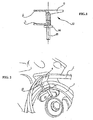
- FIG. 1 shows, in section, a device according to a first variant of the invention not claimed
- the figure 2 shows, in perspective, the device of the figure 1 when laying a belt on a pulley
- the figure 3 shows in perspective, a device according to the invention.
- the device is intended to allow the mounting of an elastic belt C in the groove of a perforated pulley 1 as illustrated. figure 1 .
- the device has the general shape of a U-shaped tool and comprises two cheeks 4 and 5.
- the cheek 4 - still called cover cheek comes temporarily cover a circumferential sector of the groove of the pulley.
- “Temporarily” means: for the installation or removal of the belt.
- the cheek 4 is made in one piece in the shape of an L.
- the cheek 5 represented in FIGS. Figures 1 and 2 is T-shaped, with a retaining tab 9 which makes it possible to prevent the belt C, when it has emerged from the groove of the pulley, from being pushed for example between the pulley and the machine on which the pulley is mounted .
- the two cheeks are mounted movable relative to each other on a rod 61.
- this rod is at least partially threaded and is part of a clamping means 6 which also belongs to a wheel 64 engaged on the rod 61.
- the wheel 64 can be replaced for example by a traditional hexagonal nut or a wing nut.
- the length of the rod is determined so as to ensure a sufficiently long stroke to the wheel to be able to perform the clamping function within the predetermined spacing of the flanges 4, 5.
- the cheek 4 is like the cheek 5 L-shaped, the base of the U being relatively enlarged.
- This variant allows housing in the base not only a threaded rod but also at least one pin 62, associated with the cheek 5 which cooperates with a housing provided in the cheek 4.
- the tenon can be replaced by a sliding rod, in which case a housing will also be provided in the cheek 5.
- the device according to the invention has the advantage of being able to be used for many pulleys within a range of predetermined diameters and widths.
- the cheek 4 has a substantially flat outer surface or, preferably, curved. This cheek 4 forms a stable support for the belt, regardless of the spacing of the cheeks.
- the length of the outer surface of the cheek 4, in the direction of the periphery of the pulley, can be determined so as to cover a circumferential sector of the pulley of the order of 10 ° to 20 °. When the outer surface is curved, the radius of this curvature may correspond approximately to the radius of the pulley.
- the device 10 may exert harmful forces on the belt C by the front and rear edges, in the direction of the periphery of the pulley, at the moment when the device pushes the belt towards the outside.
- the radius defining the curvature of the bearing surface 34 of the device 10 is less than the radius of the pulley, an order of magnitude of 10 to 15%, the central portion of this surface may exert very large forces on the belt when it is pushed outward.
- the method of laying a belt on a cylindrical body of revolution will be implemented. the following way: the annular groove of a cylindrical body 1 is covered over a circumferential sector thereof by means of a cheek 4 by installing a tool 10; the cylindrical body 1 chosen is generally one of the cylindrical bodies to be connected by the belt, which has the largest diameter; however, one can also choose another cylindrical body among them without departing from the principle of the present invention.
- a belt C is then engaged on the outer surface of the cheek 4 and on the other cylindrical body (s) intended to be connected (s) to the first cylindrical body by the belt.
- the belt is aligned on the annular grooves 2 of the cylindrical bodies to be connected and the cylindrical bodies are rotated until the cover flap 4 is released from the belt and withdraws the tool to disengage the annular groove.
- the method of removing a belt from a cylindrical body of revolution will be implemented in the following manner: the annular groove 2 is covered with a first cylindrical body 1 connected to another cylindrical body by a belt C, on a circumferential sector not occupied by the belt, using a cheek 4. The cylindrical body 1 is rotated until the belt is engaged on the cover cheek 4. The belt is removed from the belt cheek 4 and remove or retract the cheek 4.
Landscapes
- Engineering & Computer Science (AREA)
- General Engineering & Computer Science (AREA)
- Mechanical Engineering (AREA)
- Devices For Conveying Motion By Means Of Endless Flexible Members (AREA)
- Storage Of Web-Like Or Filamentary Materials (AREA)
- Load-Engaging Elements For Cranes (AREA)
- Structure Of Belt Conveyors (AREA)
- Paper (AREA)
Claims (5)
- Vorrichtung (10) zum Aufziehen und Abziehen eines Riemens (C) auf bzw. von einem drehzylindrischen Körper (1), umfassend eine gelochte Felge und eine ringförmige Auskehlung zur Aufnahme des aufgezogenen Riemens, wobei diese Vorrichtung aus einem U besteht, das zwei Backen (4, 5) umfasst, die es ermöglichen, die Seite der Auskehlung zu beziehen, so dass die Backe (4) oder die Abdeckbacke (4) die ringförmige Auskehlung auf einem Umfangssektor des zylindrischen Körpers zeitweilig bedeckt, wobei die beiden Backen im Verhältnis zueinander beweglich und L-förmig sind und an der Basis des U durch mindestens einen Stift (62) verbunden sind.
- Vorrichtung nach Anspruch 1, dadurch gekennzeichnet, dass sie mindestens einen Gleitstab (7) und Klemmmittel (6) umfasst.
- Vorrichtung nach einem der vorhergehenden Ansprüche, dadurch gekennzeichnet, dass der Abdeckschenkel (4) eine gekrümmte äußere Oberfläche umfasst.
- Verfahren zum Aufziehen eines Riemens auf einen zylindrischen Körper, der eine ringförmige Auskehlung umfasst, die dazu bestimmt ist, den aufgezogenen Riemen aufzunehmen, umfassend die folgenden Schritte:a) Anbringen einer U-förmigen Vorrichtung (10), um die ringförmige Auskehlung auf einem Umfangssektor des zylindrischen Körpers mit Hilfe eines der U-Schenkel zu bedecken;b) Aufschieben des Riemens (C) auf den Schenkel und auf einen anderen zylindrischen Körper, der dazu bestimmt ist, mit dem ersten durch den Riemen verbunden zu werden;c) Ausrichten des Riemens (C) auf den ringförmigen Auskehlungen (2) der beiden zylindrischen Körper (1),d) Drehen der zylindrischen Körper (1), bis der Schenkel der U-förmigen Vorrichtung von dem Riemen befreit ist; unde) Abnehmen der U-förmigen Vorrichtung (10).
- Verfahren zum Abziehen eines Riemens, der in der ringförmigen Auskehlung (2) eines drehzylindrischen Körpers aufgenommen ist, umfassend die folgenden Schritte:a) Anbringen einer U-förmigen Vorrichtung (10), so dass einer der U-Schenkel die ringförmige Auskehlung (2) auf einem Umfangssektor eines zylindrischen Körpers (1), der nicht von dem Riemen besetzt ist, bedeckt;b) Drehen der zylindrischen Körper (1), bis der Riemen (C) auf den U-Schenkel aufgeschoben ist;c) Entfernen des Riemens (C); undd) Abnehmen der U-förmigen Vorrichtung (10).
Applications Claiming Priority (2)
| Application Number | Priority Date | Filing Date | Title |
|---|---|---|---|
| FR0500271A FR2880572B1 (fr) | 2005-01-11 | 2005-01-11 | Dispositif pour poser et deposer une courroie et procede respectivement de pose et de depose d'une courroie |
| PCT/FR2006/050010 WO2006075113A1 (fr) | 2005-01-11 | 2006-01-10 | Dispositif pour poser et deposer une courroie et procede respectivement de pose et de depose d'une courroie |
Publications (2)
| Publication Number | Publication Date |
|---|---|
| EP1836412A1 EP1836412A1 (de) | 2007-09-26 |
| EP1836412B1 true EP1836412B1 (de) | 2011-06-22 |
Family
ID=34953448
Family Applications (1)
| Application Number | Title | Priority Date | Filing Date |
|---|---|---|---|
| EP06709398A Expired - Lifetime EP1836412B1 (de) | 2005-01-11 | 2006-01-10 | Vorrichtung zum auflegen/abnehmen eines bandes und verfahren zum installieren/entfernen eines bandes |
Country Status (5)
| Country | Link |
|---|---|
| EP (1) | EP1836412B1 (de) |
| AT (1) | ATE514018T1 (de) |
| ES (1) | ES2367317T3 (de) |
| FR (1) | FR2880572B1 (de) |
| WO (1) | WO2006075113A1 (de) |
Families Citing this family (5)
| Publication number | Priority date | Publication date | Assignee | Title |
|---|---|---|---|---|
| CN104033566A (zh) * | 2014-05-19 | 2014-09-10 | 华国洋 | 一种立式转床用皮带轮组件 |
| CN107855977B (zh) * | 2017-12-08 | 2023-07-18 | 苏州宝特威机电有限公司 | 发动机弹性皮带的线下手动安装工装 |
| DE102018128155B3 (de) * | 2018-11-12 | 2020-03-12 | Schaeffler Technologies AG & Co. KG | Greifwerkzeug mit zwei Arten von Greifelementen zum Aufnehmen/Ablegen eines Umschlingungsmittels sowie entsprechendes Verfahren |
| CN113753490B (zh) * | 2021-08-31 | 2023-08-15 | 新兴铸管股份有限公司 | 一种快速更换宽皮带的方法 |
| CN116638477A (zh) * | 2023-06-27 | 2023-08-25 | 广西柳州钢铁集团有限公司 | Npt5型空气压缩机冷却风扇皮带快速拆装方法 |
Family Cites Families (13)
| Publication number | Priority date | Publication date | Assignee | Title |
|---|---|---|---|---|
| DE461460C (de) * | 1928-06-22 | I G Farbenindustrie Akt Ges | Am Riemenscheibenkranz loesbar zu befestigender Riemenaufleger | |
| US685926A (en) * | 1901-06-07 | 1901-11-05 | Heinrich Mundlos | Means for placing bands or the like on pulleys. |
| US774576A (en) * | 1903-07-22 | 1904-11-08 | Lewis B Garman | Belt-holder. |
| US1158737A (en) * | 1914-11-23 | 1915-11-02 | Albert N Spangelo | Belt-applying device. |
| US1318727A (en) * | 1918-11-11 | 1919-10-14 | Jacob Cohn | Belt-replacing device. |
| US2499173A (en) * | 1947-08-25 | 1950-02-28 | Daniel H Taylor | Power transmission belt guide |
| JPS53111177U (de) * | 1977-02-09 | 1978-09-05 | ||
| US4325703A (en) * | 1980-05-15 | 1982-04-20 | Phillips Charles O | Belt guiding device |
| US5653654A (en) * | 1995-07-17 | 1997-08-05 | Davis; George S. | Belt installation and removal tool |
| FR2753766B1 (fr) * | 1996-09-20 | 1998-11-27 | Courroie striee, son procede de fabrication et dispositif de transmission la comprenant | |
| US6692391B2 (en) * | 2002-05-07 | 2004-02-17 | Dayco Products, Llc | Tool for installation and removal of power transmission belts |
| FR2855777B1 (fr) | 2003-06-04 | 2005-09-02 | Hutchinson | Outil de montage d'une courroie dans la gorge d'une poulie |
| DE10341197A1 (de) * | 2003-09-04 | 2005-03-31 | Contitech Antriebssysteme Gmbh | Werkzeug zur Montage eines elastischen Riemens auf einen starren Riementrieb |
-
2005
- 2005-01-11 FR FR0500271A patent/FR2880572B1/fr not_active Expired - Fee Related
-
2006
- 2006-01-10 ES ES06709398T patent/ES2367317T3/es not_active Expired - Lifetime
- 2006-01-10 AT AT06709398T patent/ATE514018T1/de not_active IP Right Cessation
- 2006-01-10 WO PCT/FR2006/050010 patent/WO2006075113A1/fr not_active Ceased
- 2006-01-10 EP EP06709398A patent/EP1836412B1/de not_active Expired - Lifetime
Also Published As
| Publication number | Publication date |
|---|---|
| EP1836412A1 (de) | 2007-09-26 |
| ES2367317T3 (es) | 2011-11-02 |
| ATE514018T1 (de) | 2011-07-15 |
| WO2006075113A1 (fr) | 2006-07-20 |
| FR2880572B1 (fr) | 2008-08-08 |
| FR2880572A1 (fr) | 2006-07-14 |
Similar Documents
| Publication | Publication Date | Title |
|---|---|---|
| FR2544429A1 (fr) | Procede pour le montage d'une butee de debrayage, et butee de debrayage correspondante, notamment pour vehicule automobile | |
| FR2813545A1 (fr) | Dispositif pour le remplacement de poulies a courroie dentee sur des moteurs automobiles | |
| EP1415381B1 (de) | Rotierende elektrische maschine, wie ein wechselstromgenerator, anpassbar an verschiedene arten von kraftfahrzeugmotoren | |
| EP1836412B1 (de) | Vorrichtung zum auflegen/abnehmen eines bandes und verfahren zum installieren/entfernen eines bandes | |
| EP1132234B1 (de) | Fahrzeugtürmodul mit integrierter, tragender Bauplatte | |
| WO2012076330A1 (fr) | Goulotte de reception d'elements allonges, son procede de montage et ensemble comprenant un support et une telle goulotte | |
| FR3057634A1 (fr) | Systeme d'embrayage, et procede de montage d'un systeme d'embrayage | |
| EP2995479B1 (de) | Rutschfeste vorrichtung für kraftfahrzeugreifen | |
| EP0798141A1 (de) | Notlaufvorrichtung für Fahrzeug und Verfahren zu ihrer Montage | |
| EP3688324A1 (de) | Muttersicherungsvorrichtung und zugehörige montageeinheit | |
| EP3412523A1 (de) | Untereinheit eines steuerstands und steuerstand, die mithilfe eines blockierelements in einer transportstellung gehalten werden, sowie blockierverfahren dieses steuerstands mithilfe eines blockierelements | |
| EP2221494A1 (de) | Vorrichtung zur Fixierung eines Radiallagers einer Getriebewelle eines Kraftfahrzeuges | |
| FR3016418A1 (fr) | Dispositif de fixation pour cable | |
| FR3004221B1 (fr) | Installation de roue libre de dispositif de demarreur et son procede de realisation | |
| FR2931870A1 (fr) | Equilibrage d'une piece tournante dans une turbomachine. | |
| FR3067426A1 (fr) | Frein a tambour comportant un dispositif d'entrainement electrique d'un actionneur de frein de parking a montage ameliore | |
| FR2503297A1 (fr) | Butee de debrayage, notamment pour vehicules automobiles | |
| EP0656246B1 (de) | Verfahren zum Krimpen eines Krimprings welcher sich in Achsrichtung hinter einem Hindernis befindet und Vorrichtung hierfür | |
| EP1457695A1 (de) | Wälzlager festgelegt in einem Lagersitz eines Gehäuses mittels eines reversibel bewegbaren Sprengrings | |
| FR2807122A1 (fr) | Dispositif de fixation, notamment pour la fixation sur un longeron de vehicule automobile | |
| EP3688322A1 (de) | Muttersicherungsvorrichtung und zugehörige montageeinheit | |
| EP0190970A2 (de) | Kupplungsausrücker, insbesondere für Kraftfahrzeug | |
| FR3028582A1 (fr) | Dispositif de serrage, kit et procede de montage d'une unite de roulement sur un manchon de serrage | |
| FR2850999A1 (fr) | Serrure a barillet a bague de clipsage | |
| FR2701079A1 (fr) | Dispositif de débrayage à encliqueter sur un embrayage de type tiré. |
Legal Events
| Date | Code | Title | Description |
|---|---|---|---|
| PUAI | Public reference made under article 153(3) epc to a published international application that has entered the european phase |
Free format text: ORIGINAL CODE: 0009012 |
|
| 17P | Request for examination filed |
Effective date: 20070709 |
|
| AK | Designated contracting states |
Kind code of ref document: A1 Designated state(s): AT BE BG CH CY CZ DE DK EE ES FI FR GB GR HU IE IS IT LI LT LU LV MC NL PL PT RO SE SI SK TR |
|
| DAX | Request for extension of the european patent (deleted) | ||
| 17Q | First examination report despatched |
Effective date: 20100120 |
|
| 17Q | First examination report despatched |
Effective date: 20100611 |
|
| GRAP | Despatch of communication of intention to grant a patent |
Free format text: ORIGINAL CODE: EPIDOSNIGR1 |
|
| GRAS | Grant fee paid |
Free format text: ORIGINAL CODE: EPIDOSNIGR3 |
|
| GRAA | (expected) grant |
Free format text: ORIGINAL CODE: 0009210 |
|
| AK | Designated contracting states |
Kind code of ref document: B1 Designated state(s): AT BE BG CH CY CZ DE DK EE ES FI FR GB GR HU IE IS IT LI LT LU LV MC NL PL PT RO SE SI SK TR |
|
| REG | Reference to a national code |
Ref country code: GB Ref legal event code: FG4D Free format text: NOT ENGLISH |
|
| REG | Reference to a national code |
Ref country code: CH Ref legal event code: EP |
|
| REG | Reference to a national code |
Ref country code: IE Ref legal event code: FG4D Free format text: LANGUAGE OF EP DOCUMENT: FRENCH |
|
| REG | Reference to a national code |
Ref country code: DE Ref legal event code: R096 Ref document number: 602006022645 Country of ref document: DE Effective date: 20110811 |
|
| REG | Reference to a national code |
Ref country code: GB Ref legal event code: 746 Effective date: 20110801 |
|
| REG | Reference to a national code |
Ref country code: NL Ref legal event code: VDEP Effective date: 20110622 |
|
| REG | Reference to a national code |
Ref country code: DE Ref legal event code: R084 Ref document number: 602006022645 Country of ref document: DE Effective date: 20110725 |
|
| PG25 | Lapsed in a contracting state [announced via postgrant information from national office to epo] |
Ref country code: LT Free format text: LAPSE BECAUSE OF FAILURE TO SUBMIT A TRANSLATION OF THE DESCRIPTION OR TO PAY THE FEE WITHIN THE PRESCRIBED TIME-LIMIT Effective date: 20110622 Ref country code: SE Free format text: LAPSE BECAUSE OF FAILURE TO SUBMIT A TRANSLATION OF THE DESCRIPTION OR TO PAY THE FEE WITHIN THE PRESCRIBED TIME-LIMIT Effective date: 20110622 |
|
| REG | Reference to a national code |
Ref country code: ES Ref legal event code: FG2A Ref document number: 2367317 Country of ref document: ES Kind code of ref document: T3 Effective date: 20111102 |
|
| PG25 | Lapsed in a contracting state [announced via postgrant information from national office to epo] |
Ref country code: AT Free format text: LAPSE BECAUSE OF FAILURE TO SUBMIT A TRANSLATION OF THE DESCRIPTION OR TO PAY THE FEE WITHIN THE PRESCRIBED TIME-LIMIT Effective date: 20110622 Ref country code: GR Free format text: LAPSE BECAUSE OF FAILURE TO SUBMIT A TRANSLATION OF THE DESCRIPTION OR TO PAY THE FEE WITHIN THE PRESCRIBED TIME-LIMIT Effective date: 20110923 Ref country code: FI Free format text: LAPSE BECAUSE OF FAILURE TO SUBMIT A TRANSLATION OF THE DESCRIPTION OR TO PAY THE FEE WITHIN THE PRESCRIBED TIME-LIMIT Effective date: 20110622 Ref country code: LV Free format text: LAPSE BECAUSE OF FAILURE TO SUBMIT A TRANSLATION OF THE DESCRIPTION OR TO PAY THE FEE WITHIN THE PRESCRIBED TIME-LIMIT Effective date: 20110622 Ref country code: SI Free format text: LAPSE BECAUSE OF FAILURE TO SUBMIT A TRANSLATION OF THE DESCRIPTION OR TO PAY THE FEE WITHIN THE PRESCRIBED TIME-LIMIT Effective date: 20110622 Ref country code: CY Free format text: LAPSE BECAUSE OF FAILURE TO SUBMIT A TRANSLATION OF THE DESCRIPTION OR TO PAY THE FEE WITHIN THE PRESCRIBED TIME-LIMIT Effective date: 20110622 |
|
| PG25 | Lapsed in a contracting state [announced via postgrant information from national office to epo] |
Ref country code: NL Free format text: LAPSE BECAUSE OF FAILURE TO SUBMIT A TRANSLATION OF THE DESCRIPTION OR TO PAY THE FEE WITHIN THE PRESCRIBED TIME-LIMIT Effective date: 20110622 |
|
| REG | Reference to a national code |
Ref country code: IE Ref legal event code: FD4D |
|
| PG25 | Lapsed in a contracting state [announced via postgrant information from national office to epo] |
Ref country code: EE Free format text: LAPSE BECAUSE OF FAILURE TO SUBMIT A TRANSLATION OF THE DESCRIPTION OR TO PAY THE FEE WITHIN THE PRESCRIBED TIME-LIMIT Effective date: 20110622 Ref country code: PT Free format text: LAPSE BECAUSE OF FAILURE TO SUBMIT A TRANSLATION OF THE DESCRIPTION OR TO PAY THE FEE WITHIN THE PRESCRIBED TIME-LIMIT Effective date: 20111024 Ref country code: CZ Free format text: LAPSE BECAUSE OF FAILURE TO SUBMIT A TRANSLATION OF THE DESCRIPTION OR TO PAY THE FEE WITHIN THE PRESCRIBED TIME-LIMIT Effective date: 20110622 Ref country code: IE Free format text: LAPSE BECAUSE OF FAILURE TO SUBMIT A TRANSLATION OF THE DESCRIPTION OR TO PAY THE FEE WITHIN THE PRESCRIBED TIME-LIMIT Effective date: 20110622 Ref country code: IS Free format text: LAPSE BECAUSE OF FAILURE TO SUBMIT A TRANSLATION OF THE DESCRIPTION OR TO PAY THE FEE WITHIN THE PRESCRIBED TIME-LIMIT Effective date: 20111022 |
|
| PG25 | Lapsed in a contracting state [announced via postgrant information from national office to epo] |
Ref country code: PL Free format text: LAPSE BECAUSE OF FAILURE TO SUBMIT A TRANSLATION OF THE DESCRIPTION OR TO PAY THE FEE WITHIN THE PRESCRIBED TIME-LIMIT Effective date: 20110622 Ref country code: SK Free format text: LAPSE BECAUSE OF FAILURE TO SUBMIT A TRANSLATION OF THE DESCRIPTION OR TO PAY THE FEE WITHIN THE PRESCRIBED TIME-LIMIT Effective date: 20110622 Ref country code: RO Free format text: LAPSE BECAUSE OF FAILURE TO SUBMIT A TRANSLATION OF THE DESCRIPTION OR TO PAY THE FEE WITHIN THE PRESCRIBED TIME-LIMIT Effective date: 20110622 |
|
| PLBE | No opposition filed within time limit |
Free format text: ORIGINAL CODE: 0009261 |
|
| STAA | Information on the status of an ep patent application or granted ep patent |
Free format text: STATUS: NO OPPOSITION FILED WITHIN TIME LIMIT |
|
| 26N | No opposition filed |
Effective date: 20120323 |
|
| PG25 | Lapsed in a contracting state [announced via postgrant information from national office to epo] |
Ref country code: DK Free format text: LAPSE BECAUSE OF FAILURE TO SUBMIT A TRANSLATION OF THE DESCRIPTION OR TO PAY THE FEE WITHIN THE PRESCRIBED TIME-LIMIT Effective date: 20110622 |
|
| REG | Reference to a national code |
Ref country code: DE Ref legal event code: R097 Ref document number: 602006022645 Country of ref document: DE Effective date: 20120323 |
|
| BERE | Be: lapsed |
Owner name: PEUGEOT CITROEN AUTOMOBILES S.A. Effective date: 20120131 |
|
| PG25 | Lapsed in a contracting state [announced via postgrant information from national office to epo] |
Ref country code: MC Free format text: LAPSE BECAUSE OF NON-PAYMENT OF DUE FEES Effective date: 20120131 |
|
| REG | Reference to a national code |
Ref country code: CH Ref legal event code: PL |
|
| PG25 | Lapsed in a contracting state [announced via postgrant information from national office to epo] |
Ref country code: LI Free format text: LAPSE BECAUSE OF NON-PAYMENT OF DUE FEES Effective date: 20120131 Ref country code: CH Free format text: LAPSE BECAUSE OF NON-PAYMENT OF DUE FEES Effective date: 20120131 |
|
| PG25 | Lapsed in a contracting state [announced via postgrant information from national office to epo] |
Ref country code: BE Free format text: LAPSE BECAUSE OF NON-PAYMENT OF DUE FEES Effective date: 20120131 |
|
| PG25 | Lapsed in a contracting state [announced via postgrant information from national office to epo] |
Ref country code: BG Free format text: LAPSE BECAUSE OF FAILURE TO SUBMIT A TRANSLATION OF THE DESCRIPTION OR TO PAY THE FEE WITHIN THE PRESCRIBED TIME-LIMIT Effective date: 20110922 |
|
| PG25 | Lapsed in a contracting state [announced via postgrant information from national office to epo] |
Ref country code: TR Free format text: LAPSE BECAUSE OF FAILURE TO SUBMIT A TRANSLATION OF THE DESCRIPTION OR TO PAY THE FEE WITHIN THE PRESCRIBED TIME-LIMIT Effective date: 20110622 |
|
| PG25 | Lapsed in a contracting state [announced via postgrant information from national office to epo] |
Ref country code: LU Free format text: LAPSE BECAUSE OF NON-PAYMENT OF DUE FEES Effective date: 20120110 |
|
| PG25 | Lapsed in a contracting state [announced via postgrant information from national office to epo] |
Ref country code: HU Free format text: LAPSE BECAUSE OF FAILURE TO SUBMIT A TRANSLATION OF THE DESCRIPTION OR TO PAY THE FEE WITHIN THE PRESCRIBED TIME-LIMIT Effective date: 20060110 |
|
| REG | Reference to a national code |
Ref country code: FR Ref legal event code: PLFP Year of fee payment: 11 |
|
| REG | Reference to a national code |
Ref country code: FR Ref legal event code: PLFP Year of fee payment: 12 |
|
| REG | Reference to a national code |
Ref country code: FR Ref legal event code: PLFP Year of fee payment: 13 |
|
| REG | Reference to a national code |
Ref country code: FR Ref legal event code: CA Effective date: 20180312 Ref country code: FR Ref legal event code: CD Owner name: PEUGEOT CITROEN AUTOMOBILES SA, FR Effective date: 20180312 |
|
| PGFP | Annual fee paid to national office [announced via postgrant information from national office to epo] |
Ref country code: GB Payment date: 20221221 Year of fee payment: 18 Ref country code: FR Payment date: 20221220 Year of fee payment: 18 |
|
| PGFP | Annual fee paid to national office [announced via postgrant information from national office to epo] |
Ref country code: ES Payment date: 20230201 Year of fee payment: 18 |
|
| PGFP | Annual fee paid to national office [announced via postgrant information from national office to epo] |
Ref country code: IT Payment date: 20230103 Year of fee payment: 18 Ref country code: DE Payment date: 20221220 Year of fee payment: 18 |
|
| REG | Reference to a national code |
Ref country code: DE Ref legal event code: R119 Ref document number: 602006022645 Country of ref document: DE |
|
| GBPC | Gb: european patent ceased through non-payment of renewal fee |
Effective date: 20240110 |
|
| PG25 | Lapsed in a contracting state [announced via postgrant information from national office to epo] |
Ref country code: DE Free format text: LAPSE BECAUSE OF NON-PAYMENT OF DUE FEES Effective date: 20240801 |
|
| PG25 | Lapsed in a contracting state [announced via postgrant information from national office to epo] |
Ref country code: GB Free format text: LAPSE BECAUSE OF NON-PAYMENT OF DUE FEES Effective date: 20240110 |
|
| PG25 | Lapsed in a contracting state [announced via postgrant information from national office to epo] |
Ref country code: FR Free format text: LAPSE BECAUSE OF NON-PAYMENT OF DUE FEES Effective date: 20240131 |
|
| PG25 | Lapsed in a contracting state [announced via postgrant information from national office to epo] |
Ref country code: GB Free format text: LAPSE BECAUSE OF NON-PAYMENT OF DUE FEES Effective date: 20240110 Ref country code: FR Free format text: LAPSE BECAUSE OF NON-PAYMENT OF DUE FEES Effective date: 20240131 Ref country code: DE Free format text: LAPSE BECAUSE OF NON-PAYMENT OF DUE FEES Effective date: 20240801 |
|
| PG25 | Lapsed in a contracting state [announced via postgrant information from national office to epo] |
Ref country code: IT Free format text: LAPSE BECAUSE OF NON-PAYMENT OF DUE FEES Effective date: 20240110 |
|
| REG | Reference to a national code |
Ref country code: ES Ref legal event code: FD2A Effective date: 20250226 |
|
| PG25 | Lapsed in a contracting state [announced via postgrant information from national office to epo] |
Ref country code: ES Free format text: LAPSE BECAUSE OF NON-PAYMENT OF DUE FEES Effective date: 20240111 |