EP1837101A1 - Machinery for cutting off and storing parts from pressure casting articles or similar - Google Patents
Machinery for cutting off and storing parts from pressure casting articles or similar Download PDFInfo
- Publication number
- EP1837101A1 EP1837101A1 EP06425198A EP06425198A EP1837101A1 EP 1837101 A1 EP1837101 A1 EP 1837101A1 EP 06425198 A EP06425198 A EP 06425198A EP 06425198 A EP06425198 A EP 06425198A EP 1837101 A1 EP1837101 A1 EP 1837101A1
- Authority
- EP
- European Patent Office
- Prior art keywords
- rods
- machinery
- cutting
- similar
- pressure casting
- Prior art date
- Legal status (The legal status is an assumption and is not a legal conclusion. Google has not performed a legal analysis and makes no representation as to the accuracy of the status listed.)
- Granted
Links
- 238000005266 casting Methods 0.000 title claims description 13
- 238000013519 translation Methods 0.000 claims abstract description 28
- 230000014616 translation Effects 0.000 claims description 26
- 230000000694 effects Effects 0.000 claims description 3
- 238000011084 recovery Methods 0.000 claims description 3
- 230000000903 blocking effect Effects 0.000 description 7
- 238000009527 percussion Methods 0.000 description 3
- 238000000926 separation method Methods 0.000 description 3
- 238000007599 discharging Methods 0.000 description 2
- 230000008018 melting Effects 0.000 description 2
- 238000002844 melting Methods 0.000 description 2
- 238000009434 installation Methods 0.000 description 1
- 230000003245 working effect Effects 0.000 description 1
Images


Classifications
-
- B—PERFORMING OPERATIONS; TRANSPORTING
- B22—CASTING; POWDER METALLURGY
- B22D—CASTING OF METALS; CASTING OF OTHER SUBSTANCES BY THE SAME PROCESSES OR DEVICES
- B22D17/00—Pressure die casting or injection die casting, i.e. casting in which the metal is forced into a mould under high pressure
- B22D17/20—Accessories: Details
- B22D17/2076—Cutting-off equipment for sprues or ingates
-
- B—PERFORMING OPERATIONS; TRANSPORTING
- B22—CASTING; POWDER METALLURGY
- B22D—CASTING OF METALS; CASTING OF OTHER SUBSTANCES BY THE SAME PROCESSES OR DEVICES
- B22D31/00—Cutting-off surplus material, e.g. gates; Cleaning and working on castings
Definitions
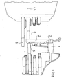
- the invention refers to a new and original machinery that, thanks to an axial robot arm and to an intelligent rod system, is able to cut off from the dies in getting out to the melting the different products in working of any shape and dimension and then to automatically separate the same in suitable containers or between the discharging material.
- the invented machinery consists of a axial robot arm 1, able of programmed movements X, Y and rotatory, that puts the die 2 in working in the more adequate position for the separation of each determined part 3 that must be separated.
- Said die 2 is placed in median position between two containment bodies 4A and 4B.
- Said containment bodies are placed frontally and back to the die 2 and they have holes 5 to permit the crossing of the rods 6.
- Said holes 5 and the corresponding rods 6 are placed with regular spaces according lines and columns.
- the rods 6 have a motion of translation to be programmed by a touch screen and to be driven to a translation unit 7.
- Said translation unit 7, in the main version, consists of a timing belt 8 connected to the rod 6 by flask 9.
- the timing belt 8 is kept parallel to the rod 6 by means of pulleys 10A and 10B.
- Others pulleys 11 connect the timing belt 8 with a reduction gear 12 and an electric brushless engine 13.
- the motion to the timing belt 8 is given to the gears of the reduction gear, whereas the rotation in one way or in the other is given to the electric brushless engine 13.
- Said engine is then connected to a logic card 14 for the driving of the control of the way and of the velocity of the rotations of the electric engine 13 and consequently of the translations of the rod 6.
- Said logic card has also an electronic storage 15 for the control of the translations and of the translation times of the rods.
- the logic card 14 is then connected with a touch screen by means of what the operator can program, store and drive the translation of the rods in relation to the shape of each part to cut off. This is actuated by connection of the rods with a P.L.C. 16 or similar.
- the invented machinery provides the positioning of the die 2, by the robot arm 1, in median position between the containment bodies 4A and 4B.
- the electronic drive actuated to the logic card 14 and the P.L.C.
- the electric engines 13 are started, so to make going on the opposite rods 6 till the contact with the die 2.
- this phase are started to the containment bodies 4A and 4B only the rods 6 opposite to a side and to the other so to determine the temporary blocking of the die 2 near the material part 3 to cut off.
- the disposition of the opposite rods 6 in phase of temporary blocking is automatic and it is determined to the program set out before to the operator on the base of the position of the part 3 to cut off from the die 2.
- the translation motion of the rods 6 is driven to the electronic devices of the invented machinery.
- the choose of the rods 6 for the temporary fixing is necessary to avoid flexions of the die 2 in the subsequent phase of cutting of the part 3 to be cut off and consequent damages to the same die.
- the selection of the rods 6 in correspondence of the part 3 to cut off, the translation and the velocity of advancement of the same rods is decided to the operator by means the electronic components and they are stored for each type of die 2 so to can be recalled in the applications that have working of equal die 2.
- the number of rods 6 can change from a minimum of four rods (two opposite rods for the blocking and two rods for the folding and the cutting off) to a variable number of rods on the base of the number of parts 3 to cut off.
- the number of rods 6 is always in excess in comparison to which in use in a determined time, such as it is provided the starting of some of them on the base of the use necessity and their number must be able to adapt to the different types of dies 2 from which the cutting off of the parts 3 is provided.
- the cut off parts fall down into hoppers and from these onto belt conveyors and then in underlying containers different for the different types of products so permitting a quick storing and the recovery of the working rejections.
- the die 2, from which parts 3 are being cut off is freed to the temporary blocking rods 6 to be separately recovered.
- the translation of the rods is actuated providing in the translation device 7 double effect cylinders 17 connected with flask 9 to the rods so to have the translation of said rods 6.
- the advancement of the rods is driven also in this embodiment to conventional electronic devices connected to a P.L.C. 16 and controlled to the operator by the touch screen.
- Other embodiment provides the use of solenoids 18 placed onto the rods with way of the current variable on the base of the wanted translation direction of the rods 6 by means of device 19 to invert the motion of the current and return spring 20 to the initial position.
- the other sheets i.e. the sheets 4, 5, 6, 7and 8, show the function of the different phases of the invented machinery.
- the sheet 4 - figure 4 shows the positioning, actuated by means of the robot arm 1, of the die 2 in medium position between the containment bodies 4A and 4B of the rods 6.
- sheet 5 - figure 5 shows, always in prospective view, the temporary blocking phase.
- the sheet 6 - figure 6 is view of the percussion phase by means of the rod 6 onto the part 3 to be cut off from the die 2. In this phase is created the break line or also already the cutting of the part 3.
- the sheet 7 - figure 7 is view of the second phase of percussion of the part 3 with the rod 6 opposite to the previous one in using phase, while the rod 6 of the first percussion is in rest position.
- sheet 8 - figure 8 shows the advancement of the rod 6 over the die 2 with the part 3 already cuts off.
Landscapes
- Engineering & Computer Science (AREA)
- Mechanical Engineering (AREA)
- Perforating, Stamping-Out Or Severing By Means Other Than Cutting (AREA)
- Moulds For Moulding Plastics Or The Like (AREA)
- Specific Conveyance Elements (AREA)
- Mounting, Exchange, And Manufacturing Of Dies (AREA)
Abstract
Description
- It is known that in the melting, in the pressure casting or in any pieces obtained for die forming are present parts of material to be cut off to the dies in getting out to the pressure casting to permit the subsequent storing up of the working products and the recovery of the rejections. These material parts are at present cut off by hand and, always manually, they are stored. In a lot of known workings machineries are used that exploit the centrifugal force. With these machineries the separation of the suitable parts to the discharging ones is not obtained and this separation must be manually made. Then, they have the drawbacks to often determine faulty products. The invention refers to a new and original machinery that, thanks to an axial robot arm and to an intelligent rod system, is able to cut off from the dies in getting out to the melting the different products in working of any shape and dimension and then to automatically separate the same in suitable containers or between the discharging material. The invented machinery consists of a
axial robot arm 1, able of programmed movements X, Y and rotatory, that puts thedie 2 in working in the more adequate position for the separation of eachdetermined part 3 that must be separated. Said die 2 is placed in median position between twocontainment bodies 4A and 4B. Said containment bodies are placed frontally and back to thedie 2 and they haveholes 5 to permit the crossing of therods 6. Saidholes 5 and thecorresponding rods 6 are placed with regular spaces according lines and columns. Therods 6 have a motion of translation to be programmed by a touch screen and to be driven to atranslation unit 7. Saidtranslation unit 7, in the main version, consists of atiming belt 8 connected to therod 6 byflask 9. Thetiming belt 8 is kept parallel to therod 6 by means of pulleys 10A and 10B.Others pulleys 11 connect thetiming belt 8 with areduction gear 12 and an electricbrushless engine 13. The motion to thetiming belt 8 is given to the gears of the reduction gear, whereas the rotation in one way or in the other is given to the electricbrushless engine 13. Said engine is then connected to alogic card 14 for the driving of the control of the way and of the velocity of the rotations of theelectric engine 13 and consequently of the translations of therod 6. Said logic card has also anelectronic storage 15 for the control of the translations and of the translation times of the rods. Thelogic card 14 is then connected with a touch screen by means of what the operator can program, store and drive the translation of the rods in relation to the shape of each part to cut off. This is actuated by connection of the rods with a P.L.C. 16 or similar. In working phase the invented machinery provides the positioning of thedie 2, by therobot arm 1, in median position between thecontainment bodies logic card 14 and the P.L.C. 16, theelectric engines 13 are started, so to make going on theopposite rods 6 till the contact with thedie 2. In this phase are started to thecontainment bodies rods 6 opposite to a side and to the other so to determine the temporary blocking of thedie 2 near thematerial part 3 to cut off. The disposition of theopposite rods 6 in phase of temporary blocking is automatic and it is determined to the program set out before to the operator on the base of the position of thepart 3 to cut off from thedie 2. The translation motion of therods 6 is driven to the electronic devices of the invented machinery. The choose of therods 6 for the temporary fixing is necessary to avoid flexions of thedie 2 in the subsequent phase of cutting of thepart 3 to be cut off and consequent damages to the same die. For each single piece is stored into theelectronic storage 15 whichrods 6 must be used and the motion of advancement of the rods in blocking phase. So there is the blocking of thedie 2 by therods 6 in front and back to the piece. In the subsequent phase the operator determines which rods 6 to make going on in correspondence of thepart 3 to cut off. These opposite rods are to be advanced firstly translating to acontainment body 4A over the first part of the die 2. Subsequent, returned in initial position therod 6 of thecontainment body 4A, therods 6 opposite to the previous ones are advanced by means of thecontainment body 4B till over thedie 2. So a first phase of folding of the cutting offpart 3 is obtained, often already sufficient to determine the cutting from the die of saidparts 3. Then, there is a second phase able to obtain the final cutting of thepart 3, thanks to the advancement first in one way and then in the other of therods 6 that go to hit the parts to be cut off. The selection of therods 6 in correspondence of thepart 3 to cut off, the translation and the velocity of advancement of the same rods is decided to the operator by means the electronic components and they are stored for each type ofdie 2 so to can be recalled in the applications that have working ofequal die 2. The number ofrods 6 can change from a minimum of four rods (two opposite rods for the blocking and two rods for the folding and the cutting off) to a variable number of rods on the base of the number ofparts 3 to cut off. However, the number ofrods 6 is always in excess in comparison to which in use in a determined time, such as it is provided the starting of some of them on the base of the use necessity and their number must be able to adapt to the different types ofdies 2 from which the cutting off of theparts 3 is provided. The cut off parts fall down into hoppers and from these onto belt conveyors and then in underlying containers different for the different types of products so permitting a quick storing and the recovery of the working rejections. At the end, thedie 2, from whichparts 3 are being cut off, is freed to thetemporary blocking rods 6 to be separately recovered. In other embodiment the translation of the rods is actuated providing in thetranslation device 7double effect cylinders 17 connected withflask 9 to the rods so to have the translation of saidrods 6. The advancement of the rods is driven also in this embodiment to conventional electronic devices connected to a P.L.C. 16 and controlled to the operator by the touch screen. Other embodiment provides the use ofsolenoids 18 placed onto the rods with way of the current variable on the base of the wanted translation direction of therods 6 by means ofdevice 19 to invert the motion of the current and returnspring 20 to the initial position. Conventional electronic devices, the disposition and the installation of which are known for an operator of the field, are placed for the driving of the translation motion of therods 6 so as it is known in the previous art the use of driving and storage electronic cards and are known the necessary connections for the right working of the invented machinery. The invented machinery is illustrated in a merely and not limiting way in the drawings ofsheets sheet 1 figure 1 is a perspective view of thedevice 7 for the translation of the rods in the main embodiment. Insheet 2 figure 2 is view of the other embodiment of thedevice 7 in which the advancement motion of therods 6 is realized bydouble effect cylinders 19. Insheet 3 figure 3 is view of further embodiment where the motion of therods 6 is due to the action ofsolenoids 18. The other sheets, i.e. thesheets 7and 8, show the function of the different phases of the invented machinery. In particular in the sheet 4 - figure 4 shows the positioning, actuated by means of therobot arm 1, of thedie 2 in medium position between thecontainment bodies rods 6. In sheet 5 - figure 5 shows, always in prospective view, the temporary blocking phase. The sheet 6 - figure 6 is view of the percussion phase by means of therod 6 onto thepart 3 to be cut off from thedie 2. In this phase is created the break line or also already the cutting of thepart 3. The sheet 7 - figure 7 is view of the second phase of percussion of thepart 3 with therod 6 opposite to the previous one in using phase, while therod 6 of the first percussion is in rest position. In sheet 8 - figure 8 shows the advancement of therod 6 over thedie 2 with thepart 3 already cuts off.
Claims (10)
- Machinery for cutting off and storing parts from pressure casting dies or similar characterized in that to consist of an axial robot arm (1), able of programmed movements X, Y and rotatory and able to put a die (2) in median position between two containment bodies (4A, 4B), and of rods (6) placed with regular spaces according lines and columns and connected to a translation unit (7) able to actuate a translation motion to the rods (6) and to be programmed by a touch screen.
- Machinery for cutting off and storing parts from pressure casting dies or similar, as for the previous claim, characterized in that the translation unit (7) consists of a timing belt (8) connected to the rod (6) by a flask (9) and kept parallel to the rod (6) by means of pulleys (10A, 10B).
- Machinery for cutting off and storing parts from pressure casting dies or similar, as for the claims 1 and 2, characterized in that the timing belt (8) is connected with pulleys (11), with a reduction gear (12) and with an electric brushless engine (13).
- Machinery for cutting off and storing parts from pressure casting dies or similar, as for claims 1-3, characterized in that the electric engine (13) is connected to logic card (14) for the driving of the control of the way and of the velocity of the rotations of the electric engine (13) and consequently of the translations of the rods (6).
- Machinery for cutting off and storing parts from pressure casting dies or similar, as for claims 1-4, characterized in that the logic card (14) has an electronic storage (15) for the control of the translations and of the translation times of the rods (6) and it has a connection to a P.L.C. (16) so to have on a touch screen the possibility for the operator to program, store and drive the translation of the rods (6) in relation to the shape of each part (3) to cut off from the die (2).
- Machinery for cutting off and storing parts from pressure casting dies or similar, as for claim 1, characterized in that the device (7) for the translation of the rods (6) consists of double effect cylinders (17) with advancement of the rods driven to P.L.C. (16).
- Machinery for cutting off and storing parts from pressure casting dies or similar, as for claim 1, characterized in that the device (7) for the translation of the rods (6) provides the use of solenoids (18) placed onto the rods with way of the current variable on the base of the wanted translation direction of the rod and by means of a device (19) to invert the motion of the current and return spring (20) to recall the initial position.
- Machinery for cutting off and storing parts from pressure casting dies or similar, as for claim 1, characterized in that the device (7) of translation of the rods is obtained with gears connected to the rod (6) and with the electric engine (13) and it is driven by a P.L.C. (16).
- Machinery for cutting off and storing parts from pressure casting dies or similar, as for the previous claims, characterized in that the number of rods (6) can change on the base of the parts (3) to cut off.
- Machinery for cutting off and storing parts from pressure casting dies or similar, as for the previous claims, characterized in that the parts (3) cut off to the die (2) fall down into hoppers and from these onto belt conveyors and then in underlying containers different for the different types of products so permitting a quick storing and the recovery of the working rejections.
Priority Applications (4)
| Application Number | Priority Date | Filing Date | Title |
|---|---|---|---|
| EP06425198A EP1837101B1 (en) | 2006-03-22 | 2006-03-22 | Machinery for cutting off and storing parts from pressure casting articles or similar |
| AT06425198T ATE454232T1 (en) | 2006-03-22 | 2006-03-22 | DEVICE FOR SEPARATING AND STORING PARTS OF A DIE-CAST PRODUCT OR SIMILAR |
| DE602006011573T DE602006011573D1 (en) | 2006-03-22 | 2006-03-22 | Apparatus for separating and storing parts of die-cast product or the like |
| PCT/IB2007/000712 WO2007122462A2 (en) | 2006-03-22 | 2007-03-21 | Machinery for cutting off and storing parts from pressure casting dies or similar |
Applications Claiming Priority (1)
| Application Number | Priority Date | Filing Date | Title |
|---|---|---|---|
| EP06425198A EP1837101B1 (en) | 2006-03-22 | 2006-03-22 | Machinery for cutting off and storing parts from pressure casting articles or similar |
Publications (2)
| Publication Number | Publication Date |
|---|---|
| EP1837101A1 true EP1837101A1 (en) | 2007-09-26 |
| EP1837101B1 EP1837101B1 (en) | 2010-01-06 |
Family
ID=36930670
Family Applications (1)
| Application Number | Title | Priority Date | Filing Date |
|---|---|---|---|
| EP06425198A Expired - Lifetime EP1837101B1 (en) | 2006-03-22 | 2006-03-22 | Machinery for cutting off and storing parts from pressure casting articles or similar |
Country Status (4)
| Country | Link |
|---|---|
| EP (1) | EP1837101B1 (en) |
| AT (1) | ATE454232T1 (en) |
| DE (1) | DE602006011573D1 (en) |
| WO (1) | WO2007122462A2 (en) |
Cited By (2)
| Publication number | Priority date | Publication date | Assignee | Title |
|---|---|---|---|---|
| CN104114304A (en) * | 2011-12-12 | 2014-10-22 | Tecnalia研究与创新基金 | Method and system for separating cast parts from a population obtained by means of a casting process |
| CN105855505A (en) * | 2016-06-03 | 2016-08-17 | 宁波职业技术学院 | Automatic system for die-casting product nozzle punching and technological process thereof |
Families Citing this family (1)
| Publication number | Priority date | Publication date | Assignee | Title |
|---|---|---|---|---|
| CN103949605B (en) * | 2014-04-14 | 2016-04-20 | 临海市中创自动化设备有限公司 | Automatically deduction is pulled |
Citations (1)
| Publication number | Priority date | Publication date | Assignee | Title |
|---|---|---|---|---|
| US5597521A (en) * | 1995-06-09 | 1997-01-28 | Wickham; John L. | Unloader-separator |
-
2006
- 2006-03-22 AT AT06425198T patent/ATE454232T1/en not_active IP Right Cessation
- 2006-03-22 DE DE602006011573T patent/DE602006011573D1/en not_active Expired - Lifetime
- 2006-03-22 EP EP06425198A patent/EP1837101B1/en not_active Expired - Lifetime
-
2007
- 2007-03-21 WO PCT/IB2007/000712 patent/WO2007122462A2/en not_active Ceased
Patent Citations (1)
| Publication number | Priority date | Publication date | Assignee | Title |
|---|---|---|---|---|
| US5597521A (en) * | 1995-06-09 | 1997-01-28 | Wickham; John L. | Unloader-separator |
Cited By (4)
| Publication number | Priority date | Publication date | Assignee | Title |
|---|---|---|---|---|
| CN104114304A (en) * | 2011-12-12 | 2014-10-22 | Tecnalia研究与创新基金 | Method and system for separating cast parts from a population obtained by means of a casting process |
| CN104114304B (en) * | 2011-12-12 | 2016-01-06 | Tecnalia研究与创新基金 | Method and system for separating cast parts from a population obtained by means of a casting process |
| CN105855505A (en) * | 2016-06-03 | 2016-08-17 | 宁波职业技术学院 | Automatic system for die-casting product nozzle punching and technological process thereof |
| CN105855505B (en) * | 2016-06-03 | 2019-03-08 | 宁波职业技术学院 | A die-casting product nozzle blanking automation system and its technological process |
Also Published As
| Publication number | Publication date |
|---|---|
| WO2007122462A2 (en) | 2007-11-01 |
| DE602006011573D1 (en) | 2010-02-25 |
| WO2007122462A3 (en) | 2008-01-10 |
| ATE454232T1 (en) | 2010-01-15 |
| EP1837101B1 (en) | 2010-01-06 |
Similar Documents
| Publication | Publication Date | Title |
|---|---|---|
| FI65049B (en) | ANORDNING FOER ATT AOSTADKOMMA SAMVERKAN MELLAN ROERELSER HOS I EN MASKIN ELLER ANLAEGGNING INGAOENDE ARBETSDON | |
| US6983877B2 (en) | Automatic hole punch | |
| SE455057B (en) | PROCEDURE AND DEVICE FOR CUTTING AND GRADING OF RODS | |
| BE1011547A3 (en) | APPARATUS FOR SUPPLYING FIBERS TO A FILLING MACHINE AT A BRUSH MANUFACTURING MACHINE. | |
| EP1837101A1 (en) | Machinery for cutting off and storing parts from pressure casting articles or similar | |
| DE2352864B1 (en) | Control device for blowing and suction air on printing machines | |
| BE1008378A3 (en) | Method and device for supplying fibers to a filling tool AT A brush manufacturing MACHINE. | |
| CN109910036B (en) | Manipulator and material grabbing equipment | |
| EP3606831B1 (en) | Pick and place station | |
| CN209226067U (en) | The level locating mechanism of profile | |
| EP2385015A1 (en) | Screw stopper removing machine for bottles contained in cases | |
| SE533503C2 (en) | vibratory feeder | |
| EP1375059A3 (en) | Device for storing and dispensing tools for machines | |
| RU2004125541A (en) | FEEDING DEVICE OF PROTECTED MATERIAL AND METHOD OF SUBMISSION OF PROTECTED MATERIAL | |
| CN109275923A (en) | A kind of full-automatic spherical nut cracker shuttle back and forth | |
| US2718018A (en) | Machine for pressing and building-in books | |
| CN114160698A (en) | Servo control tank manufacturing equipment | |
| KR20230119841A (en) | Daikon Cutting device for kkakdugi | |
| US875746A (en) | Machine for making radiators. | |
| CN208067499U (en) | A kind of automatic charging gear-hobbing machine | |
| EP1577271B1 (en) | Transfer mechanism for glass articles from a station of an IS machine to a conveyor | |
| US3257002A (en) | Apparatus for setting up and placement of partitions for containers | |
| US336304A (en) | ellis | |
| CN213415447U (en) | Hydraulic double-head type automatic material rack | |
| CN207497595U (en) | The handle conveying device of packaging bag |
Legal Events
| Date | Code | Title | Description |
|---|---|---|---|
| PUAI | Public reference made under article 153(3) epc to a published international application that has entered the european phase |
Free format text: ORIGINAL CODE: 0009012 |
|
| AK | Designated contracting states |
Kind code of ref document: A1 Designated state(s): AT BE BG CH CY CZ DE DK EE ES FI FR GB GR HU IE IS IT LI LT LU LV MC NL PL PT RO SE SI SK TR |
|
| AX | Request for extension of the european patent |
Extension state: AL BA HR MK YU |
|
| AKX | Designation fees paid | ||
| REG | Reference to a national code |
Ref country code: DE Ref legal event code: 8566 |
|
| 17P | Request for examination filed |
Effective date: 20080731 |
|
| RBV | Designated contracting states (corrected) |
Designated state(s): AT BE BG CH CY CZ DE DK EE ES FI FR GB GR HU IE IS IT LI LT LU LV MC NL PL PT RO SE SI SK TR |
|
| GRAP | Despatch of communication of intention to grant a patent |
Free format text: ORIGINAL CODE: EPIDOSNIGR1 |
|
| GRAS | Grant fee paid |
Free format text: ORIGINAL CODE: EPIDOSNIGR3 |
|
| GRAA | (expected) grant |
Free format text: ORIGINAL CODE: 0009210 |
|
| AK | Designated contracting states |
Kind code of ref document: B1 Designated state(s): AT BE BG CH CY CZ DE DK EE ES FI FR GB GR HU IE IS IT LI LT LU LV MC NL PL PT RO SE SI SK TR |
|
| REG | Reference to a national code |
Ref country code: GB Ref legal event code: FG4D |
|
| REG | Reference to a national code |
Ref country code: CH Ref legal event code: EP |
|
| REG | Reference to a national code |
Ref country code: IE Ref legal event code: FG4D |
|
| REF | Corresponds to: |
Ref document number: 602006011573 Country of ref document: DE Date of ref document: 20100225 Kind code of ref document: P |
|
| REG | Reference to a national code |
Ref country code: NL Ref legal event code: VDEP Effective date: 20100106 |
|
| PG25 | Lapsed in a contracting state [announced via postgrant information from national office to epo] |
Ref country code: SI Free format text: LAPSE BECAUSE OF FAILURE TO SUBMIT A TRANSLATION OF THE DESCRIPTION OR TO PAY THE FEE WITHIN THE PRESCRIBED TIME-LIMIT Effective date: 20100106 |
|
| LTIE | Lt: invalidation of european patent or patent extension |
Effective date: 20100106 |
|
| PG25 | Lapsed in a contracting state [announced via postgrant information from national office to epo] |
Ref country code: AT Free format text: LAPSE BECAUSE OF FAILURE TO SUBMIT A TRANSLATION OF THE DESCRIPTION OR TO PAY THE FEE WITHIN THE PRESCRIBED TIME-LIMIT Effective date: 20100106 |
|
| PG25 | Lapsed in a contracting state [announced via postgrant information from national office to epo] |
Ref country code: LT Free format text: LAPSE BECAUSE OF FAILURE TO SUBMIT A TRANSLATION OF THE DESCRIPTION OR TO PAY THE FEE WITHIN THE PRESCRIBED TIME-LIMIT Effective date: 20100106 Ref country code: ES Free format text: LAPSE BECAUSE OF FAILURE TO SUBMIT A TRANSLATION OF THE DESCRIPTION OR TO PAY THE FEE WITHIN THE PRESCRIBED TIME-LIMIT Effective date: 20100417 Ref country code: NL Free format text: LAPSE BECAUSE OF FAILURE TO SUBMIT A TRANSLATION OF THE DESCRIPTION OR TO PAY THE FEE WITHIN THE PRESCRIBED TIME-LIMIT Effective date: 20100106 Ref country code: PT Free format text: LAPSE BECAUSE OF FAILURE TO SUBMIT A TRANSLATION OF THE DESCRIPTION OR TO PAY THE FEE WITHIN THE PRESCRIBED TIME-LIMIT Effective date: 20100506 Ref country code: IS Free format text: LAPSE BECAUSE OF FAILURE TO SUBMIT A TRANSLATION OF THE DESCRIPTION OR TO PAY THE FEE WITHIN THE PRESCRIBED TIME-LIMIT Effective date: 20100506 |
|
| PG25 | Lapsed in a contracting state [announced via postgrant information from national office to epo] |
Ref country code: PL Free format text: LAPSE BECAUSE OF FAILURE TO SUBMIT A TRANSLATION OF THE DESCRIPTION OR TO PAY THE FEE WITHIN THE PRESCRIBED TIME-LIMIT Effective date: 20100106 Ref country code: LV Free format text: LAPSE BECAUSE OF FAILURE TO SUBMIT A TRANSLATION OF THE DESCRIPTION OR TO PAY THE FEE WITHIN THE PRESCRIBED TIME-LIMIT Effective date: 20100106 Ref country code: FI Free format text: LAPSE BECAUSE OF FAILURE TO SUBMIT A TRANSLATION OF THE DESCRIPTION OR TO PAY THE FEE WITHIN THE PRESCRIBED TIME-LIMIT Effective date: 20100106 |
|
| PGFP | Annual fee paid to national office [announced via postgrant information from national office to epo] |
Ref country code: DE Payment date: 20100406 Year of fee payment: 5 |
|
| PG25 | Lapsed in a contracting state [announced via postgrant information from national office to epo] |
Ref country code: BE Free format text: LAPSE BECAUSE OF FAILURE TO SUBMIT A TRANSLATION OF THE DESCRIPTION OR TO PAY THE FEE WITHIN THE PRESCRIBED TIME-LIMIT Effective date: 20100106 Ref country code: SE Free format text: LAPSE BECAUSE OF FAILURE TO SUBMIT A TRANSLATION OF THE DESCRIPTION OR TO PAY THE FEE WITHIN THE PRESCRIBED TIME-LIMIT Effective date: 20100106 Ref country code: RO Free format text: LAPSE BECAUSE OF FAILURE TO SUBMIT A TRANSLATION OF THE DESCRIPTION OR TO PAY THE FEE WITHIN THE PRESCRIBED TIME-LIMIT Effective date: 20100106 Ref country code: MC Free format text: LAPSE BECAUSE OF NON-PAYMENT OF DUE FEES Effective date: 20100331 Ref country code: GR Free format text: LAPSE BECAUSE OF FAILURE TO SUBMIT A TRANSLATION OF THE DESCRIPTION OR TO PAY THE FEE WITHIN THE PRESCRIBED TIME-LIMIT Effective date: 20100407 Ref country code: EE Free format text: LAPSE BECAUSE OF FAILURE TO SUBMIT A TRANSLATION OF THE DESCRIPTION OR TO PAY THE FEE WITHIN THE PRESCRIBED TIME-LIMIT Effective date: 20100106 Ref country code: CY Free format text: LAPSE BECAUSE OF FAILURE TO SUBMIT A TRANSLATION OF THE DESCRIPTION OR TO PAY THE FEE WITHIN THE PRESCRIBED TIME-LIMIT Effective date: 20100106 |
|
| REG | Reference to a national code |
Ref country code: CH Ref legal event code: PL |
|
| PLBE | No opposition filed within time limit |
Free format text: ORIGINAL CODE: 0009261 |
|
| STAA | Information on the status of an ep patent application or granted ep patent |
Free format text: STATUS: NO OPPOSITION FILED WITHIN TIME LIMIT |
|
| PG25 | Lapsed in a contracting state [announced via postgrant information from national office to epo] |
Ref country code: SK Free format text: LAPSE BECAUSE OF FAILURE TO SUBMIT A TRANSLATION OF THE DESCRIPTION OR TO PAY THE FEE WITHIN THE PRESCRIBED TIME-LIMIT Effective date: 20100106 Ref country code: CZ Free format text: LAPSE BECAUSE OF FAILURE TO SUBMIT A TRANSLATION OF THE DESCRIPTION OR TO PAY THE FEE WITHIN THE PRESCRIBED TIME-LIMIT Effective date: 20100106 Ref country code: BG Free format text: LAPSE BECAUSE OF FAILURE TO SUBMIT A TRANSLATION OF THE DESCRIPTION OR TO PAY THE FEE WITHIN THE PRESCRIBED TIME-LIMIT Effective date: 20100406 |
|
| PGFP | Annual fee paid to national office [announced via postgrant information from national office to epo] |
Ref country code: GB Payment date: 20100423 Year of fee payment: 5 |
|
| 26N | No opposition filed |
Effective date: 20101007 |
|
| REG | Reference to a national code |
Ref country code: FR Ref legal event code: ST Effective date: 20101130 |
|
| PG25 | Lapsed in a contracting state [announced via postgrant information from national office to epo] |
Ref country code: DK Free format text: LAPSE BECAUSE OF FAILURE TO SUBMIT A TRANSLATION OF THE DESCRIPTION OR TO PAY THE FEE WITHIN THE PRESCRIBED TIME-LIMIT Effective date: 20100106 Ref country code: FR Free format text: LAPSE BECAUSE OF NON-PAYMENT OF DUE FEES Effective date: 20100331 Ref country code: IE Free format text: LAPSE BECAUSE OF NON-PAYMENT OF DUE FEES Effective date: 20100322 |
|
| PG25 | Lapsed in a contracting state [announced via postgrant information from national office to epo] |
Ref country code: LI Free format text: LAPSE BECAUSE OF NON-PAYMENT OF DUE FEES Effective date: 20100331 Ref country code: CH Free format text: LAPSE BECAUSE OF NON-PAYMENT OF DUE FEES Effective date: 20100331 |
|
| GBPC | Gb: european patent ceased through non-payment of renewal fee |
Effective date: 20110322 |
|
| PG25 | Lapsed in a contracting state [announced via postgrant information from national office to epo] |
Ref country code: DE Free format text: LAPSE BECAUSE OF NON-PAYMENT OF DUE FEES Effective date: 20111001 |
|
| REG | Reference to a national code |
Ref country code: DE Ref legal event code: R119 Ref document number: 602006011573 Country of ref document: DE Effective date: 20111001 |
|
| PG25 | Lapsed in a contracting state [announced via postgrant information from national office to epo] |
Ref country code: GB Free format text: LAPSE BECAUSE OF NON-PAYMENT OF DUE FEES Effective date: 20110322 |
|
| PG25 | Lapsed in a contracting state [announced via postgrant information from national office to epo] |
Ref country code: LU Free format text: LAPSE BECAUSE OF NON-PAYMENT OF DUE FEES Effective date: 20100322 Ref country code: HU Free format text: LAPSE BECAUSE OF FAILURE TO SUBMIT A TRANSLATION OF THE DESCRIPTION OR TO PAY THE FEE WITHIN THE PRESCRIBED TIME-LIMIT Effective date: 20100707 |
|
| PGFP | Annual fee paid to national office [announced via postgrant information from national office to epo] |
Ref country code: IT Payment date: 20120329 Year of fee payment: 7 |
|
| PG25 | Lapsed in a contracting state [announced via postgrant information from national office to epo] |
Ref country code: TR Free format text: LAPSE BECAUSE OF FAILURE TO SUBMIT A TRANSLATION OF THE DESCRIPTION OR TO PAY THE FEE WITHIN THE PRESCRIBED TIME-LIMIT Effective date: 20100106 |
|
| PG25 | Lapsed in a contracting state [announced via postgrant information from national office to epo] |
Ref country code: IT Free format text: LAPSE BECAUSE OF NON-PAYMENT OF DUE FEES Effective date: 20130322 |