EP1837215A1 - Fahrzeugklimaanlage - Google Patents
Fahrzeugklimaanlage Download PDFInfo
- Publication number
- EP1837215A1 EP1837215A1 EP07005619A EP07005619A EP1837215A1 EP 1837215 A1 EP1837215 A1 EP 1837215A1 EP 07005619 A EP07005619 A EP 07005619A EP 07005619 A EP07005619 A EP 07005619A EP 1837215 A1 EP1837215 A1 EP 1837215A1
- Authority
- EP
- European Patent Office
- Prior art keywords
- temperature
- refrigerant
- radiator
- vehicle speed
- control
- Prior art date
- Legal status (The legal status is an assumption and is not a legal conclusion. Google has not performed a legal analysis and makes no representation as to the accuracy of the status listed.)
- Granted
Links
Images
Classifications
-
- B—PERFORMING OPERATIONS; TRANSPORTING
- B60—VEHICLES IN GENERAL
- B60H—ARRANGEMENTS OF HEATING, COOLING, VENTILATING OR OTHER AIR-TREATING DEVICES SPECIALLY ADAPTED FOR PASSENGER OR GOODS SPACES OF VEHICLES
- B60H1/00—Heating, cooling or ventilating devices
- B60H1/00642—Control systems or circuits; Control members or indication devices for heating, cooling or ventilating devices
- B60H1/00735—Control systems or circuits characterised by their input, i.e. by the detection, measurement or calculation of particular conditions, e.g. signal treatment, dynamic models
- B60H1/00764—Control systems or circuits characterised by their input, i.e. by the detection, measurement or calculation of particular conditions, e.g. signal treatment, dynamic models the input being a vehicle driving condition, e.g. speed
-
- B—PERFORMING OPERATIONS; TRANSPORTING
- B60—VEHICLES IN GENERAL
- B60H—ARRANGEMENTS OF HEATING, COOLING, VENTILATING OR OTHER AIR-TREATING DEVICES SPECIALLY ADAPTED FOR PASSENGER OR GOODS SPACES OF VEHICLES
- B60H1/00—Heating, cooling or ventilating devices
- B60H1/00642—Control systems or circuits; Control members or indication devices for heating, cooling or ventilating devices
- B60H1/00814—Control systems or circuits characterised by their output, for controlling particular components of the heating, cooling or ventilating installation
- B60H1/00878—Control systems or circuits characterised by their output, for controlling particular components of the heating, cooling or ventilating installation the components being temperature regulating devices
- B60H1/00885—Controlling the flow of heating or cooling liquid, e.g. valves or pumps
-
- B—PERFORMING OPERATIONS; TRANSPORTING
- B60—VEHICLES IN GENERAL
- B60H—ARRANGEMENTS OF HEATING, COOLING, VENTILATING OR OTHER AIR-TREATING DEVICES SPECIALLY ADAPTED FOR PASSENGER OR GOODS SPACES OF VEHICLES
- B60H1/00—Heating, cooling or ventilating devices
- B60H1/32—Cooling devices
- B60H1/3204—Cooling devices using compression
- B60H1/3205—Control means therefor
- B60H1/3208—Vehicle drive related control of the compressor drive means, e.g. for fuel saving purposes
-
- B—PERFORMING OPERATIONS; TRANSPORTING
- B60—VEHICLES IN GENERAL
- B60H—ARRANGEMENTS OF HEATING, COOLING, VENTILATING OR OTHER AIR-TREATING DEVICES SPECIALLY ADAPTED FOR PASSENGER OR GOODS SPACES OF VEHICLES
- B60H1/00—Heating, cooling or ventilating devices
- B60H1/32—Cooling devices
- B60H2001/3236—Cooling devices information from a variable is obtained
- B60H2001/3255—Cooling devices information from a variable is obtained related to temperature
- B60H2001/326—Cooling devices information from a variable is obtained related to temperature of the refrigerant at a condensing unit
-
- B—PERFORMING OPERATIONS; TRANSPORTING
- B60—VEHICLES IN GENERAL
- B60H—ARRANGEMENTS OF HEATING, COOLING, VENTILATING OR OTHER AIR-TREATING DEVICES SPECIALLY ADAPTED FOR PASSENGER OR GOODS SPACES OF VEHICLES
- B60H1/00—Heating, cooling or ventilating devices
- B60H1/32—Cooling devices
- B60H2001/3269—Cooling devices output of a control signal
- B60H2001/3285—Cooling devices output of a control signal related to an expansion unit
Definitions
- the present invention relates to a vehicular air conditioner, and, more particularly to an operation control of a refrigeration cycle device using CO2 refrigerant.
- CO2 carbon dioxide
- the critical temperature of the CO2 refrigerant is extremely low. Therefore, when the outside air temperature is high, the refrigerant temperature in the radiator (gas cooler) becomes higher than the critical temperature, and CO2 is not condensed at an outlet of the radiator.
- the refrigerant temperature at the outlet of the radiator is determined by the radiation ability of the radiator and the outside air temperature, but since the outside air temperature can not be controlled, the refrigerant pressure at the outlet side of the compressor is usually controlled. For example, when the outside air temperature is high, in order to secure sufficient cooling ability, an opening of an expansion valve provided on the side of the outlet of the radiator is reduced, thereby increasing the refrigerant pressure.
- the refrigerant pressure can be increased by reducing the opening of the expansion valve, but if the refrigerant pressure becomes higher, the refrigerant temperature at the outlet of the compressor is also increased.
- the refrigerant temperature at the radiator outlet is suppressed to a predetermined level by sufficient cooling wind during running of a vehicle, but when the vehicle is idling while waiting at a traffic signal or at the time of a traffic hold-up, or when there is almost no cooling wind when the vehicle stops or runs at low speed, the refrigerant temperature is abruptly increased at the compressor outlet.
- the present invention provides a vehicular air conditioner comprising a compressor for compressing a refrigerant, a radiator for cooling the refrigerant compressed by the compressor by heat exchange with cooling wind, a temperature sensor for detecting a refrigerant temperature on the side of an outlet of the radiator, a decompressor for decompressing the refrigerant which passes through the radiator in accordance with a designated decompression amount, an evaporator for evaporating the refrigerant which passes through the decompressor by heat exchange with conditioned wind, a gas/liquid separator for separating the refrigerant discharged from the evaporator into gas and liquid, a vehicle speed detector for detecting a vehicle speed, and a control unit for designating the decompression amount for the decompressor, wherein the control unit calculates a target refrigerant pressure using the refrigerant temperature detected by the temperature sensor, a vehicle speed detected by the vehicle speed detector and a control equation defined for calculating the target refrigerant pressure, and the control unit
- the control unit defines a difference between a temperature of outside air and a temperature of air which reversely flows through the radiator, as a maximum value of temperature to be used as a correction value.
- control unit includes, in the control equation defined for calculating the target refrigerant pressure, a temperature correction term obtained by dividing, by a vehicle speed detected by the vehicle speed detector, a correction value which is a difference between a temperature of outside air and a temperature of air which reversely flows through the radiator.
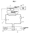
- Fig. 1 is a systemblock diagram of a vehicular air conditioner according to an embodiment of the present invention.
- the vehicular air conditioner of the embodiment includes a refrigeration cycle device 1 which circulates CO2 refrigerant to heat-exchange between the refrigerant and cooling wind.
- the refrigeration cycle device 1 includes a compressor 2, a radiator 3, an expansion valve (decompressor) 4, an evaporator' 5 and an accumulator (gas/liquid separator) 6. These compressor 2, radiator 3, expansion valve 4, evaporator 5 and accumulator 6 are connected to one another through pipes.
- the refrigeration cycle device 1 circulates, in this device, CO2 refrigerant provided with kinetic energy by the compressor 2.
- An air conditioning ECU (control unit) 7 for controlling a decompression amount of the expansion valve 4 is connected to the refrigeration cycle device 1.
- the compressor 2 is disposed outside of a passenger room such as an engine room.
- the compressor 2 compresses a low pressure gaseous refrigerant sucked from the accumulator 6, and discharges the same into the radiator 3 as a high temperature and high pressure gaseous refrigerant.
- the compressor 2 is configured to compress CO2 refrigerant by driving force of a motor (not shown).
- the radiator 3 cools high temperature and high pressure gaseous refrigerant discharged from the compressor 2.
- the radiator 3 is disposed outside of the passenger room. More specifically, the radiator 3 is disposed in front of the engine room so that cooling wind (runningwind) introduced as outside air impinges on the radiator 3.
- the radiator 3 heat-exchanges between the high temperature and high pressure gaseous refrigerant passing through the radiator 3 and the blowing cooling wind, thereby cooling the heat of the high temperature and high pressure gaseous refrigerant.
- a temperature sensor (temperature detector) 8 which detects the outlet refrigerant temperature is provided on the side of the outlet of the radiator 3. The outlet refrigerant temperature detected by the temperature sensor (temperature detector) 8 is sent to the air conditioning ECU 7.
- the expansion valve 4 decompresses (expands) the high temperature and high pressure gaseous refrigerant which is output from the radiator 3 and atomizes the same into a low temperature and low pressure nebulosus refrigerant.
- the expansion valve 4 decompresses the CO2 refrigerant and controls the outlet refrigerant pressure of the radiator 3.
- the decompressing amount of the expansion valve 4 of the present embodiment is controlled by an electric signal from the later-described air conditioning ECU 7.
- a pressure-reducing valve disclosed in Japanese Patent Application No. 2000-206780 can be used as the expansion valve 4.
- the evaporator 5 is disposed in an air conditioning duct 11.
- the evaporator 5 makes a low temperature and low pressure nebulosus refrigerant supplied from the radiator 3 through the expansion valve 4 absorb heat of conditioned air generated by an air conditioning fan 12.
- the refrigerant which is brought into the low temperature and low pressure nebulosus refrigerant by the expansion valve 4 passes through the evaporator 5.
- the refrigerant absorbs heat of the conditioned air flowing through the air conditioning duct 11 and vaporizes.
- the conditioned air whose heat is absorbed by the refrigerant in the evaporator 5 is dehumidified and becomes cooling wind, and is sent into the passenger room from a blowoff opening 13.
- the accumulator 6 decomposes a refrigerant discharged from the evaporator 5 into gas and liquid, and stores liquid refrigerant. Gaseous refrigerant separated from the liquid refrigerant is sent to the compressor 2.
- the air conditioning ECU 7 comprises a microcomputer including a CPU, a RAM, a ROM and an I/O interface.
- the outlet refrigerant temperature detected by the temperature sensor 8 and a vehicle speed (signal) detected by a vehicle speed sensor (vehicle speed detector) 10 connected to a transmission gear of an engine unit 9 are input to the air conditioning ECU 7.
- the air conditioning ECU 7 calculates a target refrigerant pressure using the outlet refrigerant temperature, the vehicle speed and a later-described control equation (2) defined for calculating the target refrigerant pressure.
- the air conditioning ECU 7 converts a decompression amount corresponding to the target refrigerant pressure into an electric signal (opening/closing duty signal), and sends the same to the expansion valve 4.
- the air conditioning ECU 7 can comprise a plurality of microcomputers.
- the air conditioning ECU 7 can perform a plurality of control functions in addition to the control of the decompression amount of the expansion valve 4.
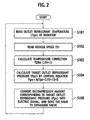
- the air conditioning ECU 7 reads an outlet refrigerant temperature Tgo of the radiator 3 detected by the temperature sensor 8 (step S101). Then, a vehicle speed V detected by the vehicle speed sensor 10 is read (step S102). Then, the air conditioning ECU 7 calculates a temperature correction term included in the control equation.
- the control equation defined for calculating the target refrigerant pressure will be explained.
- the temperature correction term is only the correction value C, and the calculated Pgo is suppressed to a low value by subtracting the correction value C from Tgo.
- the temperature of the refrigerant is not increased by the reversely flowing air, and the term (V+1) becomes greater than the correction value C. Therefore, the influence of the temperature correction term becomes substantially zero, and the calculation result of the control equation (2) is almost the same as that of the control equation (1) .
- the air conditioning ECU 7 calculates the temperature correction term from the vehicle speed V and the correction value C which are read in step S102 (step S103) .
- the air conditioning ECU 7 calculates the target refrigerant pressure Pgo by the control equation (2) using the constants A and B as well as the outlet refrigerant temperature Tgo read in the step S101 in the temperature correction term (step S104).
- the air conditioning ECU 7 obtains the decompression amount corresponding to the target refrigerant pressure Pgo such that the refrigerant pressure of the refrigeration cycle device 1 matches with the target refrigerant pressure Pgo, and converts the decompression amount into an electric signal (open/close duty signal), and sends the same to the expansion valve 4 (step S105).
- the temperature correction term is for the correction value C.
- the calculated target refrigerant pressure Pgo can be suppressed to a low level.
- the temperature of the refrigerant is not increased by the reverse flow of air through the radiator 3 and thus, the term (V+1) becomes greater with respect to the correction value C. Therefore, the influence of the temperature correction term substantially becomes zero, and the same calculation result as that of the control equation (1) is obtained. Since the target refrigerant pressure Pgo does not receive the influence of the temperature correction term, it is possible to set a suitable refrigerant pressure for the refrigeration cycle device 1.
- the vehicular air conditioner of the present embodiment it is possible to stably operate the refrigeration cycle device 1 when the vehicle is running and when the vehicle is idling.
- the maximum value of the correction value C is the difference between the outside air temperature and the temperature of the reversely flowing air through the radiator 3. Therefore, it is possible to cancel the influence of the temperature of the reversely flowing air which is different depending upon the vehicle (vehicle type), and to precisely control the temperature.
- the temperature correction term is obtained by dividing, by the vehicle speed, the correction value C which is the difference between the outside air temperature and the temperature of the reversely flowing air through the radiator 3, and the temperature correction term is included in the control equation (2) defined for calculating the target refrigerant pressure. Therefore, the effect of the temperature correction term can be obtained as the running wind is smaller and the cooling wind is smaller. It is unnecessary to set a threshold value in each of vehicle speed ranges such as a range from 0 to 30 km/h, a range from 31 to 40 km/h and a range from 41 to 100 km/h. Further, the control equation itself is simple, and it is unnecessary to enhance the processing ability of the air conditioning ECU 7 only if the air conditioning ECU 7 has normal processing ability.
- the present invention is not limited to this.
- Other detection signals can be used if a parameter can be varied in accordance with the running speed and which can be read.
- the number of revolutions of an engine detected by the revolution number sensor (not shown) provided on the engine unit 9 can be used.
- the vehicular air conditioner of the present embodiment is especially suitable for a system in which the number of revolutions of the compressor is set high at the time of idling such as an electric compressor system which drives a compressor using a motor.
Landscapes
- Physics & Mathematics (AREA)
- Thermal Sciences (AREA)
- Engineering & Computer Science (AREA)
- Mechanical Engineering (AREA)
- Air-Conditioning For Vehicles (AREA)
Applications Claiming Priority (1)
| Application Number | Priority Date | Filing Date | Title |
|---|---|---|---|
| JP2006084023A JP2007253901A (ja) | 2006-03-24 | 2006-03-24 | 車両用空調装置 |
Publications (2)
| Publication Number | Publication Date |
|---|---|
| EP1837215A1 true EP1837215A1 (de) | 2007-09-26 |
| EP1837215B1 EP1837215B1 (de) | 2008-09-24 |
Family
ID=38137563
Family Applications (1)
| Application Number | Title | Priority Date | Filing Date |
|---|---|---|---|
| EP07005619A Not-in-force EP1837215B1 (de) | 2006-03-24 | 2007-03-19 | Fahrzeugklimaanlage |
Country Status (4)
| Country | Link |
|---|---|
| US (1) | US20070220908A1 (de) |
| EP (1) | EP1837215B1 (de) |
| JP (1) | JP2007253901A (de) |
| DE (1) | DE602007000135D1 (de) |
Families Citing this family (4)
| Publication number | Priority date | Publication date | Assignee | Title |
|---|---|---|---|---|
| US20110023509A1 (en) * | 2009-07-29 | 2011-02-03 | Paul William Gardiner | Air conditioning system for vehicles using compressed air power source that recovers energy from vehicle braking |
| US8830079B2 (en) * | 2011-06-29 | 2014-09-09 | Ford Global Technologies, Llc | Low air conditioning refrigerant detection method |
| DE102012102041B4 (de) * | 2012-03-09 | 2019-04-18 | Audi Ag | Vorrichtung und Verfahren zur Vereisungsvermeidungsregelung für Wärmepumpenverdampfer |
| JP6093147B2 (ja) * | 2012-10-26 | 2017-03-08 | 富士重工業株式会社 | 車両用空調装置 |
Citations (3)
| Publication number | Priority date | Publication date | Assignee | Title |
|---|---|---|---|---|
| US20040079096A1 (en) * | 2002-10-25 | 2004-04-29 | Satoshi Itoh | Vehicle air conditioning system |
| US20040182097A1 (en) * | 2003-03-04 | 2004-09-23 | La Falce Guy E. | Extended engine off passenger climate control system and method |
| US20050132731A1 (en) * | 2003-12-18 | 2005-06-23 | Calsonic Kansei Corporation | Air conditioning system, vehicular air conditioning system and control method of vehicular air conditioning system |
Family Cites Families (2)
| Publication number | Priority date | Publication date | Assignee | Title |
|---|---|---|---|---|
| US6209333B1 (en) * | 1996-01-22 | 2001-04-03 | Rene F. Bascobert | Mobile air conditioning system and control mechanism |
| JP3951711B2 (ja) * | 2001-04-03 | 2007-08-01 | 株式会社デンソー | 蒸気圧縮式冷凍サイクル |
-
2006
- 2006-03-24 JP JP2006084023A patent/JP2007253901A/ja not_active Withdrawn
-
2007
- 2007-03-19 DE DE602007000135T patent/DE602007000135D1/de active Active
- 2007-03-19 EP EP07005619A patent/EP1837215B1/de not_active Not-in-force
- 2007-03-23 US US11/727,090 patent/US20070220908A1/en not_active Abandoned
Patent Citations (3)
| Publication number | Priority date | Publication date | Assignee | Title |
|---|---|---|---|---|
| US20040079096A1 (en) * | 2002-10-25 | 2004-04-29 | Satoshi Itoh | Vehicle air conditioning system |
| US20040182097A1 (en) * | 2003-03-04 | 2004-09-23 | La Falce Guy E. | Extended engine off passenger climate control system and method |
| US20050132731A1 (en) * | 2003-12-18 | 2005-06-23 | Calsonic Kansei Corporation | Air conditioning system, vehicular air conditioning system and control method of vehicular air conditioning system |
Also Published As
| Publication number | Publication date |
|---|---|
| EP1837215B1 (de) | 2008-09-24 |
| DE602007000135D1 (de) | 2008-11-06 |
| JP2007253901A (ja) | 2007-10-04 |
| US20070220908A1 (en) | 2007-09-27 |
Similar Documents
| Publication | Publication Date | Title |
|---|---|---|
| JP4511393B2 (ja) | 車両用空調装置 | |
| US6523361B2 (en) | Air conditioning systems | |
| US10166838B2 (en) | Air conditioner for vehicle | |
| JP5073389B2 (ja) | 車両用空調制御装置 | |
| JP4558060B2 (ja) | 冷凍サイクル装置 | |
| EP0788909A2 (de) | Fahrzeugklimaanlage | |
| US20070277544A1 (en) | Air conditioning system | |
| US7891204B2 (en) | Refrigeration cycle device for vehicle | |
| US20040134207A1 (en) | Freezing prevention system for refrigeration device and air conditioner using the same | |
| US6918261B2 (en) | Electric compressor with a motor, an electric circuit and a protective control means therefor | |
| EP1837215B1 (de) | Fahrzeugklimaanlage | |
| JP2006199247A (ja) | 車両用空調装置 | |
| US8181473B2 (en) | Refrigeration cycle device, and air conditioner for vehicle | |
| JP5261211B2 (ja) | 車両用空調装置 | |
| US6823687B2 (en) | Vehicle air conditioner with variable displacement compressor | |
| JP3063575B2 (ja) | 冷凍サイクル制御装置 | |
| JP4783247B2 (ja) | 車両用空調装置 | |
| US8082745B2 (en) | Refrigeration cycle system | |
| US7152420B2 (en) | Air conditioning system | |
| JP2014104889A (ja) | 車両用空調装置 | |
| JP6673323B2 (ja) | 車両用空調制御装置 | |
| JP4626470B2 (ja) | 車両用空調装置 | |
| JP5888126B2 (ja) | 車両用空調装置 | |
| JP2010125979A (ja) | 車両用空調装置 | |
| JP2010047149A (ja) | 車両用空調装置 |
Legal Events
| Date | Code | Title | Description |
|---|---|---|---|
| PUAI | Public reference made under article 153(3) epc to a published international application that has entered the european phase |
Free format text: ORIGINAL CODE: 0009012 |
|
| AK | Designated contracting states |
Kind code of ref document: A1 Designated state(s): AT BE BG CH CY CZ DE DK EE ES FI FR GB GR HU IE IS IT LI LT LU LV MC MT NL PL PT RO SE SI SK TR |
|
| AX | Request for extension of the european patent |
Extension state: AL BA HR MK YU |
|
| 17P | Request for examination filed |
Effective date: 20071105 |
|
| GRAP | Despatch of communication of intention to grant a patent |
Free format text: ORIGINAL CODE: EPIDOSNIGR1 |
|
| GRAS | Grant fee paid |
Free format text: ORIGINAL CODE: EPIDOSNIGR3 |
|
| AKX | Designation fees paid |
Designated state(s): DE FR GB |
|
| GRAA | (expected) grant |
Free format text: ORIGINAL CODE: 0009210 |
|
| AK | Designated contracting states |
Kind code of ref document: B1 Designated state(s): DE FR GB |
|
| REG | Reference to a national code |
Ref country code: GB Ref legal event code: FG4D |
|
| REF | Corresponds to: |
Ref document number: 602007000135 Country of ref document: DE Date of ref document: 20081106 Kind code of ref document: P |
|
| PLBE | No opposition filed within time limit |
Free format text: ORIGINAL CODE: 0009261 |
|
| STAA | Information on the status of an ep patent application or granted ep patent |
Free format text: STATUS: NO OPPOSITION FILED WITHIN TIME LIMIT |
|
| 26N | No opposition filed |
Effective date: 20090625 |
|
| PGFP | Annual fee paid to national office [announced via postgrant information from national office to epo] |
Ref country code: FR Payment date: 20100324 Year of fee payment: 4 |
|
| PGFP | Annual fee paid to national office [announced via postgrant information from national office to epo] |
Ref country code: DE Payment date: 20100422 Year of fee payment: 4 |
|
| GBPC | Gb: european patent ceased through non-payment of renewal fee |
Effective date: 20110319 |
|
| REG | Reference to a national code |
Ref country code: FR Ref legal event code: ST Effective date: 20111130 |
|
| PG25 | Lapsed in a contracting state [announced via postgrant information from national office to epo] |
Ref country code: FR Free format text: LAPSE BECAUSE OF NON-PAYMENT OF DUE FEES Effective date: 20110331 Ref country code: DE Free format text: LAPSE BECAUSE OF NON-PAYMENT OF DUE FEES Effective date: 20111001 |
|
| REG | Reference to a national code |
Ref country code: DE Ref legal event code: R119 Ref document number: 602007000135 Country of ref document: DE Effective date: 20111001 |
|
| PG25 | Lapsed in a contracting state [announced via postgrant information from national office to epo] |
Ref country code: GB Free format text: LAPSE BECAUSE OF NON-PAYMENT OF DUE FEES Effective date: 20110319 |