EP1837257A2 - Unité de raclette d'essuie-glace - Google Patents
Unité de raclette d'essuie-glace Download PDFInfo
- Publication number
- EP1837257A2 EP1837257A2 EP07005802A EP07005802A EP1837257A2 EP 1837257 A2 EP1837257 A2 EP 1837257A2 EP 07005802 A EP07005802 A EP 07005802A EP 07005802 A EP07005802 A EP 07005802A EP 1837257 A2 EP1837257 A2 EP 1837257A2
- Authority
- EP
- European Patent Office
- Prior art keywords
- wiper blade
- wiper
- protective rail
- strip
- receptacle
- Prior art date
- Legal status (The legal status is an assumption and is not a legal conclusion. Google has not performed a legal analysis and makes no representation as to the accuracy of the status listed.)
- Withdrawn
Links
Images


Classifications
-
- B—PERFORMING OPERATIONS; TRANSPORTING
- B60—VEHICLES IN GENERAL
- B60S—SERVICING, CLEANING, REPAIRING, SUPPORTING, LIFTING, OR MANOEUVRING OF VEHICLES, NOT OTHERWISE PROVIDED FOR
- B60S1/00—Cleaning of vehicles
- B60S1/02—Cleaning windscreens, windows or optical devices
- B60S1/04—Wipers or the like, e.g. scrapers
- B60S1/32—Wipers or the like, e.g. scrapers characterised by constructional features of wiper blade arms or blades
- B60S1/38—Wiper blades
- B60S1/3806—Means, or measures taken, for influencing the aerodynamic quality of the wiper blades
- B60S1/381—Spoilers mounted on the squeegee or on the vertebra
-
- B—PERFORMING OPERATIONS; TRANSPORTING
- B60—VEHICLES IN GENERAL
- B60S—SERVICING, CLEANING, REPAIRING, SUPPORTING, LIFTING, OR MANOEUVRING OF VEHICLES, NOT OTHERWISE PROVIDED FOR
- B60S1/00—Cleaning of vehicles
- B60S1/02—Cleaning windscreens, windows or optical devices
- B60S1/04—Wipers or the like, e.g. scrapers
- B60S1/32—Wipers or the like, e.g. scrapers characterised by constructional features of wiper blade arms or blades
- B60S1/38—Wiper blades
- B60S2001/3812—Means of supporting or holding the squeegee or blade rubber
-
- B—PERFORMING OPERATIONS; TRANSPORTING
- B60—VEHICLES IN GENERAL
- B60S—SERVICING, CLEANING, REPAIRING, SUPPORTING, LIFTING, OR MANOEUVRING OF VEHICLES, NOT OTHERWISE PROVIDED FOR
- B60S1/00—Cleaning of vehicles
- B60S1/02—Cleaning windscreens, windows or optical devices
- B60S1/04—Wipers or the like, e.g. scrapers
- B60S1/32—Wipers or the like, e.g. scrapers characterised by constructional features of wiper blade arms or blades
- B60S1/38—Wiper blades
- B60S2001/3843—Wiper blades equipped with removable cover or protective elements
Definitions
- the present invention relates to a wiper blade unit with the preamble features of claim 1.
- a wiper blade unit is for example from the WO 20061082149 known.
- the present invention further relates to a method for producing a corresponding wiper blade unit and furthermore to a method for producing a protective rail belonging to the wiper blade unit.
- a wiper blade unit is attached to the wiper arm in the first equipment of motor vehicles, preferably clipped onto the wiper arm via an adapter arranged on the support element.
- the wiper strip is surrounded by a protective rail in the initial equipment, which includes a protective rail wiper strip.
- the protective rail has for this purpose a holder for releasably securing the protective rail on the wiper blade.
- this holder is formed by a wiper blade receptacle, which usually surrounds the wiper blade in the region of the support member laterally and substantially widening the wiper strip carries the protective rail wiper strip, which sweeps over the disc upon actuation of the wiper arm, for example when loading the vehicle until delivery to the end customer and thus wipes.
- the present invention is intended to specify a wiper blade unit in which wiper blade and protective rail can be easily joined and in which both parts of the unit are securely connected to each other after the joining.
- the wiper blade unit and here in particular the protective rail should be able to be produced economically.
- a method for producing the protective rail is specified with the present invention.
- the present invention provides a wiper blade unit having the features of claim 1.
- the protective rail on both sides of the wiper strip on engagement pockets for engagement of the wiper blade receiving expanding expansion fingers.
- the protective rail has engagement pockets into which a spreader finger designed for this purpose can engage.
- This spreading finger and thus the associated engagement pocket preferably extends over the entire longitudinal extent of the protective rail and are accordingly designed rail-shaped.
- Each spreader finger preferably tapers toward its forward, gripping-engaging end, but is preferably provided with a slight thickening at its end to avoid damaging the guard rail with spreader fingers in the gripping pocket.
- each guard rail has mutually exactly opposite engagement pockets, which are realized with respect to a protective rail wiper strip containing central longitudinal axis of the guard rail mirror symmetry to each other.
- the underside is in this case formed by the side on which the protective rail wiper is located or to which the wiper strip extends from the support elements.
- the downwardly open pockets have preferably an upper side roof portion which extends substantially transversely to the central longitudinal axis of the guard rail and on the opposite side of the pocket, the wiper blade receptacle limited.
- the inside of the pocket, i. the boundary of the wiper blade receptacle facing the same is preferably formed by a bead which limits the receptacle for the wiper strip to the outside.
- the outer boundary of the pocket is preferably bounded by one of this recording in any case downwardly projecting web.
- the protective rail surrounds the entire wiper blade and is - contrary to the prior art - not attached to the wiper blade. Accordingly, with the protective rail of the invention Wischblattiki Wischissue different rubber lip geometry and width are wrapped. The protective rail of the wiper blade unit according to the invention can then be combined with a plurality of wiper blades. In addition, the protective rail of the wiper blade unit according to the invention surrounds the entire wiper strip. In an initial configuration of the vehicles with a wiper blade and later ingrowth of the vehicle before delivery is therefore not to be feared that the wiper strip comes into contact with the wax, whereby their effectiveness is impaired.
- the present invention further provides a method for producing a wiper blade unit.
- a wiper blade receptacle of the protective rail is spread by at least one drivable spreading finger.
- the protective rail has for this purpose suitable pockets in which the spreader fingers can engage.
- One of the spreading fingers can be stationary and the other movably mounted. Alternatively, both spreading fingers relative to each other and be movable by itself.
- the wiper blade holder is spread by the spreading fingers, i. motor operated open, so that the wiper blade can be introduced into the thus spread wiper blade receptacle.
- the method according to the invention is based on the concept of opening the protective rail as far as possible so that no separate forces are necessary for the introduction of the part of the wiper blade held in the protective rail with which the protective rail is spread.
- the wiper blade receptacle is spread by the spreading fingers in such a way that the insertion opening of the wiper blade receptacle widened by spreading is wider than the wiper blade.
- a support element of the wiper blade and an elastic body encompassing it in the transverse direction of the support element and approximately at the level of the support element form the widest part of the wiper blade. This is to fit with a motorized spreading of the guard rail through the thus formed insertion opening.
- the present invention further provides a method which is suitable according to the invention and in which at first two Wiper blade recordings are made with a connecting this middle part by way of co-extrusion.
- the component formed in this way is separated in the middle.
- the middle part is severed approximately in the middle between the two wiper blade receptacles, so that the central part forms the respective, fixed to the wiper blade shots protective rail wiper strips.
- the middle part is accordingly made by co-extrusion of the material which forms said protective rail wiper strip.
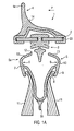
- the wiper blade 1 each show a wiper blade 1 with an elongated elastic support element 2 of two parallel spring steel blades, between which a wiper strip 3 is clamped. Details of this embodiment are the EP 1 597 120 and the two priority applications relating to this European application, to which reference is made in the present case.
- the wiper blade 1 also comprises a wind deflector strip 4, which is provided on the upper side opposite the wiper strip 3 and mounted on the support element 2 and forms an inflow web 4a via a concave inflow face 14 in the direction of flow arrow P, which extends substantially perpendicular to the band-shaped support member 2.
- a protective rail 5 can also be seen in FIGS. 1A to 1C, which is configured symmetrically relative to the central longitudinal axis of the wiper strip 3 and forms a wiper blade receptacle 5a in its upper region, which at its lower, slightly tapering end a protective rail wiper strip 5b carries.
- the wiper blade receptacle 5a is formed from a thermoplastic, preferably hard elastic plastic and produced together with the protective rail wiper strip 5b formed by a soft elastic plastic by co-extrusion.
- two protective rails are produced in parallel by means of co-extrusion, namely with a soft-elastic, both wiper blade receptacles 5a connecting central part, which is severed centrally to form the respective protective wiper strips 5b to a wiper blade receptacle 5a.
- a protective rail 5 has an upper, pear-shaped diverging region for lateral enclosure of the support member 2 together with the surrounding the support member 2 edges of Windabweisang 4.
- the wiper blade receptacle 5a has a receiving area of maximum size 6, the top and bottom is limited by these inward superior walls of the wiper blade receptacle 5a.
- a receiving area 6 of this maximum size on the underside bounding wall 7 of the wiper blade receptacle 5 a bounds the upper side a downwardly open entrance pocket 8.
- the pocket 8 is bounded on the outside by a wall web 9, which is slightly inclined inwardly, but otherwise down substantially and continuously a Recording area 6 maximum size limiting wall section 10 continues. Between the wall web 9 and the wiper blade receiving 5a bounding wall is the upper side of the wall 7 limited pocket 8th
- spreading fingers 11 For mounting wiper blade 1 and protective rail 5, spreading fingers 11, which are shown only with their upper end in FIGS. 1A to 1C, enter the engagement pockets 9 from below.
- the spreading fingers 11 can be mounted so as to be translatable and / or pivotable relative to one another. In the embodiment shown, a translational mobility of the spreading fingers 11 in a direction perpendicular to the central longitudinal axis of the wiper strip 3 is indicated. After the spreading fingers 11 are inserted into the engaging pockets 8, the free ends of the respective engaging fingers 11 are spaced from each other.
- a receiving opening 12 to the wiper blade receiving 5a limiting contact webs 13 are spaced from each other until the position shown in Fig. 1 B maximum spread is reached. In this position are the aligned ends the contact webs 13 so far apart that the wiper blade 1 can be inserted with its widest point in the wiper blade receptacle 5a.
- the wiper blade 1 and the protective rail 5 are now placed on each other until the wiper blade 1 abuts against the receiving area 6 of maximum size on the underside of the limiting wall 7.
- the spreading fingers 11 are placed on each other. For this purpose, for example, an applied during spreading of the spreading fingers 11 elastic bias can be relieved.
- the end position is shown in Fig. 1C.
- the wiper blade receiving 5a bounding wall is curved slightly concave outward.
- the upper ends of the spreading fingers 11 are curved.
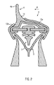
- a modified embodiment of a protective rail in which the contact webs are arranged asymmetrically.
- the longer front abutment web 13v is dimensioned so that it extends beyond the central longitudinal axis of the wiper strip 3 and can be applied to an inflow surface 14 which is formed by the Windabweisang 4 at its front in the direction of flow P part in the form of a concave outer surface.
- This embodiment allows a particularly secure anchoring of the protective rail 5 on the wiper blade 1 and increases the contact pressure between the contact web 13 and wiper blade 1, especially at higher speeds.
- the protective rail 5 with its receiving opening to form a width the wiper blade 1 are spread at its widest point crossing insertion opening, so that the wiper blade 1 can be introduced without contact in the protective rail 5 with its support member 2.
- the formation of pockets 8 and the associated motorized spreading of the guard rail also offers the advantage that the material of the guard rail can be concentrated in the neutral phase. Wiper blades are usually curved in a plane extending at right angles to the plane of the drawing of the figures. With increasing accumulation of material outside of the neutral fiber, in particular by the protective rail 5, there is the problem that the wiper blade unit can only be adapted insufficiently to the curved contour of the windshield of the vehicle.
- the protective rail wiper strip 5b In a surface contact of the protective rail wiper strip 5b to the windshield, it may come to detach the protective rail 5 of the wiper blade 1. This is avoided with the present invention, since the predominant, the guard rail 5 forming material can be concentrated in the neutral phase.
- the protective rail 5 and in particular the design and arrangement of the pockets 8 can be adapted for this purpose. The aim is to minimize the area moment of inertia of the wiper blade unit with respect to the bending axis of the wiper blade 1, which is justified by the additional material of the protective rail 5.
Landscapes
- Engineering & Computer Science (AREA)
- Physics & Mathematics (AREA)
- Fluid Mechanics (AREA)
- Quality & Reliability (AREA)
- Mechanical Engineering (AREA)
- Extrusion Moulding Of Plastics Or The Like (AREA)
- Cleaning In General (AREA)
- Wind Motors (AREA)
- Connection Of Plates (AREA)
Applications Claiming Priority (1)
| Application Number | Priority Date | Filing Date | Title |
|---|---|---|---|
| DE200620004584 DE202006004584U1 (de) | 2006-03-22 | 2006-03-22 | Wischblatt |
Publications (2)
| Publication Number | Publication Date |
|---|---|
| EP1837257A2 true EP1837257A2 (fr) | 2007-09-26 |
| EP1837257A3 EP1837257A3 (fr) | 2010-01-27 |
Family
ID=38068888
Family Applications (2)
| Application Number | Title | Priority Date | Filing Date |
|---|---|---|---|
| EP07005802A Withdrawn EP1837257A3 (fr) | 2006-03-22 | 2007-03-21 | Unité de raclette d'essuie-glace |
| EP07005803A Withdrawn EP1837258A3 (fr) | 2006-03-22 | 2007-03-21 | Raclette d'essuie-glace |
Family Applications After (1)
| Application Number | Title | Priority Date | Filing Date |
|---|---|---|---|
| EP07005803A Withdrawn EP1837258A3 (fr) | 2006-03-22 | 2007-03-21 | Raclette d'essuie-glace |
Country Status (2)
| Country | Link |
|---|---|
| EP (2) | EP1837257A3 (fr) |
| DE (1) | DE202006004584U1 (fr) |
Cited By (1)
| Publication number | Priority date | Publication date | Assignee | Title |
|---|---|---|---|---|
| US20120005855A1 (en) * | 2009-04-21 | 2012-01-12 | Valeo Systemes D'essuyage | Flat wiper blade |
Families Citing this family (2)
| Publication number | Priority date | Publication date | Assignee | Title |
|---|---|---|---|---|
| DE102011054123A1 (de) * | 2011-09-30 | 2013-04-04 | Valeo Wischersysteme Gmbh | Wischblatt zum Reinigen von Fahrzeugscheiben |
| DE102014209269A1 (de) | 2014-05-15 | 2015-11-19 | Volkswagen Aktiengesellschaft | Scheibenwischer |
Family Cites Families (11)
| Publication number | Priority date | Publication date | Assignee | Title |
|---|---|---|---|---|
| DE3637106A1 (de) * | 1986-10-31 | 1988-05-19 | Audi Ag | Scheibenwischer fuer ein kraftfahrzeug |
| US5732436A (en) * | 1995-08-21 | 1998-03-31 | Feigenbaum; Jeffery J. | Replacement wiper blade |
| DE19626532C2 (de) * | 1996-07-02 | 2002-10-24 | Bayerische Motoren Werke Ag | Schutzhülle für den Wischgummi eines Scheibenwischers |
| DE19935858A1 (de) * | 1999-07-30 | 2001-02-01 | Bosch Gmbh Robert | Wischblatt zum Reinigen von Scheiben an Kraftfahrzeugen |
| JP5009471B2 (ja) * | 2000-05-29 | 2012-08-22 | ローベルト ボツシユ ゲゼルシヤフト ミツト ベシユレンクテル ハフツング | 窓ガラス、殊に自動車の窓ガラスの清掃のためのワイパーブレード |
| DE10044913B4 (de) * | 2000-05-29 | 2017-10-05 | Robert Bosch Gmbh | Wischblatt zum Reinigen von Scheiben, insbesondere von Kraftfahrzeugen |
| DE10120467A1 (de) * | 2001-04-26 | 2002-10-31 | Bosch Gmbh Robert | Wischblatt zum Reinigen von Scheiben, insbesondere von Kraftfahrzeugen |
| WO2004076251A1 (fr) * | 2003-02-21 | 2004-09-10 | Robert Bosch Gmbh | Essuie-glace destine au nettoyage de vitres, notamment de vehicules automobiles |
| DE10335396A1 (de) | 2003-02-21 | 2004-10-07 | Robert Bosch Gmbh | Verfahren zum Herstellen eines Wischblatts sowie Vorrichtung zur Durchführung des Verfahrens und danach hergestelltes Wischblatt |
| US7464433B2 (en) * | 2003-03-21 | 2008-12-16 | Robert Bosch Gmbh | Wiper blade to clean windows, in particular of motor vehicles |
| DE102005037269A1 (de) * | 2005-02-03 | 2006-08-10 | Robert Bosch Gmbh | Wischblatt eines Scheibenwischers mit einer Schutzschiene |
-
2006
- 2006-03-22 DE DE200620004584 patent/DE202006004584U1/de not_active Expired - Lifetime
-
2007
- 2007-03-21 EP EP07005802A patent/EP1837257A3/fr not_active Withdrawn
- 2007-03-21 EP EP07005803A patent/EP1837258A3/fr not_active Withdrawn
Cited By (3)
| Publication number | Priority date | Publication date | Assignee | Title |
|---|---|---|---|---|
| US20120005855A1 (en) * | 2009-04-21 | 2012-01-12 | Valeo Systemes D'essuyage | Flat wiper blade |
| US9440621B2 (en) * | 2009-04-21 | 2016-09-13 | Valeo Systèmes d'Essuyage | Flat wiper blade |
| US10166952B2 (en) | 2009-04-21 | 2019-01-01 | Valeo Systèmes d'Essuyage | Flat wiper blade |
Also Published As
| Publication number | Publication date |
|---|---|
| EP1837257A3 (fr) | 2010-01-27 |
| DE202006004584U1 (de) | 2007-07-26 |
| EP1837258A3 (fr) | 2010-01-27 |
| EP1837258A2 (fr) | 2007-09-26 |
Similar Documents
| Publication | Publication Date | Title |
|---|---|---|
| DE10291817B4 (de) | Wischblatt zum Reinigen von Scheiben, insbesondere von Kraftfahrzeugen | |
| EP2015971B1 (fr) | Balai d'essuie-glace | |
| DE4439109B4 (de) | Mit einer Windleitvorrichtung komplettierbares Wischblatt | |
| EP1597120A1 (fr) | Essuie-glace destine au nettoyage de vitres, notamment de vehicules automobiles | |
| EP1597121A1 (fr) | Procede et dispositif de production d'un essuie-glace et essuie-glace ainsi obtenu | |
| EP0889813A1 (fr) | Balai d'essuie-glace pour systeme d'essuie-glace de vehicule | |
| DE69403683T2 (de) | Verbindungs-und Gelenkeinrichtung zur Befestigung eines Scheibenwischblatts an einem Wischarm | |
| EP1240061A1 (fr) | Balai d'essuie-glace | |
| DE69415254T3 (de) | Verbindungselement für Scheibenwischerblatt | |
| EP0477132B1 (fr) | Une unité de lame avec un element de soutien/guidage | |
| DE2550790A1 (de) | Abstreifeinrichtung fuer gleitbahnen an werkzeugmaschinen | |
| EP0691496A1 (fr) | Dispositif d'ancrage expansible | |
| DE3639537A1 (de) | Wischarm, insbesondere fuer kraftfahrzeuge | |
| EP0853564A1 (fr) | Lame d'essuie-glace pour vehicules a moteur | |
| DE3902399A1 (de) | Zierleistenhalter | |
| DE10007808B4 (de) | Wischblatt | |
| EP1837257A2 (fr) | Unité de raclette d'essuie-glace | |
| DE19626937A1 (de) | Vorrichtung zur Geräuschminderung an einer Schiebedachöffnung eines Fahrzeugs | |
| EP0889814A1 (fr) | Balai d'essuie-glace pour nettoyer des pare-brise de vehicules | |
| DE29903123U1 (de) | Scheibenwischer für Fahrzeuge aller Art | |
| DE10058455B4 (de) | Wischeranordnung und Verfahren zum Betreiben einer Wischeranordnung | |
| DE69516575T2 (de) | Befestigungselement für Kabel, Rohre oder dergleichen | |
| EP3956183B1 (fr) | Déflecteur d'air destiné à un système d'essuie-glace d'un véhicule automobile | |
| DE20120923U1 (de) | Abdeckung für einen Handbremshebelspalt eines Kraftfahrzeuges | |
| DE3823001A1 (de) | Wischblatt zum reinigen von insbesondere seitlich stark gewoelbten fahrzeugscheiben |
Legal Events
| Date | Code | Title | Description |
|---|---|---|---|
| PUAI | Public reference made under article 153(3) epc to a published international application that has entered the european phase |
Free format text: ORIGINAL CODE: 0009012 |
|
| AK | Designated contracting states |
Kind code of ref document: A2 Designated state(s): AT BE BG CH CY CZ DE DK EE ES FI FR GB GR HU IE IS IT LI LT LU LV MC MT NL PL PT RO SE SI SK TR |
|
| AX | Request for extension of the european patent |
Extension state: AL BA HR MK YU |
|
| PUAL | Search report despatched |
Free format text: ORIGINAL CODE: 0009013 |
|
| AK | Designated contracting states |
Kind code of ref document: A3 Designated state(s): AT BE BG CH CY CZ DE DK EE ES FI FR GB GR HU IE IS IT LI LT LU LV MC MT NL PL PT RO SE SI SK TR |
|
| AX | Request for extension of the european patent |
Extension state: AL BA HR MK RS |
|
| AKY | No designation fees paid | ||
| STAA | Information on the status of an ep patent application or granted ep patent |
Free format text: STATUS: THE APPLICATION IS DEEMED TO BE WITHDRAWN |
|
| 18D | Application deemed to be withdrawn |
Effective date: 20100728 |
|
| REG | Reference to a national code |
Ref country code: DE Ref legal event code: R108 Effective date: 20110201 Ref country code: DE Ref legal event code: 8566 |