EP1837268A2 - Châssis auxiliaire pour véhicules automobiles et procédé de montage d'un groupe motopropulseur sur un tel châssis auxiliaire - Google Patents
Châssis auxiliaire pour véhicules automobiles et procédé de montage d'un groupe motopropulseur sur un tel châssis auxiliaire Download PDFInfo
- Publication number
- EP1837268A2 EP1837268A2 EP06026013A EP06026013A EP1837268A2 EP 1837268 A2 EP1837268 A2 EP 1837268A2 EP 06026013 A EP06026013 A EP 06026013A EP 06026013 A EP06026013 A EP 06026013A EP 1837268 A2 EP1837268 A2 EP 1837268A2
- Authority
- EP
- European Patent Office
- Prior art keywords
- auxiliary frame
- frame
- subframe
- subframe according
- additional
- Prior art date
- Legal status (The legal status is an assumption and is not a legal conclusion. Google has not performed a legal analysis and makes no representation as to the accuracy of the status listed.)
- Granted
Links
Images


Classifications
-
- B—PERFORMING OPERATIONS; TRANSPORTING
- B62—LAND VEHICLES FOR TRAVELLING OTHERWISE THAN ON RAILS
- B62D—MOTOR VEHICLES; TRAILERS
- B62D21/00—Understructures, i.e. chassis frame on which a vehicle body may be mounted
- B62D21/11—Understructures, i.e. chassis frame on which a vehicle body may be mounted with resilient means for suspension, e.g. of wheels or engine; sub-frames for mounting engine or suspensions
-
- B—PERFORMING OPERATIONS; TRANSPORTING
- B60—VEHICLES IN GENERAL
- B60G—VEHICLE SUSPENSION ARRANGEMENTS
- B60G21/00—Interconnection systems for two or more resiliently-suspended wheels, e.g. for stabilising a vehicle body with respect to acceleration, deceleration or centrifugal forces
- B60G21/02—Interconnection systems for two or more resiliently-suspended wheels, e.g. for stabilising a vehicle body with respect to acceleration, deceleration or centrifugal forces permanently interconnected
- B60G21/04—Interconnection systems for two or more resiliently-suspended wheels, e.g. for stabilising a vehicle body with respect to acceleration, deceleration or centrifugal forces permanently interconnected mechanically
- B60G21/05—Interconnection systems for two or more resiliently-suspended wheels, e.g. for stabilising a vehicle body with respect to acceleration, deceleration or centrifugal forces permanently interconnected mechanically between wheels on the same axle but on different sides of the vehicle, i.e. the left and right wheel suspensions being interconnected
- B60G21/055—Stabiliser bars
- B60G21/0551—Mounting means therefor
-
- B—PERFORMING OPERATIONS; TRANSPORTING
- B60—VEHICLES IN GENERAL
- B60G—VEHICLE SUSPENSION ARRANGEMENTS
- B60G2204/00—Indexing codes related to suspensions per se or to auxiliary parts
- B60G2204/10—Mounting of suspension elements
- B60G2204/12—Mounting of springs or dampers
- B60G2204/122—Mounting of torsion springs
- B60G2204/1222—Middle mounts of stabiliser on vehicle body or chassis
-
- B—PERFORMING OPERATIONS; TRANSPORTING
- B60—VEHICLES IN GENERAL
- B60G—VEHICLE SUSPENSION ARRANGEMENTS
- B60G2204/00—Indexing codes related to suspensions per se or to auxiliary parts
- B60G2204/10—Mounting of suspension elements
- B60G2204/15—Mounting of subframes
-
- B—PERFORMING OPERATIONS; TRANSPORTING
- B60—VEHICLES IN GENERAL
- B60G—VEHICLE SUSPENSION ARRANGEMENTS
- B60G2206/00—Indexing codes related to the manufacturing of suspensions: constructional features, the materials used, procedures or tools
- B60G2206/01—Constructional features of suspension elements, e.g. arms, dampers, springs
- B60G2206/60—Subframe construction
- B60G2206/602—Single transverse beam
Definitions
- the invention relates to a subframe according to the preamble of claim 1, a vehicle body with a subframe mounted thereon according to claim 22, an adapter part for a subframe according to claim 23, and a method for assembling a drive unit on a subframe according to the preamble of claim 24 ,
- Subframe for motor vehicles which are also referred to as axle, are well known and are regularly bolted to the body via appropriate connection points.
- Such subframes can be used both in the area of the front axles as front axle auxiliary frame and in the region of the rear axles. '
- subframe for motor vehicles is from the EP 1 386 827 A2 known. Accordingly, the subframe is a closed frame with two side rails and two cross members and connected via damping bearings with the structure of the motor vehicle. A drive unit of the motor vehicle is supported in a three-point bearing via corresponding rubber bearings on the two cross members.
- the support base for the drive unit is designed sufficiently well with a three-point bearing.
- the three-point bearing can be supplemented with about two other bearings on the subframe.
- the additional bearings can support the front portion of the transmission of the drive unit.
- bending vibrations of the drive assembly are prevented, resulting in the case of a three-point bearing between the spaced apart in the direction of travel bearings in the drive unit.
- an improvement in the acoustic properties of such a five-point storage of the drive unit allows a more even distribution of the bearing forces while reducing the individual bearing forces.
- subframe For vehicles of low comfort class, therefore, on the one hand subframe must be provided, which allow a three-point bearing of the drive unit.
- specially designed subframes for premium vehicles are to be provided which, in addition to the three-point bearing, have additional bearing points. Consequently, different subframes must be maintained in a logistically complex manner.
- the object of the invention is to provide a subframe for motor vehicles, a vehicle body with mounted subframe, an adapter part for such a subframe, or a method for mounting a power plant on such a subframe in which a vehicle assembly is simplified.
- the subframe on a basic auxiliary frame which provides at least one auxiliary frame side bearing, which supports a drive unit together with at least one other auxiliary frame side and / or body side bearing.
- the basic auxiliary frame can be extended by means of an adapter part, which provides at least one additional storage location.
- the subframe is therefore used in its basic version for motor vehicles low comfort class.
- the basic auxiliary frame can be expanded with the adapter part and thus provide at least one additional bearing point, which additionally supports the drive unit.
- the basic auxiliary frame may have two bearing points, which together with a third, body-side bearing point form a three-point bearing.
- the third body-side bearing point can be provided on a traverse in the middle tunnel of the vehicle body.
- the internal combustion engine of the drive unit is mainly supported by the two auxiliary frame-side front bearings, while flanged behind the engine Transmission is supported by the body-side bearing point.
- This three-point support provided by the basic auxiliary frame is designed for low comfort vehicles.
- the basic auxiliary frame can be extended by the adapter part according to the invention, which provides at least one additional storage location.
- the additional bearing point can preferably be arranged between the already existing bearing points of the three-point bearing and approximately support the front portion of the transmission in addition.
- the bending vibrations arising between the already existing bearing points of the three-point bearing can be absorbed due to a longitudinal expansion of the drive assembly. From this bending vibrations resulting acoustic problems can therefore be avoided. Moreover, results with the additional bearing a more even distribution of the bearing forces while reducing the individual bearing forces.
- the subframe is used in its basic structure, regardless of the comfort class of the drive unit.
- the basic auxiliary frame can be mounted on the modular principle either with the adapter part for premium vehicles.
- the basic auxiliary frame can also be used without an adapter part for a vehicle with a low comfort class.
- a stiffening element can be mounted on the basic auxiliary frame. It is advantageous if the basic auxiliary frame has identical mounting brackets, to which optionally the adapter part or alternatively, a stiffening element is attachable.
- the basic auxiliary frame therefore has attachment brackets which can be used both for fastening the adapter part and the stiffening element.
- the above-mentioned mounting brackets can be recognized as bearing blocks on the outside of the side member of the basic auxiliary frame.
- the mounting brackets can also be welded in the form of a tubular pipe within the subframe side member.
- the adapter part can be an additional cross member which connects the respective subframe longitudinal members of the basic auxiliary frame. Due to the additional cross member, on the one hand, the additional bearing point is stably supported and, on the other hand, the rigidity of the subframe is increased.
- a closed and thus stable frame can be provided in a U-shaped, open-designed basic auxiliary frame with the additional cross member.
- the adapter part or the additional cross member together with stiffening struts form an independent stiffening assembly.
- this stiffening module can be identical to the stiffening element, which can alternatively be attached to the basic auxiliary frame. This ensures that that the stiffener assembly or, alternatively, the stiffener may use the identical mounting brackets on the basic subframe.
- the mounting brackets are designed so that both the stiffening assembly and the stiffening element can be fixed in the vehicle vertical axis direction on the bottom side of the basic auxiliary frame. This ensures easy accessibility in case of repair.
- the stiffening struts can be arranged like a truss. It is preferred in this case if the stiffening struts are brought together in a V-shape in the manner of a strut half-cross on a middle node part of the additional cross member.
- the stiffening struts of the strut half-cross may be identical to the corresponding reinforcing struts of the stiffening element.
- the additional crossbeam can be reinforced with side panel parts at both side ends.
- the side panel parts ensure a stable connection to the subframe side members.
- Each of these side node parts can be plate-shaped, shaped like a trapezoid, torsionally stiff.
- Each of these side knot parts in the event of a crash is a force flow node, via which forces are directed to the additional cross member.
- the side node parts of the additional cross member in the vehicle longitudinal direction may have a plurality of spaced-apart connection points for connection to the subframe side members.
- the at least one additional bearing can advantageously be arranged in a mounting section of the side node parts of the additional cross member.
- the above-described basic auxiliary frame can be provided with the at least one auxiliary frame-side bearing point in a first assembly step.
- This basic auxiliary frame can be used independently of the respective comfort class of the vehicle.
- An individualization of the basic auxiliary frame then takes place in a second assembly step:
- the basic auxiliary frame is extended with an adapter part which provides a supplementary storage point.
- the adapter part when using the basic auxiliary frame in a low comfort class vehicle, the adapter part is omitted, and instead, for example, a conventional stiffening element can be mounted to the basic auxiliary frame.
- the subframe according to the invention can be used both in the region of the front axles and rear axles. Likewise, the subframe according to the invention can be used in front-wheel drive, rear-wheel drive and also in all-wheel drive vehicles.
- the drive unit is in the case of a front-wheel drive motor vehicle, the internal combustion engine and the speed change gearbox with integrated front differential.
- the stiffening assembly and / or the strut cross can be composed of individual struts and individual node parts and welded together.
- the stiffening assembly and / or the cross strut may also be a bivalve construction, the one Deep-drawn sheet metal upper shell and a welded sheet metal lower shell.
- the struts manufacturing technology are already already uniform material and preformed in one piece in the upper shell or lower shell.
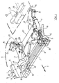
- an auxiliary frame 1 is shown as a front axle auxiliary frame.
- the subframe 1 carries a drive unit, not shown, having an internal combustion engine with associated speed change gearbox.
- the subframe 1 in the direction of travel indicated by the arrow I in the vehicle longitudinal direction, has two laterally opposite one another Subframe side members 3, 4 on. These are each connected at the front with node elements 5, which are box-shaped casting nodes 5 here. These cast nodes 5 connect the two subframe longitudinal members 3, 4 with a subframe cross member 7. In the direction of travel I front side in front of the subframe cross member 7 extends parallel to a stabilizer. 9
- the basic auxiliary frame 11 is a U-shaped, rear open frame.
- each of the subframe side members 3, 4 has respective rear handlebar consoles 13 formed immediately adjacent to rear body attachment points 15.
- Corresponding front handlebar consoles 17 are each formed in the casting node 5 according to FIG. 1 .
- a half-shell-shaped bearing bracket 19 for a drive unit bearing are provided on each of the two casting nodes 5 on the inside.
- the bearing brackets 19 are bolted to the cast nodes 5 via point-like screw connections 18.
- the subframe 1 is fastened with front, casting node-side attachment points 14 and with the rear body attachment points 15 to the longitudinal carrier 6 of a vehicle body indicated by dash-dotted lines in FIG .
- the two front bearing brackets 19 each limit as a bearing a cavity 20 in which an unillustrated bearing is to be used.
- the two front bearings 20 support together with a body-side Bearing point 21, the drive unit from.
- This body-side bearing 21 is arranged according to FIG. 1 in the region of an indicated central tunnel 23 on a cross-beam 25. On the body-side bearing 21 in particular the transmission of the drive unit is supported.
- the basic auxiliary frame 11 is extended by an adapter part formed as an additional cross member 27.
- the additional cross member 27 has frontally each have a plate-shaped side node portion 29.
- the side node portion 29 is designed roughly trapezoidal according to FIGS. 2 and 3 and widens in the direction of the subframe side members 3, 4.
- each side node portion 29 has two spaced apart in the direction of travel I, circularly indicated screw points 31, via which the additional cross member 27 is attached to two mounting brackets 33 of the subframe side members 3, 4.
- Each of the side node parts 29 of the additional cross member 27 has shown in FIG. 2 circular receiving openings, in each of which indicated additional bearings 35 are used, which represent corresponding additional bearing points for supporting a front portion of the transmission of the drive unit.
- the drive unit is supported in a five-point bearing on the subframe 1 and on the body. Bending vibrations, which result in a three-point bearing between the front two bearings 20 and the rear body-side bearing 21 due to a longitudinal expansion of the drive unit, can thus be absorbed by the two additional bearings 35.
- the additional cross member 27 forms together with truss-like arranged stiffening struts 37, 38 and 39, a compact stiffener assembly 41.
- This assembly 41 is shown in the exploded view of FIG. 3 in isolation.
- the stiffening struts 37 are therefore brought together in a V-shape in the manner of a strut half-cross on a middle node part 43 of the additional cross member 27.
- the strut ends of the V-shaped arranged stiffening struts 37 are connected to each other via longitudinal struts 38 and a transverse strut 39. Overall, the struts 37, 38, 39 therefore form a torsionally rigid closed rectangular frame structure with the additional cross member 27.
- stiffening assembly 41 forms an inner closed frame.
- the basic auxiliary frame 11 together with the additional cross member 27 an outer closed frame.
- Both the inner frame and the outer frame have with the additional cross member 27 on a common frame side.
- the stiffener assembly 41 on the opposite side has respective corner node parts 45 with attachment points 47 to connect the stiffener assembly 41 to the outer frame, i. H. to screw with corresponding connection points 48 of the cast nodes 5 of the subframe 1.
- An individualization of the basic auxiliary frame 11 takes place in the second assembly step with the decision as to whether the stiffening assembly 41 or instead of the stiffening element 49 is to be mounted on the basic auxiliary frame 11.
- the basic auxiliary frame 11 is expanded with the stiffening module 41 carrying the adapter part 27.
- the two additional bearings 35 are provided, which also support the drive unit in the region of its transmission.
- the stiffening assembly 41 is connected on the bottom side in the vehicle vertical axis direction from below to the basic auxiliary frame 11.
- the side node parts 29 of the additional cross member 27 are screwed to the corresponding mounting brackets 33 of the subframe side members 3, 4.
- the front corner node portions 45 of the stiffener assembly 41 are bolted to the front mounting brackets 17.
- the stiffening assembly 41 can be dispensed with.
- a stiffening element 49 may be used.
- the stiffening element 49 is shown in FIG. 3 a four-armed strut cross with truss-like arranged struts 37, 38, 39th
- both the stiffening assembly 41 and the strut cross 49 are constructed identically.
- the itarmenden the strut cross 49 are also connected via the corner node parts 45 with the longitudinal struts 38 and the cross brace 39.
- the corner node parts 45 of the strut cross have - as well as the stiffening assembly 41 - as attachment points the screw holes 47, about the strut cross 49 to the rear mounting brackets 33 of the basic auxiliary frame 11 and to the front mounting brackets 17 can be mounted. That is, both the strut cross 49 and the stiffening assembly 41 can each be connected to identical mounting brackets 17, 33.
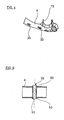
- the mounting brackets 33 of the subframe longitudinal members 3 and 4 are welded as bearing blocks outside circumference of the subframe side members 3, 4. Instead of these bearing blocks are in accordance with the modification shown in Figs. 4 and 5 as mounting brackets tubular pipes 51 in through holes 53 of the longitudinal members 3, 4 used and welded.
- an immediate and stable connection of the strut cross 49 or the stiffening assembly 41 - without the interposition of a radially from the subframe side members 3, 4 projecting bearing block - on the side rails 3, 4 allows.
- mounting the strut cross 49 or the stiffening assembly 41 screws are guided from below through the screw 31, 47 of the strut cross 49 or the stiffening assembly 41. Subsequently, the screws are passed through the tubular pipes 51 and screwed by means of fastening nuts.
Landscapes
- Engineering & Computer Science (AREA)
- Mechanical Engineering (AREA)
- Chemical & Material Sciences (AREA)
- Combustion & Propulsion (AREA)
- Transportation (AREA)
- Body Structure For Vehicles (AREA)
- Motor Power Transmission Devices (AREA)
- Arrangement Or Mounting Of Propulsion Units For Vehicles (AREA)
Applications Claiming Priority (1)
| Application Number | Priority Date | Filing Date | Title |
|---|---|---|---|
| DE200610013550 DE102006013550A1 (de) | 2006-03-24 | 2006-03-24 | Hilfsrahmen für Kraftfahrzeuge, Fahrzeugkarosserie mit einem daran montiertem Hilfsrahmen, Adapterteil für einen Hilfsrahmen sowie Verfahren zur Montage eines Antriebsaggregats auf einem solchen Hilfsrahmen |
Publications (3)
| Publication Number | Publication Date |
|---|---|
| EP1837268A2 true EP1837268A2 (fr) | 2007-09-26 |
| EP1837268A3 EP1837268A3 (fr) | 2008-05-14 |
| EP1837268B1 EP1837268B1 (fr) | 2011-11-23 |
Family
ID=37698103
Family Applications (1)
| Application Number | Title | Priority Date | Filing Date |
|---|---|---|---|
| EP20060026013 Ceased EP1837268B1 (fr) | 2006-03-24 | 2006-12-15 | Châssis auxiliaire pour véhicules automobiles et procédé de montage d'un groupe motopropulseur sur un tel châssis auxiliaire |
Country Status (2)
| Country | Link |
|---|---|
| EP (1) | EP1837268B1 (fr) |
| DE (1) | DE102006013550A1 (fr) |
Cited By (9)
| Publication number | Priority date | Publication date | Assignee | Title |
|---|---|---|---|---|
| DE102012103125A1 (de) * | 2012-04-12 | 2013-10-17 | Dr. Ing. H.C. F. Porsche Aktiengesellschaft | Trägerstruktur für eine Antriebsachsenanordnung eines Kraftfahrzeuges sowie eine Antriebsachsenanordnung |
| EP2860085A1 (fr) | 2013-10-10 | 2015-04-15 | Audi Ag | Châssis auxiliaire pour un véhicule automobile |
| EP2457807A3 (fr) * | 2010-11-25 | 2016-01-20 | Audi AG | Berceau de véhicule automobile |
| CN106553520A (zh) * | 2015-09-28 | 2017-04-05 | 长城汽车股份有限公司 | 发动机后悬置组合模块和汽车前副车架组装总成 |
| CN108016498A (zh) * | 2017-12-15 | 2018-05-11 | 阿尔特汽车技术股份有限公司 | 模块化钢铝混合副车架结构 |
| US20190135063A1 (en) * | 2017-11-07 | 2019-05-09 | Volvo Car Corporation | System for wheel suspension of a vehicle |
| CN109760744A (zh) * | 2019-03-11 | 2019-05-17 | 汉腾汽车有限公司 | 一种后副车架加强结构 |
| CN113771948A (zh) * | 2021-08-25 | 2021-12-10 | 重庆长安汽车股份有限公司 | 一种下车身前部结构 |
| EP4339074A1 (fr) * | 2022-09-12 | 2024-03-20 | FERRARI S.p.A. | Véhicule automobile muni d'une structure de renfort |
Families Citing this family (18)
| Publication number | Priority date | Publication date | Assignee | Title |
|---|---|---|---|---|
| DE102008006006B4 (de) * | 2008-01-25 | 2023-12-14 | Dr. Ing. H.C. F. Porsche Aktiengesellschaft | Hilfsrahmen |
| DE102008019593B4 (de) * | 2008-04-18 | 2023-08-03 | Bayerische Motoren Werke Aktiengesellschaft | Hilfsrahmen im Fahrwerksbereich eines zweispurigen Fahrzeugs |
| DE102009029883A1 (de) * | 2009-06-23 | 2010-12-30 | Bayerische Motoren Werke Aktiengesellschaft | Achsträger für ein Kraftfahrzeug |
| DE102009041771A1 (de) † | 2009-09-16 | 2011-03-17 | Volkswagen Ag | Hilfsrahmen für ein Kraftfahrzeug |
| DE102010009506A1 (de) * | 2010-02-26 | 2011-09-01 | Volkswagen Ag | Momentensteifer Fahrwerkhilfsrahmen eines Kraftfahrzeuges |
| DE102011102116A1 (de) * | 2011-05-20 | 2012-11-22 | GM Global Technology Operations LLC (n. d. Gesetzen des Staates Delaware) | Crashstruktur zur Anbindung an einen Vorderhilfsrahmen für ein Kraftfahrzeug |
| DE102011086338B4 (de) | 2011-11-15 | 2016-11-10 | Bayerische Motoren Werke Aktiengesellschaft | Achsträger für zweispurige Fahrzeuge |
| DE102012020612A1 (de) | 2012-10-19 | 2014-04-24 | Audi Ag | Achsträger für ein Kraftfahrzeug |
| DE102012021562B4 (de) | 2012-11-02 | 2023-06-29 | Volkswagen Aktiengesellschaft | Hilfsrahmen für ein Kraftfahrzeug |
| DE102013007976B4 (de) | 2013-05-10 | 2020-07-02 | Audi Ag | Hilfsrahmen für ein Kraftfahrzeug |
| DE102014206087A1 (de) * | 2014-03-31 | 2015-10-01 | Bayerische Motoren Werke Aktiengesellschaft | Knotenelement für einen Achsträger |
| DE102014017442A1 (de) * | 2014-11-22 | 2016-05-25 | Daimler Ag | Baukastensystem für eine Achsträgerstruktur eines Kraftwagens |
| DE102015004465B4 (de) * | 2015-04-04 | 2018-09-06 | Audi Ag | Zweispuriges Fahrzeug |
| DE102016206646A1 (de) | 2015-05-21 | 2016-11-24 | Ford Global Technologies, Llc | Hilfsrahmen für ein Fahrzeug |
| DE102016203173A1 (de) * | 2016-02-29 | 2017-08-31 | Bayerische Motoren Werke Aktiengesellschaft | Verstärkungsrahmen für ein Kraftfahrzeug und hiermit ausgestattetes Kraftfahrzeug |
| DE102017220095B4 (de) | 2017-11-10 | 2026-03-19 | Volkswagen Aktiengesellschaft | Vorderachshilfsrahmen mit einer Lagerung für eine Antriebseinheit |
| DE102020105300B3 (de) * | 2020-02-28 | 2021-02-18 | Bayerische Motoren Werke Aktiengesellschaft | Baukastensystem zur Herstellung von Bauvarianten eines Personenkraftwagens |
| DE102020113627B4 (de) | 2020-05-20 | 2026-02-26 | Bayerische Motoren Werke Aktiengesellschaft | Vorderwagenstruktur für einen Personenkraftwagen sowie Personenkraftwagen |
Citations (5)
| Publication number | Priority date | Publication date | Assignee | Title |
|---|---|---|---|---|
| US4392545A (en) | 1980-04-12 | 1983-07-12 | Toyo Kogyo Co., Ltd. | Engine mounting structure for an automobile body |
| DE3942794A1 (de) | 1989-12-23 | 1991-07-04 | Bayerische Motoren Werke Ag | Rahmenanordnung fuer ein kraftfahrzeug |
| DE19923693A1 (de) | 1999-05-22 | 2000-11-23 | Volkswagen Ag | Vollhilfsrahmen |
| EP0941912B1 (fr) | 1998-03-09 | 2002-05-02 | Bayerische Motoren Werke Aktiengesellschaft | Véhicule à moteur comportant un élément de renfort en forme de plaque |
| EP1386827A2 (fr) | 2002-08-01 | 2004-02-04 | Audi Ag | Châssis auxiliaire pour véhicules automobiles |
Family Cites Families (6)
| Publication number | Priority date | Publication date | Assignee | Title |
|---|---|---|---|---|
| JP2657319B2 (ja) * | 1989-08-08 | 1997-09-24 | 本田技研工業株式会社 | 自動車のパワーユニット支持装置 |
| DE10301910B3 (de) * | 2003-01-17 | 2004-06-17 | Voith Turbo Gmbh & Co. Kg | Rahmen |
| US7273230B2 (en) * | 2004-05-05 | 2007-09-25 | Toyota Technical Center Usa, Inc. | Tension shackle x-brace |
| DE502005002492D1 (de) * | 2005-02-11 | 2008-02-21 | Audi Ag | Hilfsrahmen für Kraftfahrzeuge |
| DE102005055978A1 (de) * | 2005-11-22 | 2007-05-24 | Benteler Automobiltechnik Gmbh | Hilfsrahmen für ein Kraftfahrzeug |
| DE102006009289A1 (de) * | 2006-03-01 | 2007-10-04 | Audi Ag | Hilfsrahmen zur Befestigung an einer Karosserie eines Kraftwagens |
-
2006
- 2006-03-24 DE DE200610013550 patent/DE102006013550A1/de not_active Withdrawn
- 2006-12-15 EP EP20060026013 patent/EP1837268B1/fr not_active Ceased
Patent Citations (5)
| Publication number | Priority date | Publication date | Assignee | Title |
|---|---|---|---|---|
| US4392545A (en) | 1980-04-12 | 1983-07-12 | Toyo Kogyo Co., Ltd. | Engine mounting structure for an automobile body |
| DE3942794A1 (de) | 1989-12-23 | 1991-07-04 | Bayerische Motoren Werke Ag | Rahmenanordnung fuer ein kraftfahrzeug |
| EP0941912B1 (fr) | 1998-03-09 | 2002-05-02 | Bayerische Motoren Werke Aktiengesellschaft | Véhicule à moteur comportant un élément de renfort en forme de plaque |
| DE19923693A1 (de) | 1999-05-22 | 2000-11-23 | Volkswagen Ag | Vollhilfsrahmen |
| EP1386827A2 (fr) | 2002-08-01 | 2004-02-04 | Audi Ag | Châssis auxiliaire pour véhicules automobiles |
Cited By (15)
| Publication number | Priority date | Publication date | Assignee | Title |
|---|---|---|---|---|
| EP2457807A3 (fr) * | 2010-11-25 | 2016-01-20 | Audi AG | Berceau de véhicule automobile |
| DE102012103125A1 (de) * | 2012-04-12 | 2013-10-17 | Dr. Ing. H.C. F. Porsche Aktiengesellschaft | Trägerstruktur für eine Antriebsachsenanordnung eines Kraftfahrzeuges sowie eine Antriebsachsenanordnung |
| EP2860085A1 (fr) | 2013-10-10 | 2015-04-15 | Audi Ag | Châssis auxiliaire pour un véhicule automobile |
| DE102013016758A1 (de) | 2013-10-10 | 2015-04-16 | Audi Ag | Hilfsrahmen für ein Kraftfahrzeug |
| CN104554446A (zh) * | 2013-10-10 | 2015-04-29 | 奥迪股份公司 | 用于机动车的副车架 |
| US9434416B2 (en) | 2013-10-10 | 2016-09-06 | Audi Ag | Subframe for a motor vehicle |
| CN106553520A (zh) * | 2015-09-28 | 2017-04-05 | 长城汽车股份有限公司 | 发动机后悬置组合模块和汽车前副车架组装总成 |
| US20190135063A1 (en) * | 2017-11-07 | 2019-05-09 | Volvo Car Corporation | System for wheel suspension of a vehicle |
| US11001112B2 (en) * | 2017-11-07 | 2021-05-11 | Volvo Car Corporation | System for wheel suspension of a vehicle |
| CN108016498A (zh) * | 2017-12-15 | 2018-05-11 | 阿尔特汽车技术股份有限公司 | 模块化钢铝混合副车架结构 |
| CN109760744A (zh) * | 2019-03-11 | 2019-05-17 | 汉腾汽车有限公司 | 一种后副车架加强结构 |
| CN113771948A (zh) * | 2021-08-25 | 2021-12-10 | 重庆长安汽车股份有限公司 | 一种下车身前部结构 |
| CN113771948B (zh) * | 2021-08-25 | 2023-12-12 | 深蓝汽车科技有限公司 | 一种下车身前部结构 |
| EP4339074A1 (fr) * | 2022-09-12 | 2024-03-20 | FERRARI S.p.A. | Véhicule automobile muni d'une structure de renfort |
| US12084111B2 (en) | 2022-09-12 | 2024-09-10 | Ferrari S.P.A. | Motor vehicle provided with a reinforcing structure |
Also Published As
| Publication number | Publication date |
|---|---|
| EP1837268B1 (fr) | 2011-11-23 |
| EP1837268A3 (fr) | 2008-05-14 |
| DE102006013550A1 (de) | 2007-09-27 |
Similar Documents
| Publication | Publication Date | Title |
|---|---|---|
| EP1837268B1 (fr) | Châssis auxiliaire pour véhicules automobiles et procédé de montage d'un groupe motopropulseur sur un tel châssis auxiliaire | |
| EP1690779B1 (fr) | Châssis auxiliaire pour véhicules automobiles | |
| DE102004028161B4 (de) | Unterfahrschutz für Personenkraftfahrzeuge zur Anordnung unter Längsträgerniveau vor einem Hilfsrahmen oder Achsträger als zusätzliche Crashebene | |
| EP1829767B1 (fr) | Cadre auxiliaire pour monter à la carrosserie d'un véhicule automobile | |
| EP0941912B1 (fr) | Véhicule à moteur comportant un élément de renfort en forme de plaque | |
| DE60104437T2 (de) | Modularer hilfsrahmen | |
| EP1816055B1 (fr) | Traverse de support pour tableau de bord de véhicule | |
| DE102006013548C5 (de) | Als Fahrschemel ausgebildeter Hilfsrahmen für Kraftfahrzeuge sowie Fahrzeugkarosserie | |
| EP2457807B1 (fr) | Berceau de véhicule automobile | |
| EP1787894B1 (fr) | Cadre auxiliaire de véhicule automobile | |
| DE102012005561B4 (de) | Hilfsrahmen für ein Kraftfahrzeug | |
| EP2477875B1 (fr) | Chassis auxiliaire pour un vehicule automobile | |
| DE102010011320A1 (de) | Vorderwagen eines Fahrzeugs | |
| EP1318064B1 (fr) | Châssis modulaire pour un camion | |
| DE102010020304A1 (de) | Hilfsträger | |
| EP0591715A2 (fr) | Véhicule utilitaire, en particulier camion avec cabine à l'avant | |
| DE102013011546A1 (de) | Hilfsrahmen für ein Kraftfahrzeug | |
| EP1321351A2 (fr) | Structure avant de véhicule automobile | |
| EP3911556A1 (fr) | Support d'essieu pour véhicule à moteur et sa fabrication | |
| DE102012020612A1 (de) | Achsträger für ein Kraftfahrzeug | |
| DE102006017225B4 (de) | Hilfsrahmen für Kraftfahrzeuge | |
| DE102011002964A1 (de) | Lagerung eines Querstabilisators an einem rahmenartigen Achsträger eines zweispurigen Fahrzeugs | |
| DE102006013547B4 (de) | Hilfsrahmen für Kraftfahrzeuge sowie ein Verfahren zur Montage von Antriebsaggregaten von Kraftfahrzeugen auf solchen Hilfsrahmen | |
| DE102016214463A1 (de) | Lagerungsanordnung für eine Lenksäule eines Fahrzeugs und Fahrzeug mit einer derartigen Lagerungsanordnung | |
| DE102005061417A1 (de) | Hilfsrahmen für ein Kraftfahrzeug |
Legal Events
| Date | Code | Title | Description |
|---|---|---|---|
| PUAI | Public reference made under article 153(3) epc to a published international application that has entered the european phase |
Free format text: ORIGINAL CODE: 0009012 |
|
| AK | Designated contracting states |
Kind code of ref document: A2 Designated state(s): AT BE BG CH CY CZ DE DK EE ES FI FR GB GR HU IE IS IT LI LT LU LV MC NL PL PT RO SE SI SK TR |
|
| AX | Request for extension of the european patent |
Extension state: AL BA HR MK YU |
|
| PUAL | Search report despatched |
Free format text: ORIGINAL CODE: 0009013 |
|
| AK | Designated contracting states |
Kind code of ref document: A3 Designated state(s): AT BE BG CH CY CZ DE DK EE ES FI FR GB GR HU IE IS IT LI LT LU LV MC NL PL PT RO SE SI SK TR |
|
| AX | Request for extension of the european patent |
Extension state: AL BA HR MK RS |
|
| 17P | Request for examination filed |
Effective date: 20081114 |
|
| 17Q | First examination report despatched |
Effective date: 20081230 |
|
| AKX | Designation fees paid |
Designated state(s): DE FR GB IT |
|
| GRAP | Despatch of communication of intention to grant a patent |
Free format text: ORIGINAL CODE: EPIDOSNIGR1 |
|
| GRAA | (expected) grant |
Free format text: ORIGINAL CODE: 0009210 |
|
| GRAS | Grant fee paid |
Free format text: ORIGINAL CODE: EPIDOSNIGR3 |
|
| AK | Designated contracting states |
Kind code of ref document: B1 Designated state(s): DE FR GB IT |
|
| REG | Reference to a national code |
Ref country code: GB Ref legal event code: FG4D Free format text: NOT ENGLISH |
|
| REG | Reference to a national code |
Ref country code: DE Ref legal event code: R096 Ref document number: 502006010632 Country of ref document: DE Effective date: 20120119 |
|
| PLBE | No opposition filed within time limit |
Free format text: ORIGINAL CODE: 0009261 |
|
| STAA | Information on the status of an ep patent application or granted ep patent |
Free format text: STATUS: NO OPPOSITION FILED WITHIN TIME LIMIT |
|
| 26N | No opposition filed |
Effective date: 20120824 |
|
| REG | Reference to a national code |
Ref country code: DE Ref legal event code: R097 Ref document number: 502006010632 Country of ref document: DE Effective date: 20120824 |
|
| REG | Reference to a national code |
Ref country code: FR Ref legal event code: PLFP Year of fee payment: 10 |
|
| REG | Reference to a national code |
Ref country code: FR Ref legal event code: PLFP Year of fee payment: 11 |
|
| REG | Reference to a national code |
Ref country code: FR Ref legal event code: PLFP Year of fee payment: 12 |
|
| PGFP | Annual fee paid to national office [announced via postgrant information from national office to epo] |
Ref country code: GB Payment date: 20181220 Year of fee payment: 13 Ref country code: FR Payment date: 20181221 Year of fee payment: 13 |
|
| PGFP | Annual fee paid to national office [announced via postgrant information from national office to epo] |
Ref country code: IT Payment date: 20181231 Year of fee payment: 13 Ref country code: DE Payment date: 20181231 Year of fee payment: 13 |
|
| REG | Reference to a national code |
Ref country code: DE Ref legal event code: R119 Ref document number: 502006010632 Country of ref document: DE |
|
| GBPC | Gb: european patent ceased through non-payment of renewal fee |
Effective date: 20191215 |
|
| PG25 | Lapsed in a contracting state [announced via postgrant information from national office to epo] |
Ref country code: FR Free format text: LAPSE BECAUSE OF NON-PAYMENT OF DUE FEES Effective date: 20191231 Ref country code: GB Free format text: LAPSE BECAUSE OF NON-PAYMENT OF DUE FEES Effective date: 20191215 Ref country code: IT Free format text: LAPSE BECAUSE OF NON-PAYMENT OF DUE FEES Effective date: 20191215 Ref country code: DE Free format text: LAPSE BECAUSE OF NON-PAYMENT OF DUE FEES Effective date: 20200701 |