EP1837458A2 - Stütze für die Verschalung von Platten oder Ähnlichem - Google Patents
Stütze für die Verschalung von Platten oder Ähnlichem Download PDFInfo
- Publication number
- EP1837458A2 EP1837458A2 EP07354018A EP07354018A EP1837458A2 EP 1837458 A2 EP1837458 A2 EP 1837458A2 EP 07354018 A EP07354018 A EP 07354018A EP 07354018 A EP07354018 A EP 07354018A EP 1837458 A2 EP1837458 A2 EP 1837458A2
- Authority
- EP
- European Patent Office
- Prior art keywords
- pin
- locking
- strut
- overmoulding
- locking pin
- Prior art date
- Legal status (The legal status is an assumption and is not a legal conclusion. Google has not performed a legal analysis and makes no representation as to the accuracy of the status listed.)
- Withdrawn
Links
Images



Classifications
-
- E—FIXED CONSTRUCTIONS
- E04—BUILDING
- E04G—SCAFFOLDING; FORMS; SHUTTERING; BUILDING IMPLEMENTS OR AIDS, OR THEIR USE; HANDLING BUILDING MATERIALS ON THE SITE; REPAIRING, BREAKING-UP OR OTHER WORK ON EXISTING BUILDINGS
- E04G25/00—Shores or struts; Chocks
- E04G25/04—Shores or struts; Chocks telescopic
- E04G25/06—Shores or struts; Chocks telescopic with parts held together by positive means
-
- E—FIXED CONSTRUCTIONS
- E04—BUILDING
- E04G—SCAFFOLDING; FORMS; SHUTTERING; BUILDING IMPLEMENTS OR AIDS, OR THEIR USE; HANDLING BUILDING MATERIALS ON THE SITE; REPAIRING, BREAKING-UP OR OTHER WORK ON EXISTING BUILDINGS
- E04G25/00—Shores or struts; Chocks
- E04G25/04—Shores or struts; Chocks telescopic
- E04G25/06—Shores or struts; Chocks telescopic with parts held together by positive means
- E04G25/061—Shores or struts; Chocks telescopic with parts held together by positive means by pins
Definitions
- a vertical support stay for the formwork of flat panels, slabs or the like, conventionally comprises a fixed rod placed on the ground cooperating with a sliding rod mounted in translation inside the rod. fixed, to adjust the height of the forestay.
- a first rough adjustment of the height of the strut consists of inserting a locking pin in a hole of the sliding rod, corresponding to the desired height of the strut. The locking pin is then in a first locking position, allowing the immobilization of the sliding rod in the fixed rod.
- a second fine adjustment is to actuate a clamping sleeve, surrounding the fixed shaft of the forestay. It is then in a first formwork position, in which it is immobile and unmountable.
- the invention aims to overcome the aforementioned drawbacks and is intended to provide a support strut for quickly and effortlessly moving from a formwork position to a stripping position, by removing the forces applied to the stay, allowing a rapid disassembly of the forestay, while minimizing the noise generated.
- the locking pin comprises an overmoulding of polymeric material substantially covering the whole of the pin, with the exception of the triggering member. automatic.
- the support strut 10 according to the invention is particularly intended for the formwork of panels, slabs or the like, in the field of construction and building.
- the support stay 10 comprises a shaft 11, constituting the fixed shaft of the strut 10, provided with a foot 12, for positioning the strut 10 on the ground.
- the support stay 10 also comprises a slide 13, constituting the sliding rod of the stay 10, mounted in translation in the barrel 11 and extended by a head 14.
- the stay 10 also comprises a clamping sleeve 15, surrounding the barrel 11 and cooperating with the barrel 11 to completely immobilize the strut 10 by clamping, in a first formwork position.
- the stay 10 is preferably of the protected thread type or may be, for example, of the apparent thread type.
- the support stay 10 comprises a locking pin 16, which can cooperate with a plurality of orifices 17, completely through the slide 13 ( Figures 1 and 3).
- the locking pin 16 is intended to lock the position of the slide 13 in the barrel 11, before the complete tightening of the strut 10 in the first formwork position.
- the desired length L1 of the stay 10, in formwork position ( Figure 1), therefore depends on the orifice 17 in which the pin 16 is introduced.
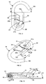
- the locking pin 16 is shaped as an open ring, of substantially circular section, comprising a first end 16a, intended to be introduced into an orifice 17 of the slide 13, and a second free end 16b, preferably curved towards the first end 16a ( Figure 5).
- the free end 16b of the pin 16 is offset relative to the first end 16a, which cooperates with the slide 13.
- the pin 16 is of circular section, with a diameter D of about 14 mm ( Figure 7), length L3 of the order of 209 mm and width L4 of the order of 135 mm ( Figure 6).
- the locking pin 16 has a flat portion 18, extending along the entire length of the first end 16a of the pin 16 (FIG. 5), so as to have a length substantially equal to or greater than the width of the slide 13 (FIGS. 1 to 4).
- the flat 18 opens substantially at the curve formed by the pin 16 ( Figure 5) ring-shaped.
- the maximum thickness of the flat 18 is of the order of 2.5 mm to 3 mm, at the diameter of the pin 16.
- FIG. 7 the remaining thickness e1 of the free end 16a of the pin 16 is therefore of the order of 11 mm to 11.5 mm, at the diameter D of the pin 16.
- the flat part 18 constitutes an automatic triggering member for the locking pin 16, intended to move the pin 16 from its locking position, corresponding to the first formwork position of the strut 10 (FIGS. 1 and 2), towards a second unlocking position, in which it discharges the strut 10 of the forces generated by the formwork position ( Figures 3 and 4).
- Unlocking the pin 16 simultaneously and automatically drives the stay 10 to a second stripping position, shown in FIGS. 3 and 4.
- the length L2 of the strut 10, in the stripping position is then less than the length L1 forestay 10, in formwork position ( Figures 1 and 2).
- the automatic unlocking of the pin 16 makes it possible to easily and quickly dismount the strut 10 without any wear, for later reuse.
- the pin 16 comprises a tongue 19 constituting an abutment member of the pin 16.
- the tongue 19 makes it possible to accurately position the pin 16 in its locking position in the slide 13 (FIG. ).
- the tongue 19 protrudes transversely from the pin 16, at the portion of the flat 18 furthest from the first end 16a.
- the tongue 19 is substantially flat, preferably welded to the pin 16, with a thickness e2 of the order of 3 mm (FIG. 7), a length L5 of the order of 40 mm and a width L6 of the order of 40mm ( Figure 6).
- the flat 18 is oriented relative to the plane of the pin 16, in the counterclockwise direction, an angle X1 of the order of 125 ° ( Figure 7).
- the tab 19 stop is oriented relative to the flat portion 18, in the counterclockwise direction, an angle X2 of the order of 113 °.
- the particular orientation of the flat part 18 and the tongue 19, with respect to the general orientation of the pin 16, makes it possible in particular to position the pin 16 substantially horizontally, in its locking position shown in FIGS. 1 and 2 , the flat 18 being then oriented in the direction of the strut 10, namely substantially vertically ( Figures 1 and 2).
- the support strut 10 is in its formwork position and has a length L1. maximum, in which it completely blocks the element to form.
- the pin 16 In this first shuttering position of the strut 10, the pin 16 is in its locking position, substantially horizontally, the tongue 19 being in abutment against the sleeve 15 of the barrel 11.
- the flat 18 is substantially vertical , in the direction of the strut 10, so that the height H1 of the first end 16a of the pin 16, in the corresponding orifice 17 of the slide 13, substantially corresponds to the diameter D of the pin 16.
- the support strut 10 is in its stripping position and has a length L2 less than the length L1 ( Figure 1).
- the body of the pin 16 is raised upwards and the pin 16 is in its unlocking position.
- the flat part 18 constituting the triggering member automatic pin 16 is now substantially parallel to the sleeve 15, facing it substantially horizontally.
- the height H2 of the first end 16a is less than the height H1 ( Figure 2), of the order of a few millimeters. Unlocking the pin 16 has caused the lowering of the head 14 of the strut 10, so as to release the forces exerted on the strut 10 and pass the strut 10 in its stripping position. This then results in the disengagement and release of the forestay 10 and rapid disassembly thereof, effortlessly and without any wear.
- the unlocking position of the pin 16 is advantageously obtained by applying a simple hammer blow on the body of the pin 16, towards the head 14 of the strut 10. This then results in a rotation of the first end 16a of the pin 16 inside the corresponding orifice 17, until the automatic positioning of the flat 18 opposite the sleeve 15, substantially horizontally.
- the support strut 10 is distinguished from the support strut 10 shown in FIGS. 1 to 7 by the structure of the locking pin 16 and by its abutment member.
- the locking pin 16 is shaped according to the same basic shape substantially in an open ring, comprising a first end 16a intended to be introduced into an orifice 17 of the slide 13, and a second end 16b free curved toward the first end 16a.
- Locking pin 16 has an overmoulding 20 of polymeric material substantially covering all of pin 16, with the exception of its first end 16a on which is formed the flat part 18.
- the overmolding 20 surrounds and covers, preferably completely, the free end 16b of the pin 16 and has a free end 20a ( Figures 9 and 10), stopping at the flat portion 18, at a distance L7 substantially corresponding to the diameter of the slide 13 ( Figure 9).
- Overmolding 20 is particularly intended to significantly reduce the noise generated by the handling of the pin 16 and the strut 10, especially when using a hammer to pass the pin 16 in its second unlocked position.
- the overmoulding 20 comprises a rigid filler rib 21 extending transversely in a part of the space delimited by the ends 16a and 16b of the pin 16, so as to fill the U-shaped bend formed by the pin 16 in the form of a ring, until it is substantially adjacent to the flat part 18.
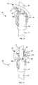
- the filling rib 21 thus forms an abutment member, intended to cooperate with the support strut 10, during the installation of the pin 16 in its first locking position, coming to be placed horizontally at the upper end of the sleeve 15 of the strut 10 ( Figures 11 and 12).
- the filling rib 21 has a free edge 21a, preferably slightly rounded, so as to cooperate with the slide 13, during the passage of the pin 16 in its unlocked position.
- the free edge 21a of the filling rib 21 is made in the extension of the free end 20a of the overmoulding 20, which is intended to abut and come into contact with the slide 13 (FIG. 12), during the positioning of the pin 16 in its first locking position.
- the overmoulding 20 also comprises a tab 22 deformable protruding transversely of the pin 16, substantially in the center of the space defined by the pin 16.
- the tab 22 extends opposite the free end 16a of the pin 16, comprising the flat part 18.
- the tab 22 is preferably substantially adjacent to the filling rib 21 and has a concave rounded edge 22a intended to abut against the slide 13 in the first locking position of the pin 16 (FIG. 11).
- the deformable tab 22 serves in particular positioning mark, to place the pin 16 in its locking position quickly and without hesitation.
- the deformable tab 22 is made of steel and protrudes from the locking pin 16 through the overmoulding 20.
- the deformable tab 22 always serves as a positioning mark for the pin 16, with its rounded edge 22a, as described above, but the overmolding 20 has a through opening, allowing the passage of the deformable tab 22.
- the overmoulding 20 advantageously comprises a notch 23, made at the free end 20a of the overmolding 20 and intended to cooperate with the flat part 18.
- the notch 23 makes it possible in particular to rotate free of the pin 16, at the upper end of the sleeve 15, during the passage pin 16 in its unlocked position, to cause stripping of the strut 10 ( Figures 12 and 14).
- the thickness e 3 of the over-molding 20 is preferably between 2 mm and 4 mm.
- the thickness e3 is, for example, of the order of 3mm.
- the overmolding 20 may be of any plastic or elastomeric material.
- the overmolding 20 is, for example, polyurethane or polyamide, with a hardness, preferably 96 Shore A.
- the flat 18 is oriented relative to the plane of the pin 16, counterclockwise, a angle X1 of the order of 125 ° and the rigid filling rib 21 of the overmolding 20 has a relative orientation with respect to the flat 18 of an angle X2 of the order of 113 °.
- Such a locking pin 16, with an overmoulding 20 of plastic or elastomer allows in particular a fast and safe positioning of the pin 16 in its locking position.
- an overmolding considerably reduces the noise, due to the manipulation of the pin 16 and the strut 10, in particular when striking a hammer against the body of the pin 16, for move it to the unlock position.
- the formwork and stripping positions of the strut 10 are obtained as above, advantageously applying a hammer blow on the overmoulding 20 of polymer material of the pin 16, in the direction of the head 14 of the strut 10, so that to rotate the pin 16 to automatically position the flat 18 substantially horizontally.
- the strut 10 is in its formwork position and the pin 16 is in its locking position, substantially horizontally with the flat part 18, substantially vertically.
- the rigid filler rib 21 is substantially horizontally abutting against the upper end of the sleeve 15, the free end 20a of the overmolding 20 abuts against the slide 13 and the notch 23 is substantially closed.
- the vertical Figure 12
- the tab 22 is in its undeformed rest position, with its free edge 22a against the slide 13.
- the support strut 10 is in its stripping position, the body of the pin 16 is raised upwards and the pin 16 is in its unlocking position.
- the flat 18 is positioned against the upper end of the sleeve 15, substantially horizontally and the tab 22 has deformed to remain in contact against the slide 13.
- the notch 23 it conforms to the shape of the upper end of the sleeve 15 and comes into contact against the sleeve 15, substantially horizontally.
- the rounded free edge 21 of the stiffening rib 21 of the over-molding 20 matches the shape of the slide 13 and comes opposite the slide 13, preferably with a slight clearance, so that the filling rib 21 is not in contact with the slide 13 in the unlocked position of the pin 16.
- the support stay 10 according to the various embodiments described above has the following advantages in particular.
- the release of the support stay 10 is fast, without effort and without deterioration, thanks to the automatic trigger member of the pin 16 constituted by the flat part 18.
- the support stay 10 is reliable, robust and use sustainable.
- the pin 16 is easily manageable and can be used in all types of support props.
- the pin 16 equipped with overmolding 20 makes it possible to reduce noise pollution from a considerable point of view and makes it possible to avoid all the possible health problems encountered by the workers handling such a support stand 10.
- the locking pin 16 can take a completely different form, as long as it comprises an automatic triggering member, to pass the strut 10 quickly to the stripping position, allowing the rapid disassembly of the strut 10, and as long as it includes an overmolding 20 to reduce noise.
- the strut 10 may comprise any type of foot, head, sleeve, sliding rod and fixed rod.
- the pin 16 may comprise a completely other automatic triggering member and any other stop member.
- Overmolding 20 fitted to the locking pin 16, as shown in Figures 8 to 14, may be of any plastic or elastomeric material, as long as it can withstand shocks and allows the attenuation of handling noise.
- the dimensions of the pin 16, the flat 18, the tongue 19 or overmolding 20 are non-limiting and depend on the size of the strut 10 and the size of the pin 16.
Landscapes
- Engineering & Computer Science (AREA)
- Architecture (AREA)
- Mechanical Engineering (AREA)
- Civil Engineering (AREA)
- Structural Engineering (AREA)
- Forms Removed On Construction Sites Or Auxiliary Members Thereof (AREA)
Applications Claiming Priority (1)
| Application Number | Priority Date | Filing Date | Title |
|---|---|---|---|
| FR0602528A FR2898923B1 (fr) | 2006-03-23 | 2006-03-23 | Etai de support pour le coffrage de panneaux ou analogue |
Publications (2)
| Publication Number | Publication Date |
|---|---|
| EP1837458A2 true EP1837458A2 (de) | 2007-09-26 |
| EP1837458A3 EP1837458A3 (de) | 2014-04-02 |
Family
ID=37400880
Family Applications (1)
| Application Number | Title | Priority Date | Filing Date |
|---|---|---|---|
| EP07354018.9A Withdrawn EP1837458A3 (de) | 2006-03-23 | 2007-03-22 | Stütze für die Verschalung von Platten oder Ähnlichem |
Country Status (2)
| Country | Link |
|---|---|
| EP (1) | EP1837458A3 (de) |
| FR (1) | FR2898923B1 (de) |
Cited By (3)
| Publication number | Priority date | Publication date | Assignee | Title |
|---|---|---|---|---|
| DE102011122067A1 (de) * | 2011-12-22 | 2013-06-27 | Peri Gmbh | Gegenseitige,lösbare verbindung zweier stützenabschnitte einer längenveränderlichen baustütze |
| DE102011122068A1 (de) * | 2011-12-22 | 2013-06-27 | Peri Gmbh | Gegenseitige, lösbare verbindung zweier stützenabschnitte einer längenveränderlichen baustütze |
| DE102011122065A1 (de) * | 2011-12-22 | 2013-06-27 | Peri Gmbh | Gegenseitige , lösbare verbindung zweier stützenabschnitte einer längenveränderlichen baustütze |
Family Cites Families (4)
| Publication number | Priority date | Publication date | Assignee | Title |
|---|---|---|---|---|
| FR2375429A1 (fr) * | 1975-08-13 | 1978-07-21 | Eurotungstene | Tige allonge composite pour forage avec marteau hors de trou |
| DE3727780C2 (de) * | 1987-08-20 | 1996-08-29 | Thyssen Huennebeck Gmbh | Stahlrohrstütze für Deckenschalungen oder dergleichen |
| NL9000711A (nl) * | 1990-03-26 | 1991-10-16 | Petrus Johannes Lambertus De L | Schroefstempel voor het ondersteunen van bekistingen in de bouw. |
| GB2271802B (en) * | 1992-10-26 | 1995-12-13 | Sgb Holdings Ltd | Improvements in or relating to a scaffolding prop |
-
2006
- 2006-03-23 FR FR0602528A patent/FR2898923B1/fr not_active Expired - Fee Related
-
2007
- 2007-03-22 EP EP07354018.9A patent/EP1837458A3/de not_active Withdrawn
Cited By (5)
| Publication number | Priority date | Publication date | Assignee | Title |
|---|---|---|---|---|
| DE102011122067A1 (de) * | 2011-12-22 | 2013-06-27 | Peri Gmbh | Gegenseitige,lösbare verbindung zweier stützenabschnitte einer längenveränderlichen baustütze |
| DE102011122068A1 (de) * | 2011-12-22 | 2013-06-27 | Peri Gmbh | Gegenseitige, lösbare verbindung zweier stützenabschnitte einer längenveränderlichen baustütze |
| DE102011122065A1 (de) * | 2011-12-22 | 2013-06-27 | Peri Gmbh | Gegenseitige , lösbare verbindung zweier stützenabschnitte einer längenveränderlichen baustütze |
| RU2603973C2 (ru) * | 2011-12-22 | 2016-12-10 | Пери Гмбх | Взаимное разъемное соединение двух опорных участков изменяемой по длине строительной опоры |
| US9926711B2 (en) | 2011-12-22 | 2018-03-27 | Peri Gmbh | G-hook for mutual releasable connection of two prop portions of a variable length construction prop |
Also Published As
| Publication number | Publication date |
|---|---|
| FR2898923A1 (fr) | 2007-09-28 |
| EP1837458A3 (de) | 2014-04-02 |
| FR2898923B1 (fr) | 2010-10-01 |
Similar Documents
| Publication | Publication Date | Title |
|---|---|---|
| CA2606243A1 (fr) | Procede et dispositif de liaison entre une piece d'usure et son support mis en jeu sur les equipements de manutention de materiaux par les engins de travaux publics | |
| EP2317042B1 (de) | Schrank, der eine Vitrine bildet, mit Verriegelung mindestens einer Schiebescheibe | |
| EP2430244B1 (de) | Bodenanker | |
| EP1837458A2 (de) | Stütze für die Verschalung von Platten oder Ähnlichem | |
| EP2650460A2 (de) | Vorrichtung zum provisorischen Verschließen eines Öffnungselements auf einem Rahmenelement | |
| EP3078784B1 (de) | Mauer mit integrierter schalung mit einem entfernbaren aufnahmemittel eines anschlussmittels an ein fördergerät | |
| FR3016652A1 (fr) | Dispositif de verrouillage et deverrouillage inviolable a clef amovible pour ouvrant | |
| EP3255224B1 (de) | Befestigungsvorrichtung eines geländers auf einer vorgefertigten mauer | |
| EP3697981B1 (de) | Werkzeug zur in-situ-herstellung einer sandwichwand und verfahren zur anwendung davon | |
| WO2014049294A1 (fr) | Glissière à faible pas de verrouillage et siège de véhicule automobile comportant une telle glissière | |
| EP2158375B1 (de) | Hochschiebesicherung für Rollläden | |
| EP2586932B1 (de) | Verriegelungsvorrichtung einer Gerüststange mit einer Sprossenstange einer Gerüstvorrichtung | |
| WO2014199224A1 (fr) | Dispositif d'accouplement de deux demi-cylindres | |
| FR3066973B1 (fr) | Cle de blocage d'une timonerie, sous-ensemble de timonerie et timonerie presentant une telle cle de blocage et procede de mise en place d'une telle cle de blocage sur une timonerie | |
| EP3115515B1 (de) | Schachtabdeckung mit einem rahmen und einem paneel | |
| EP0434481B1 (de) | Vorrichtung zur lösbaren Verankerung eines Pfostens im Boden, Sockel und Pfosten, der eine derartige Vorrichtung enthält, und Entriegelungswerkzeug für diese Vorrichtung | |
| EP2020324A1 (de) | Vorrichtung zum Befestigen eines Bügels an einem Fördergefäß | |
| EP2235313B1 (de) | Klemmring für eine röhrenverbindung eines rollladens, automatischer verschluss mit einem solchen ring und rollladen | |
| EP2365163B1 (de) | Treibstangenverschluss für Flügel | |
| FR3026094A1 (fr) | Bouchon pour obturer une lame d'une couverture de piscine. | |
| FR3148450A1 (fr) | Dispositif de maintien d’une planche de coffrage dans le prolongement d’une paroi | |
| EP1867882B1 (de) | Verankerungsvorrichtung mit Flügeldübeln | |
| WO2025109007A1 (fr) | Couvercle d'accès à une installation souterraine comportant un verrou à barreau élastique | |
| FR2891298A1 (fr) | Arret de volet comportant un blocage reglable | |
| EP2295664B1 (de) | Verstärkter Deckenhänger |
Legal Events
| Date | Code | Title | Description |
|---|---|---|---|
| PUAI | Public reference made under article 153(3) epc to a published international application that has entered the european phase |
Free format text: ORIGINAL CODE: 0009012 |
|
| AK | Designated contracting states |
Kind code of ref document: A2 Designated state(s): AT BE BG CH CY CZ DE DK EE ES FI FR GB GR HU IE IS IT LI LT LU LV MC MT NL PL PT RO SE SI SK TR |
|
| AX | Request for extension of the european patent |
Extension state: AL BA HR MK YU |
|
| RAP1 | Party data changed (applicant data changed or rights of an application transferred) |
Owner name: ALPHI |
|
| PUAL | Search report despatched |
Free format text: ORIGINAL CODE: 0009013 |
|
| AK | Designated contracting states |
Kind code of ref document: A3 Designated state(s): AT BE BG CH CY CZ DE DK EE ES FI FR GB GR HU IE IS IT LI LT LU LV MC MT NL PL PT RO SE SI SK TR |
|
| AX | Request for extension of the european patent |
Extension state: AL BA HR MK RS |
|
| RIC1 | Information provided on ipc code assigned before grant |
Ipc: E04G 25/06 20060101AFI20140224BHEP |
|
| AKY | No designation fees paid | ||
| AXX | Extension fees paid |
Extension state: RS Extension state: MK Extension state: BA Extension state: HR Extension state: AL |
|
| REG | Reference to a national code |
Ref country code: DE Ref legal event code: R108 |
|
| REG | Reference to a national code |
Ref country code: DE Ref legal event code: R108 Effective date: 20141210 |
|
| STAA | Information on the status of an ep patent application or granted ep patent |
Free format text: STATUS: THE APPLICATION IS DEEMED TO BE WITHDRAWN |
|
| 18D | Application deemed to be withdrawn |
Effective date: 20141001 |