EP1837462A2 - Dispositif d'ouverture de porte électrique - Google Patents
Dispositif d'ouverture de porte électrique Download PDFInfo
- Publication number
- EP1837462A2 EP1837462A2 EP06026394A EP06026394A EP1837462A2 EP 1837462 A2 EP1837462 A2 EP 1837462A2 EP 06026394 A EP06026394 A EP 06026394A EP 06026394 A EP06026394 A EP 06026394A EP 1837462 A2 EP1837462 A2 EP 1837462A2
- Authority
- EP
- European Patent Office
- Prior art keywords
- actuating
- pawl
- lever
- door opener
- point
- Prior art date
- Legal status (The legal status is an assumption and is not a legal conclusion. Google has not performed a legal analysis and makes no representation as to the accuracy of the status listed.)
- Granted
Links
Images


Classifications
-
- E—FIXED CONSTRUCTIONS
- E05—LOCKS; KEYS; WINDOW OR DOOR FITTINGS; SAFES
- E05B—LOCKS; ACCESSORIES THEREFOR; HANDCUFFS
- E05B47/00—Operating or controlling locks or other fastening devices by electric or magnetic means
- E05B47/0046—Electric or magnetic means in the striker or on the frame; Operating or controlling the striker plate
- E05B47/0047—Striker rotating about an axis parallel to the wing edge
Definitions
- Such an electric door opener is regularly mounted on or behind a closing strip or a striking plate, which has a passage opening into which engages the latch of the door lock in the closed position.
- the locking lug of the opener trap then forms the latch catch, wherein the door can be opened in the blocking position of the pawl only by pulling back the latch case, for example a pusher or a key of the door lock.
- the pivotable ⁇ ffnerfalle released by pressing the Entriegelungsantriebes so the door can be opened from the outside even in the pre-pressed closed position of the latch, so that the door can be pressed from the outside without lock latch actuation, if, for example, in Inside of a building the release drive is triggered.
- the unlocking drive is, for example, an electromagnetic drive (for example a lifting magnet), which transfers the pawl from the blocking position into the release position.
- the actuating plunger presses on the pawl or pulls on the pawl to transfer them from the blocking position to the release position.
- the pawl is then transferred under the action of the spring from the release position back into the blocking position.
- the plunger regularly acts directly along the actuation axis on an engagement point on the actuation axis on the detent pawl.
- relatively high spring forces of the spring are required.
- This in turn requires relatively strong lifting magnets in order to overcome the counterforce of the spring in the course of unlocking.
- in the blocking position of the blocking lever is pressed with its blocking edge by, for example, the force of a rubber seal the door with a relatively high force against the locking edge on the pawl, so that these must be overcome upon actuation of the solenoid.
- very strong lifting magnets are often required, which have corresponding sizes. -
- the invention wants to remedy the situation.
- the invention has for its object to provide an electric door opener of the type described above, which allows a simple and compact design proper unlocking of the door opener.
- the invention teaches in a generic electric door opener of the type described above, that the actuating plunger during the actuating stroke or during a first Betuschistssteilhubes at least at a first application point of the pawl engages, which is spaced to form an elongated lever arm by a predetermined amount of the actuating axis, in the direction away from the pivot axis of the pawl.
- the invention is based on the recognition that with an actuating drive, for example with a solenoid, predetermined power or predetermined operating force, the release of the pawl can be done reliably even with large opposing forces when the connection of the actuating plunger to the pawl under extension of the Lever arm takes place.
- Lever here means the distance between the point and the pivot axis of the pawl. This is achieved by the actuating tappet no longer working directly along its actuating axis against the pawl, so that the point of the pawl is no longer on the operating axis. Rather, it is achieved in the context of the invention that the point on the pawl has an increased distance from the pivot axis, so that a total of an extended lever arm is used. This is achieved for example by appropriate design of the actuating plunger or by connecting an actuating element or a transmission element to the actuating plunger, which may be formed, for example, L-shaped or angular.
- an offset between on the one hand the actuating axis of the actuating plunger and on the other hand the point of application to the pawl is generated by this configuration of the actuating plunger or by connecting an actuating element. This offset corresponds to the Hebelarmverinrung.
- the actuating tappet engages after the first operating part stroke during at least one second operating part stroke at least at a second point of the pawl, which in the region of the actuating axis is located or spaced to form a shortened lever arm by a predetermined amount of the actuating axis, in the direction of the pivot axis of the pawl out.
- the invention is based on the recognition that due to the general leverage laws with the above-described enlargement of the lever arm in the region of the first point of attack a correspondingly enlarged actuating stroke is required to pivot the pawl to the predetermined pivot angle.
- a relatively short operating stroke can be used again overall.
- the invention has recognized that the above-described high release forces must be applied to a particular extent at the beginning of the triggering or unlocking process and consequently during the first Bet Oberistssteilhubes, while it is then sufficient in the course of the triggering process regularly, with relatively low release forces work because, for example, the triggering counteracting friction force between pawl and locking lever has already been overcome, so that then only has to be worked against the force of the tension spring.
- the actuating plunger with the interposition of an actuating element for example an actuating head or an actuating lever works on the pawl, wherein this actuating element has a first, corresponding to the first point of application actuating surface and optionally a second, corresponding to the second point of application actuating surface.
- an actuator connected to the actuating tappet consequently serves to "displace" the point of action away from the actuating axis, either to extend the lever arm or to shorten the lever arm.
- the actuating element is designed as a T-shaped actuating head, for example.
- Such an essentially T-shaped actuating head then preferably has in its end regions of the T-bar two spaced-apart actuating surfaces, which correspond to the two spaced engagement points on the pawl.
- the actuating head can be rigidly connected to the actuating plunger according to a first embodiment of the invention. It is possible to work with a separately manufactured actuator head, which is fixed or detachably connected to the actuating plunger. But it is also possible to use an integrally formed on the actuating plunger actuating head.
- the actuating element is designed as a relative to the actuating plunger and / or to the pawl movable actuating lever.
- the actuating lever is pivotally hinged to the pawl and is also pivotally supported on the ⁇ ffnergephaseuse.
- the spring which acts on the pawl, between the pawl on the one hand and the operating lever on the other hand is arranged.
- the actuating lever is designed as an actuating spring, for example leaf spring, which preferably is attached to the ⁇ ffnergephaseuse.
- the pawl is in its initial position with its first point near the attachment point of the leaf spring to the bearing housing on the leaf spring.
- On the opposite end of the leaf spring now acts the actuating plunger.
- the leaf spring transmits the release force in the area of the first point of attack with increased lever arm.
- the leaf spring rests against the pawl in a second point, which is closer to the pivot axis of the pawl.
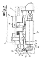
- an electric door opener is shown with Bertd Wegbarer latch 1, wherein such an electric door opener, for example, is attached to the back of a strike plate or on a closing strip in the region of a passage opening of the closing strip.
- the electric door opener has a ⁇ ffnergephaseuse 2 and a pivotally mounted in the ⁇ ffnergephaseuse (spring-loaded) ⁇ ffnerfalle 3 with a locking lug 4, which is engaged behind by the latch in pre-pressed closed position.
- a pivotally mounted (spring-loaded) blocking lever 5 and acting on the blocking lever 5 (spring-loaded) pawl 6 is provided in the ⁇ ffnergephinuse 2 .
- Fig. 3 shows the door opener in the blocking position, in which case the blocking lever 5 with its locking edge 8 or locking lug against a corresponding locking edge 9 or locking nose of the pawl 6 is applied, so that the blocking lever 5 can not be pivoted down and the opener 3 accordingly is blocked against pivoting.
- Fig. 3 shows the door opener in the blocking position, in which case the blocking lever 5 with its locking edge 8 or locking lug against a corresponding locking edge 9 or locking nose of the pawl 6 is applied, so that the blocking lever 5 can not be pivoted down and the opener 3 accordingly is blocked against pivoting.
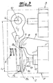
- the effective lever arm is greater by the amount ⁇ L 1 than in the case where the actuating tappet would work directly against the pawl on its actuating axis. It then follows, taking into account the general leverage laws that at a given power or operating force of the solenoid 7, an increased force can be applied to the pawl during the first operating part stroke.
- the actuating plunger 13 acts after the first operating part during a second Betjanssteilhubes at a second point A 2 of the pawl 6, which is spaced to form a shortened lever arm L 2 by a predetermined amount .DELTA.L 2 of the actuating axis, and Although in the direction of the pivot axis 10 of the pawl 6 back.
- this second point is spaced by the amount .DELTA.L 2 of the actuating axis 12, so that is now working with a shortened lever arm L 2 .
- the actuating plunger 13 operates with the interposition of an actuating element 14 on the pawl 6, this actuator 14 is responsible for the offset of the point or the points A 1 , A 2 and consequently for the extension and / or shortening of the lever arm.
- the actuating element 14 in the exemplary embodiments, a first, corresponding to the first point of application A 1 actuating surface B 1 and a second, with the second point of application A 2 corresponding actuating surface B 2 .
- the actuating element 14 is designed as an actuating head 14, which is rigidly connected to the actuating plunger 13. 2 to 4 that the actuating head 14 here (together with the actuating plunger) is T-shaped, wherein the two actuating surfaces B 1 , B 2 are each connected end to the T-bar. It is understood that the configuration of the actuating surfaces B 1 , B 2 and the shape of the pawl 6 are coordinated with each other in order to achieve the desired operating characteristic. It is expedient if - as shown in FIGS. 3 and 4 - the pawl 6 is formed curved overall or profiled or has each other at a predetermined angle employed areas. In this way it is ensured that a perfect power transmission takes place.
- the surfaces of the pawl 6 and the actuating head 14 to match so that a continuous transition between the first actuating stroke and the second actuating stroke, so that, for example, with a (steadily) decreasing lever arm is used.
- the actuating element 14 is designed in each case as an actuating lever 14a, 14b.
- Fig. 5 shows an embodiment in which the actuating lever 14a is pivotally hinged as a rigid lever to the pawl 6 and beyond pivotally supported on the ⁇ ffnergephaseuse 2.
- the pawl 6 acted upon spring 11 is here between the actuating lever 14a on the one hand and pawl 6 on the other hand arranged.
- This configuration makes it possible to work with relatively weak springs and yet to generate high restoring forces. It can be seen in Fig. 5 that at the beginning of the tripping operation of the actuating plunger 13 engages the actuating lever 14a at a first point A 1 with extended lever arm, namely in the region of the pivot point D between the actuating lever 14a and pawl 6.
- Fig. 6 shows a further embodiment of the invention, in which the actuating element is designed as an actuating spring 14b in the embodiment as a leaf spring.
- This actuating spring 14b is also supported on the opener housing 2 or fastened to the opener housing.
- the actuating tappet 13 first works via the leaf spring 14b at a first point of application A 1 on the pawl 6, which provides for an enlarged lever arm.
- the leaf spring strikes in a region closer to the pivot axis A 2 to the pawl, so that you can then work with reduced lever arm.
- Reduced lever means here, reduced with respect to the initially extended lever arm, wherein the reduced lever arm is still greater than or equal to the "conventional" lever arm with lying on the operating axis point.
Landscapes
- Lock And Its Accessories (AREA)
Applications Claiming Priority (1)
| Application Number | Priority Date | Filing Date | Title |
|---|---|---|---|
| DE200610013034 DE102006013034B3 (de) | 2006-03-20 | 2006-03-20 | Elektrischer Türöffner |
Publications (3)
| Publication Number | Publication Date |
|---|---|
| EP1837462A2 true EP1837462A2 (fr) | 2007-09-26 |
| EP1837462A3 EP1837462A3 (fr) | 2008-10-01 |
| EP1837462B1 EP1837462B1 (fr) | 2012-05-16 |
Family
ID=37950186
Family Applications (1)
| Application Number | Title | Priority Date | Filing Date |
|---|---|---|---|
| EP20060026394 Active EP1837462B1 (fr) | 2006-03-20 | 2006-12-20 | Dispositif d'ouverture de porte électrique |
Country Status (2)
| Country | Link |
|---|---|
| EP (1) | EP1837462B1 (fr) |
| DE (1) | DE102006013034B3 (fr) |
Families Citing this family (1)
| Publication number | Priority date | Publication date | Assignee | Title |
|---|---|---|---|---|
| US20240035310A1 (en) * | 2022-07-29 | 2024-02-01 | Omar Chibli | Low-voltage electromechanical strike device |
Citations (1)
| Publication number | Priority date | Publication date | Assignee | Title |
|---|---|---|---|---|
| EP0851077A1 (fr) | 1996-12-30 | 1998-07-01 | NUOVA F.E.B. - Fabbrica Elettroapparecchiature Bologna S.r.l. | Unité de verrouillage |
Family Cites Families (4)
| Publication number | Priority date | Publication date | Assignee | Title |
|---|---|---|---|---|
| DE8611467U1 (de) * | 1986-04-25 | 1986-06-12 | Fritz Fuss Kg, 7470 Albstadt | Elektrischer Türöffner |
| DE19630411C2 (de) * | 1996-07-26 | 1998-10-08 | Fuss Fritz Gmbh & Co | Sperr-/Freigabevorrichtung für eine Schwenkfalle eines Türöffners |
| DE19856624C2 (de) * | 1998-12-08 | 2003-05-15 | Fuss Fritz Gmbh & Co | Elektrischer Türöffner |
| AU2002952629A0 (en) * | 2002-11-13 | 2002-11-28 | Securicom (Nsw) Pty Ltd | Solenoid operated latching strike |
-
2006
- 2006-03-20 DE DE200610013034 patent/DE102006013034B3/de not_active Expired - Lifetime
- 2006-12-20 EP EP20060026394 patent/EP1837462B1/fr active Active
Patent Citations (1)
| Publication number | Priority date | Publication date | Assignee | Title |
|---|---|---|---|---|
| EP0851077A1 (fr) | 1996-12-30 | 1998-07-01 | NUOVA F.E.B. - Fabbrica Elettroapparecchiature Bologna S.r.l. | Unité de verrouillage |
Also Published As
| Publication number | Publication date |
|---|---|
| DE102006013034B3 (de) | 2007-05-10 |
| EP1837462B1 (fr) | 2012-05-16 |
| EP1837462A3 (fr) | 2008-10-01 |
Similar Documents
| Publication | Publication Date | Title |
|---|---|---|
| EP0653010B1 (fr) | Dispositif de blocage des portes d'un vehicule automobile | |
| DE19906997C2 (de) | Kraftfahrzeug-Türschloß, -Haubenschloß oder -Klappenschloß | |
| EP3832055B1 (fr) | Unité de verrouillage pour une installation de verrouillage d'une porte | |
| EP1485558A1 (fr) | Serrure, en particulier pour portes de vehicule, battants ou analogues | |
| EP2673435B1 (fr) | Système de serrure pour bloc-porte à deux vantaux à fonction anti-panique | |
| EP3640419B1 (fr) | Serrure de véhicule automobile pour une porte de véhicule automobile | |
| EP1692356B1 (fr) | Gache electrique | |
| EP4284991A1 (fr) | Verrou de véhicule automobile | |
| EP2987931B1 (fr) | Serrure de véhicule automobile | |
| DE10140385B4 (de) | Servo-Schlosshalter für einen Türverschluss, insbesondere Kraftfahrzeugtürverschluss | |
| DE102011108438A1 (de) | Kraftfahrzeugschloss | |
| WO2024012616A1 (fr) | Serrure de véhicule à moteur, en particulier serrure de portière de véhicule à moteur | |
| DE10360225B3 (de) | Elektrisch betätigbarer Türöffner | |
| EP3628801B1 (fr) | Dispositif de fermeture pour une porte et procédé pour ouvrir une porte | |
| DE202009016137U1 (de) | Treibstangenschloss mit Panikfunktion und Mehrfachverriegelung | |
| AT9709U1 (de) | Türschloss | |
| EP1683936B1 (fr) | Serrure avec pêne demi-tour et entraînement pour le pêne demi-tour | |
| EP1837462B1 (fr) | Dispositif d'ouverture de porte électrique | |
| DE102004034529B3 (de) | Elektromechanisches Türschloss | |
| EP1339932A2 (fr) | Dispositif pour actionner une serrure sur une porte, un cache-serrure ou analogue, notamment d'un vehicule | |
| EP2453086B1 (fr) | Ferrure de crémone pour battant fixe de fenêtres ou de portes à deux vantaux sans montant médian | |
| EP3798393A1 (fr) | Dispositif de commande d'urgence destiné à l'ouverture manuelle d'une porte de véhicule | |
| EP4263984B1 (fr) | Serrure pour véhicule automobile | |
| EP3536882A1 (fr) | Serrure pour un battant | |
| EP1700981A2 (fr) | Dispositif d'ouverture de porte commandé à distance |
Legal Events
| Date | Code | Title | Description |
|---|---|---|---|
| PUAI | Public reference made under article 153(3) epc to a published international application that has entered the european phase |
Free format text: ORIGINAL CODE: 0009012 |
|
| AK | Designated contracting states |
Kind code of ref document: A2 Designated state(s): AT BE BG CH CY CZ DE DK EE ES FI FR GB GR HU IE IS IT LI LT LU LV MC NL PL PT RO SE SI SK TR |
|
| AX | Request for extension of the european patent |
Extension state: AL BA HR MK YU |
|
| PUAL | Search report despatched |
Free format text: ORIGINAL CODE: 0009013 |
|
| AK | Designated contracting states |
Kind code of ref document: A3 Designated state(s): AT BE BG CH CY CZ DE DK EE ES FI FR GB GR HU IE IS IT LI LT LU LV MC NL PL PT RO SE SI SK TR |
|
| AX | Request for extension of the european patent |
Extension state: AL BA HR MK RS |
|
| 17P | Request for examination filed |
Effective date: 20081202 |
|
| AKX | Designation fees paid |
Designated state(s): AT BE BG CH CY CZ DE DK EE ES FI FR GB GR HU IE IS IT LI LT LU LV MC NL PL PT RO SE SI SK TR |
|
| 17Q | First examination report despatched |
Effective date: 20090716 |
|
| GRAP | Despatch of communication of intention to grant a patent |
Free format text: ORIGINAL CODE: EPIDOSNIGR1 |
|
| GRAS | Grant fee paid |
Free format text: ORIGINAL CODE: EPIDOSNIGR3 |
|
| GRAA | (expected) grant |
Free format text: ORIGINAL CODE: 0009210 |
|
| AK | Designated contracting states |
Kind code of ref document: B1 Designated state(s): AT BE BG CH CY CZ DE DK EE ES FI FR GB GR HU IE IS IT LI LT LU LV MC NL PL PT RO SE SI SK TR |
|
| REG | Reference to a national code |
Ref country code: GB Ref legal event code: FG4D Free format text: NOT ENGLISH |
|
| REG | Reference to a national code |
Ref country code: CH Ref legal event code: EP |
|
| REG | Reference to a national code |
Ref country code: AT Ref legal event code: REF Ref document number: 558185 Country of ref document: AT Kind code of ref document: T Effective date: 20120615 |
|
| REG | Reference to a national code |
Ref country code: IE Ref legal event code: FG4D Free format text: LANGUAGE OF EP DOCUMENT: GERMAN |
|
| REG | Reference to a national code |
Ref country code: DE Ref legal event code: R096 Ref document number: 502006011434 Country of ref document: DE Effective date: 20120712 |
|
| REG | Reference to a national code |
Ref country code: NL Ref legal event code: T3 |
|
| REG | Reference to a national code |
Ref country code: LT Ref legal event code: MG4D Effective date: 20120516 |
|
| PG25 | Lapsed in a contracting state [announced via postgrant information from national office to epo] |
Ref country code: PL Free format text: LAPSE BECAUSE OF FAILURE TO SUBMIT A TRANSLATION OF THE DESCRIPTION OR TO PAY THE FEE WITHIN THE PRESCRIBED TIME-LIMIT Effective date: 20120516 Ref country code: CY Free format text: LAPSE BECAUSE OF FAILURE TO SUBMIT A TRANSLATION OF THE DESCRIPTION OR TO PAY THE FEE WITHIN THE PRESCRIBED TIME-LIMIT Effective date: 20120516 Ref country code: FI Free format text: LAPSE BECAUSE OF FAILURE TO SUBMIT A TRANSLATION OF THE DESCRIPTION OR TO PAY THE FEE WITHIN THE PRESCRIBED TIME-LIMIT Effective date: 20120516 Ref country code: LT Free format text: LAPSE BECAUSE OF FAILURE TO SUBMIT A TRANSLATION OF THE DESCRIPTION OR TO PAY THE FEE WITHIN THE PRESCRIBED TIME-LIMIT Effective date: 20120516 Ref country code: SE Free format text: LAPSE BECAUSE OF FAILURE TO SUBMIT A TRANSLATION OF THE DESCRIPTION OR TO PAY THE FEE WITHIN THE PRESCRIBED TIME-LIMIT Effective date: 20120516 Ref country code: IS Free format text: LAPSE BECAUSE OF FAILURE TO SUBMIT A TRANSLATION OF THE DESCRIPTION OR TO PAY THE FEE WITHIN THE PRESCRIBED TIME-LIMIT Effective date: 20120916 |
|
| PG25 | Lapsed in a contracting state [announced via postgrant information from national office to epo] |
Ref country code: GR Free format text: LAPSE BECAUSE OF FAILURE TO SUBMIT A TRANSLATION OF THE DESCRIPTION OR TO PAY THE FEE WITHIN THE PRESCRIBED TIME-LIMIT Effective date: 20120817 Ref country code: SI Free format text: LAPSE BECAUSE OF FAILURE TO SUBMIT A TRANSLATION OF THE DESCRIPTION OR TO PAY THE FEE WITHIN THE PRESCRIBED TIME-LIMIT Effective date: 20120516 Ref country code: PT Free format text: LAPSE BECAUSE OF FAILURE TO SUBMIT A TRANSLATION OF THE DESCRIPTION OR TO PAY THE FEE WITHIN THE PRESCRIBED TIME-LIMIT Effective date: 20120917 Ref country code: LV Free format text: LAPSE BECAUSE OF FAILURE TO SUBMIT A TRANSLATION OF THE DESCRIPTION OR TO PAY THE FEE WITHIN THE PRESCRIBED TIME-LIMIT Effective date: 20120516 |
|
| PG25 | Lapsed in a contracting state [announced via postgrant information from national office to epo] |
Ref country code: CZ Free format text: LAPSE BECAUSE OF FAILURE TO SUBMIT A TRANSLATION OF THE DESCRIPTION OR TO PAY THE FEE WITHIN THE PRESCRIBED TIME-LIMIT Effective date: 20120516 Ref country code: RO Free format text: LAPSE BECAUSE OF FAILURE TO SUBMIT A TRANSLATION OF THE DESCRIPTION OR TO PAY THE FEE WITHIN THE PRESCRIBED TIME-LIMIT Effective date: 20120516 Ref country code: DK Free format text: LAPSE BECAUSE OF FAILURE TO SUBMIT A TRANSLATION OF THE DESCRIPTION OR TO PAY THE FEE WITHIN THE PRESCRIBED TIME-LIMIT Effective date: 20120516 Ref country code: SK Free format text: LAPSE BECAUSE OF FAILURE TO SUBMIT A TRANSLATION OF THE DESCRIPTION OR TO PAY THE FEE WITHIN THE PRESCRIBED TIME-LIMIT Effective date: 20120516 Ref country code: EE Free format text: LAPSE BECAUSE OF FAILURE TO SUBMIT A TRANSLATION OF THE DESCRIPTION OR TO PAY THE FEE WITHIN THE PRESCRIBED TIME-LIMIT Effective date: 20120516 |
|
| PG25 | Lapsed in a contracting state [announced via postgrant information from national office to epo] |
Ref country code: IT Free format text: LAPSE BECAUSE OF FAILURE TO SUBMIT A TRANSLATION OF THE DESCRIPTION OR TO PAY THE FEE WITHIN THE PRESCRIBED TIME-LIMIT Effective date: 20120516 |
|
| PLBE | No opposition filed within time limit |
Free format text: ORIGINAL CODE: 0009261 |
|
| STAA | Information on the status of an ep patent application or granted ep patent |
Free format text: STATUS: NO OPPOSITION FILED WITHIN TIME LIMIT |
|
| 26N | No opposition filed |
Effective date: 20130219 |
|
| PG25 | Lapsed in a contracting state [announced via postgrant information from national office to epo] |
Ref country code: ES Free format text: LAPSE BECAUSE OF FAILURE TO SUBMIT A TRANSLATION OF THE DESCRIPTION OR TO PAY THE FEE WITHIN THE PRESCRIBED TIME-LIMIT Effective date: 20120827 |
|
| REG | Reference to a national code |
Ref country code: DE Ref legal event code: R097 Ref document number: 502006011434 Country of ref document: DE Effective date: 20130219 |
|
| BERE | Be: lapsed |
Owner name: CARL FUHR G.M.B.H. & CO. KG Effective date: 20121231 |
|
| PG25 | Lapsed in a contracting state [announced via postgrant information from national office to epo] |
Ref country code: MC Free format text: LAPSE BECAUSE OF NON-PAYMENT OF DUE FEES Effective date: 20121231 Ref country code: BG Free format text: LAPSE BECAUSE OF FAILURE TO SUBMIT A TRANSLATION OF THE DESCRIPTION OR TO PAY THE FEE WITHIN THE PRESCRIBED TIME-LIMIT Effective date: 20120816 |
|
| REG | Reference to a national code |
Ref country code: CH Ref legal event code: PL |
|
| REG | Reference to a national code |
Ref country code: IE Ref legal event code: MM4A |
|
| PG25 | Lapsed in a contracting state [announced via postgrant information from national office to epo] |
Ref country code: BE Free format text: LAPSE BECAUSE OF NON-PAYMENT OF DUE FEES Effective date: 20121231 |
|
| PG25 | Lapsed in a contracting state [announced via postgrant information from national office to epo] |
Ref country code: CH Free format text: LAPSE BECAUSE OF NON-PAYMENT OF DUE FEES Effective date: 20121231 Ref country code: LI Free format text: LAPSE BECAUSE OF NON-PAYMENT OF DUE FEES Effective date: 20121231 Ref country code: IE Free format text: LAPSE BECAUSE OF NON-PAYMENT OF DUE FEES Effective date: 20121220 |
|
| PG25 | Lapsed in a contracting state [announced via postgrant information from national office to epo] |
Ref country code: TR Free format text: LAPSE BECAUSE OF FAILURE TO SUBMIT A TRANSLATION OF THE DESCRIPTION OR TO PAY THE FEE WITHIN THE PRESCRIBED TIME-LIMIT Effective date: 20120516 |
|
| PG25 | Lapsed in a contracting state [announced via postgrant information from national office to epo] |
Ref country code: LU Free format text: LAPSE BECAUSE OF NON-PAYMENT OF DUE FEES Effective date: 20121220 |
|
| PG25 | Lapsed in a contracting state [announced via postgrant information from national office to epo] |
Ref country code: HU Free format text: LAPSE BECAUSE OF FAILURE TO SUBMIT A TRANSLATION OF THE DESCRIPTION OR TO PAY THE FEE WITHIN THE PRESCRIBED TIME-LIMIT Effective date: 20061220 |
|
| REG | Reference to a national code |
Ref country code: FR Ref legal event code: PLFP Year of fee payment: 10 |
|
| REG | Reference to a national code |
Ref country code: FR Ref legal event code: PLFP Year of fee payment: 11 |
|
| REG | Reference to a national code |
Ref country code: FR Ref legal event code: PLFP Year of fee payment: 12 |
|
| PGFP | Annual fee paid to national office [announced via postgrant information from national office to epo] |
Ref country code: GB Payment date: 20251219 Year of fee payment: 20 |
|
| PGFP | Annual fee paid to national office [announced via postgrant information from national office to epo] |
Ref country code: AT Payment date: 20251222 Year of fee payment: 20 |
|
| PGFP | Annual fee paid to national office [announced via postgrant information from national office to epo] |
Ref country code: NL Payment date: 20251219 Year of fee payment: 20 Ref country code: FR Payment date: 20251222 Year of fee payment: 20 |
|
| PGFP | Annual fee paid to national office [announced via postgrant information from national office to epo] |
Ref country code: DE Payment date: 20251218 Year of fee payment: 20 |