EP1837477B1 - Fenster oder Tür mit Lüftung - Google Patents
Fenster oder Tür mit Lüftung Download PDFInfo
- Publication number
- EP1837477B1 EP1837477B1 EP07005787A EP07005787A EP1837477B1 EP 1837477 B1 EP1837477 B1 EP 1837477B1 EP 07005787 A EP07005787 A EP 07005787A EP 07005787 A EP07005787 A EP 07005787A EP 1837477 B1 EP1837477 B1 EP 1837477B1
- Authority
- EP
- European Patent Office
- Prior art keywords
- ventilation
- flaps
- window according
- profiles
- profile
- Prior art date
- Legal status (The legal status is an assumption and is not a legal conclusion. Google has not performed a legal analysis and makes no representation as to the accuracy of the status listed.)
- Not-in-force
Links
- 238000009423 ventilation Methods 0.000 title claims abstract description 104
- 230000000903 blocking effect Effects 0.000 claims abstract 2
- 241000255925 Diptera Species 0.000 claims description 11
- 241000238631 Hexapoda Species 0.000 claims description 5
- 229920003023 plastic Polymers 0.000 claims description 4
- 239000004033 plastic Substances 0.000 claims description 4
- 238000013016 damping Methods 0.000 claims description 2
- 239000000463 material Substances 0.000 claims description 2
- 230000002093 peripheral effect Effects 0.000 claims 2
- 238000010276 construction Methods 0.000 claims 1
- 238000004519 manufacturing process Methods 0.000 description 8
- 230000008901 benefit Effects 0.000 description 4
- 230000004313 glare Effects 0.000 description 4
- 238000000465 moulding Methods 0.000 description 2
- 230000004044 response Effects 0.000 description 2
- 239000000853 adhesive Substances 0.000 description 1
- 230000001070 adhesive effect Effects 0.000 description 1
- 230000002457 bidirectional effect Effects 0.000 description 1
- 230000006735 deficit Effects 0.000 description 1
- 230000000694 effects Effects 0.000 description 1
- 230000006872 improvement Effects 0.000 description 1
- 238000009434 installation Methods 0.000 description 1
- 230000009545 invasion Effects 0.000 description 1
- 238000000034 method Methods 0.000 description 1
- 230000008569 process Effects 0.000 description 1
- 230000009467 reduction Effects 0.000 description 1
- 230000007704 transition Effects 0.000 description 1
Images


Classifications
-
- E—FIXED CONSTRUCTIONS
- E06—DOORS, WINDOWS, SHUTTERS, OR ROLLER BLINDS IN GENERAL; LADDERS
- E06B—FIXED OR MOVABLE CLOSURES FOR OPENINGS IN BUILDINGS, VEHICLES, FENCES OR LIKE ENCLOSURES IN GENERAL, e.g. DOORS, WINDOWS, BLINDS, GATES
- E06B7/00—Special arrangements or measures in connection with doors or windows
- E06B7/02—Special arrangements or measures in connection with doors or windows for providing ventilation, e.g. through double windows; Arrangement of ventilation roses
- E06B7/10—Special arrangements or measures in connection with doors or windows for providing ventilation, e.g. through double windows; Arrangement of ventilation roses by special construction of the frame members
-
- F—MECHANICAL ENGINEERING; LIGHTING; HEATING; WEAPONS; BLASTING
- F24—HEATING; RANGES; VENTILATING
- F24F—AIR-CONDITIONING; AIR-HUMIDIFICATION; VENTILATION; USE OF AIR CURRENTS FOR SCREENING
- F24F13/00—Details common to, or for air-conditioning, air-humidification, ventilation or use of air currents for screening
- F24F13/08—Air-flow control members, e.g. louvres, grilles, flaps or guide plates
- F24F13/18—Air-flow control members, e.g. louvres, grilles, flaps or guide plates specially adapted for insertion in flat panels, e.g. in door or window-pane
Definitions
- the invention relates to a window or a door with an openable sash and a frame, wherein at least one of a multi-chambered hollow profile, in particular made of plastic and having ventilation openings for the passage of air, and wherein in a hollow chamber of the frame ventilation openings with movable flaps for throttling or shut off the air flow are provided, wherein the flaps are pivotally mounted in separate ventilation profiles and the ventilation profiles have internal stops for the flaps in the closed position, and wherein the ventilation profiles have inlet and outlet openings.
- Windows or doors consisting of a sash and a frame, wherein at least the frame consists of a multi-chambered hollow profile, in particular made of plastic, are for example from the EP 0 719 374 B1 known.
- the frame is designed so that air from the outside of the window can enter through different chambers of the hollow profile in the frame, from there can flow through a forming with the window closed gap between the glare and sash and ultimately on the inside of the window more precisely Openings on the upper cross member of the sash can escape into the interior.
- a generic object is from the EP 1 500 773 A1 known.
- the cited document discloses an air flow limiting device for windows, which is fastened with latching means in the receiving groove of a frame profile and cooperates with corresponding ventilation openings. Again, flying insects, such as mosquitoes, flies or the like can penetrate into the ventilation system and affect its function.
- the object of the present invention is therefore to improve the ventilation system so that it works more reliable than before, pollution by mosquitoes, etc. is prevented and that even in strong wind or gusts of air optimum air flow from the window or door outside to Window or door inside is guaranteed.
- At least one opening in the form of a series of such small holes is designed so that mosquitoes, flies and similar sized insects can not penetrate into the ventilation profile.
- the arrangement of the flaps in separate ventilation profiles independent of the Blend- or casement arrangement of the flaps is possible.
- the ventilation profiles can be used after the production of the sash or wing frame in this and the production of the window or the door as a whole is considerably simplified and accelerated.
- the flaps are pivotally mounted in the ventilation profiles and have internal stops for the flaps in the closed position. This makes it possible that the flaps no longer correspond with external ventilation openings of the frame, but with the openings of their ventilation profile, whereby the closing process is more precise.
- the response of the flap in strong winds or gusts can be optimized.
- At least one opening in the form of a series of such small holes is designed so that mosquitoes, flies and insects of comparable size can not penetrate into the ventilation profile.
- the flaps can be easily mounted in the ventilation profile.
- the ventilation profile can initially be made separately as the flaps, so that the production of the flaps or the ventilation profile can be relatively easily done. The installation of the flaps in the ventilation profile is then as easy as fast on the locking connection.
- the flaps are acted upon on both sides in its open position by the incoming air.
- the advantage of this type of flow is that at low air flow, the flap does not immediately go into the closed position, whereas at higher flow, the flap is at least partially pivoted and finally pushed completely against the stop at even stronger flow. For a steady control of the amount of air flowing through it is possible.
- the ventilation profiles have at least two successive flaps in the longitudinal direction.
- an improvement of the response of the flaps for the regulation of the air flow is achieved by the ventilation profile.
- the air can penetrate in an optimal manner from the ventilation profile in the hollow section and can flow out again, it is essential that the ventilation profile corresponds to at least one slot of the hollow chamber. This provides a direct flow connection between the ventilation profile and the hollow chamber.
- the ventilation profiles are fastened by clipping on the glare and / or sash, in particular in the slot. This allows a very simple mounting of the ventilation profile on the frame without additional fasteners such as screws or adhesives. If this is also attached in the slot, no further recesses are required for receiving the clip connection, but the existing slots for the passage of air can also take up all or part of the clip connection of the ventilation profile.
- the ventilation profiles are formed in two pieces and connected to each other by means of a circumferential weld.
- the two-piece design of the ventilation profiles is used to simplify the production of such Ventilation profiles, the one-piece design would be very expensive due to the undercuts in the cross section of the ventilation profile.
- the circumferential weld extends in the region of the pivotal mounting of the flaps in the ventilation profile and substantially along its longitudinal axis.
- the weld is a simple production of the two moldings in the foreground. Both moldings consist of only one flank of a U-shaped profile, wherein at least one flank also has end-side end walls.
- the weld is arranged in the region of the pivotal mounting of the flaps, so that both mold parts each contain a part of the recess for the latching connection.
- the air flowing through is not completely shut off in strong gusts, it is essential that the flaps of the ventilation profiles with positive support on the attacks do not cause a total seal. This is achieved by leaving a certain gap to the ventilation profile along the pivot axis of the flap.
- the flaps of the ventilation profiles from an approximately vertical position by up to about 70 °, suitably only up to 60 ° pivotable. This allows a smooth low-noise transition between the open and the closed position of the flap.
- the attachment of the ventilation profiles is best done at the ends of the longitudinal axis of the ventilation profiles.
- the advantage here is that the attachment points are kept to a minimum and as much space for the flowing through Air is provided so that ultimately the air as evenly as possible through the ventilation profile.
- a seal is arranged between the glare and casement, which has a plurality of recesses and which controls the supplied air depending on the version. As a result, not only a regulation of the flow rate of the air is achieved, but the flow behavior of the air is also optimized in strong winds.
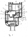
- FIG. 1 shows a window with an openable sash 1 and a frame 2.
- Both the sash 1 and the frame 2 consist of a multi-chambered hollow section 3 and 3 '. This is in particular made of plastic.
- ventilation openings 4, 4', 4 "and 4 '" for the passage of air from outside to inside.
- a ventilation profile 5 is arranged on the frame 2. It is mounted via a clip connection 11 in a hollow chamber 5 '.
- the ventilation profile 5 has a substantially U-shaped cross section and sits in the air flow between the outer opening 4 "'and the inner opening 4.
- the ventilation profile 5 numerous inlet openings 9 at the bottom and outlet openings 10 at the top.
- the inlet openings 9 are designed as rows of holes.
- a seal 13 which has a plurality of recesses and which regulates the incoming air depending on the requirements and the remaining air gap, is arranged between the glare and the sash frame at the ventilation opening 4 '' '.
- the seal is clipped into the window frame 2.
- the ventilation profile 5 is mounted as far as possible from the inner opening 4 or the inner side of the casement 1. This not only provides effective noise reduction, but also protection the inner frame chambers against pollution.
- the flap 7 is held by its own weight in the open position, that is, substantially in the vertical position and lies with its free end against a stop 8 'for the open position.
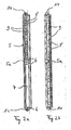
- FIG. 2 shows the ventilation profile 5 seen from the top left, seen from the bottom right. It can be seen that the ventilation profile is divided by a gutter 5a into two compartments, in each of which a flap 7 is pivotally mounted. In the lower part of FIG. 2a the flap '7 is in the closed position, in the upper part in the open position, so that you can see there the air inlet openings 9 and 9'.
- FIG. 4 is a terminal plan view in the longitudinal direction of the ventilation profile 5 can be seen.
- On the underside of the ventilation profile 5 extend in the longitudinal direction of the inlet openings 9 and 9 '. The air flows through these two openings 9, 9 'on both sides of the in FIG. 3 shown flap 7.
- the ventilation profile consists of two halves, which are connected by a circumferential weld joint 12.
- the weld runs in the region of the pivot bearing 6 of the flap and further along the longitudinal axis of the ventilation profile. 5
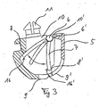
- FIG. 3 is a ventilation profile 5 according to the invention in a cross section with the operation of the flap 7 to see.
- FIG. 3 to see the flap 7 in its open position 16 'on the stop 8' and in its closed position 16 on the stop 8.
- the open position 16 'of the flap 7 the air flowing through the ventilation profile leaves through the upper opening 10, the ventilation profile, whereas in the closed position 16, the air is not completely blocked, as by means of a spacing of the pivot bearing 6 from the edge of the ventilation profile 5, a gap 10' remains free over which the air can leave the ventilation profile 5.
- a defined flow of air from the inlet opening 4 '"to the inner opening 4 is ensured even in strong wind.
- FIG. 5 is a section of a window frame to see on which a ventilation profile 5 is to be arranged.
- the frame in this case has elongated slots 17 in the longitudinal direction, in which the ventilation profile via the clip connection 11 can be clipped.
- the frame 2 may also have additional round openings 18 into which the ventilation profile can be clipped with the clip connection or can be screwed by means of the blind holes 15.
- the ventilation profile is installed in each case in a hollow chamber accessible from the outside of the window frame 2. It is of course within the scope of the invention to arrange it instead in the space between the frame and sash or on the sash itself.
- the invention offers the advantage that even with very strong wind conditions, a defined flow of air through from the outside to the inside of a window or a door is made possible.
- the present invention also provides protection against invasion of insects.
Landscapes
- Engineering & Computer Science (AREA)
- Civil Engineering (AREA)
- Structural Engineering (AREA)
- Chemical & Material Sciences (AREA)
- Combustion & Propulsion (AREA)
- Mechanical Engineering (AREA)
- General Engineering & Computer Science (AREA)
- Specific Sealing Or Ventilating Devices For Doors And Windows (AREA)
Description
- Die Erfindung betrifft ein Fenster oder eine Tür mit einem zu öffnenden Flügelrahmen und einem Blendrahmen, wobei zumindest einer aus einem mehrkammerigen Hohlprofil, insbesondere aus Kunststoff besteht und Lüftungsöffnungen zur Durchleitung von Luft aufweist, und wobei in einer Hohlkammer des Rahmens Lüftungsöffnungen mit beweglichen Klappen zum Drosseln oder Absperren der Luftströmung vorgesehen sind, wobei die Klappen in separaten Lüftungsprofilen schwenkbar gelagert sind und die Lüftungsprofile interne Anschläge für die Klappen in der Geschlossenstellung aufweisen, und wobei die Lüftungsprofile Ein- und Ausströmöffnungen aufweisen.
- Fenster oder Türen bestehend aus einem Flügelrahmen und einem Blendrahmen, wobei zumindest der Blendrahmen aus einem mehrkammerigen Hohlprofil, insbesondere aus Kunststoff besteht, sind beispielsweise aus der
EP 0 719 374 B1 bekannt. Der Blendrahmen ist so ausgestaltet, dass Luft von der Außenseite des Fensters über verschiedene Kammern des Hohlprofils in den Blendrahmen eintreten kann, von dort durch einen sich bei geschlossenem Fenster bildenden Zwischenraum zwischen Blend- und Flügelrahmen hindurchströmen kann und letztendlich auf der Innenseite des Fensters genauer über Öffnungen am oberen Querholm des Flügelrahmens in den Innenraum austreten kann. - Bei starkem Wind ist es außerdem bekannt, die Luftströmung durch die verschiedenen Kammern mittels einer im Blend- oder Flügelrahmen angebrachten Klappe zu regulieren, das heißt, bei starkem Wind wird die Klappe gegen eine Öffnung zwischen zwei Hohlkammern gedrückt, so dass keine Luft mehr von außen durchströmen kann. Wird der Wind schwächer, öffnet sich die Klappe wieder automatisch, so dass wiederum die gewünschte Zwangslüftung erfolgt.
- Bei diesen bekannten Lüftungen durch das Fenster hindurch kann es, insbesondere in Regionen, in denen häufig Böen und/oder starke Winde auftreten, zu einem kompletten Verschließen der Klappe über längere Zeiträume, meist mehrere Stunden kommen. Dies führt zu einer deutlichen Beeinträchtigung der Zwangslüftung. Die Gefahr hierbei ist, dass Schimmelbildung im Raum, der zur Innenseite des Fensters korrespondiert, begünstigt wird.
- Weiterhin hat sich als nachteilig bei derartigen Anordnungen erwiesen, dass Mücken, Fliegen, etc. in die Lüftungsöffnungen eindringen können und dabei die Funktion der Lüftungsklappe stören. Bei starken Winden verschließt die Klappe dann nicht mehr und verharrt in ihrer Offenstellung, was dazu führt, dass ständig die maximale Luftmenge einströmt und so den Raum mehr als nötig belüftet.
- Nicht zuletzt ist die Herstellung derartiger Klappen direkt am Rahmen sehr kompliziert und aufwendig und in der Folge daher kostenintensiv.
- Ein gattungsgemäßer Gegenstand ist aus der
EP 1 500 773 A1 bekannt. Die genannte Druckschrift offenbart eine Luftstrombegrenzungs-Vorrichtung für Fenster, welche mit Rastmitteln in der Aufnahmenut eines Blendrahmenprofils befestigt ist und mit entsprechenden Lüftungsöffnungen zusammenwirkt. Auch hier können Fluginsekten, wie Mücken, Fliegen oder dergleichen in das Lüftungssystem eindringen und dessen Funktion beeinträchtigen. - Die Aufgabe der vorliegenden Erfindung ist es daher, das Lüftungssystem derart zu verbessern, dass es zuverlässiger als bisher funktioniert, ein Verschmutzen durch Mücken, etc. verhindert wird und dass auch bei starkem Wind oder Windböen ein optimaler Luftdurchfluss von der Fenster- bzw. Türaußenseite zur Fenster- bzw. Türinnenseite gewährleistet wird.
- Diese Aufgabe wird erfindungsgemäß dadurch gelöst, dass zumindest eine Öffnung in Form einer Reihe derart kleiner Löcher ausgestaltet ist, dass Mücken, Fliegen und vergleichbar große Insekten nicht in das Lüftungsprofil eindringen können.
- Durch die Anordnung der Klappen in separaten Lüftungsprofilen ist eine vom Blend- bzw. Flügelrahmen unabhängige Anordnung der Klappen möglich. Die Lüftungsprofile können nach der Herstellung des Blend- bzw. Flügelrahmens in diesen eingesetzt werden und die Herstellung des Fensters oder der Tür insgesamt wird merklich vereinfacht und beschleunigt. Um den Durchstrom an Luft zu regeln, sind die Klappen in den Lüftungsprofilen schwenkbar gelagert und besitzen interne Anschläge für die Klappen in der Geschlossenstellung. Dadurch ist es möglich, dass die Klappen nicht mehr mit externen Lüftungsöffnungen des Rahmens korrespondieren, sondern mit den Öffnungen ihres Lüftungsprofiles, wodurch der Schließvorgang präziser wird. Zudem kann durch die örtliche Wahl des Anschlags das Ansprechverhalten der Klappe bei starken Winden oder Böen optimiert werden.
- Damit die Funktion der Klappe auch über längere Zeiträume gewährleistet ist, ist erfindungsgemäß zumindest eine Öffnung in Form einer Reihe derart kleiner Löcher ausgestaltet, dass Mücken, Fliegen und vergleichbar große Insekten nicht in das Lüftungsprofil eindringen können.
- Für die Schwenklagerung der Klappen im Lüftungsprofil ist es vorteilhaft, wenn diese durch eine Rastverbindung realisiert ist. Dadurch können die Klappen einfach im Lüftungsprofil montiert werden. Außerdem kann auf diese Weise das Lüftungsprofil zunächst separat wie die Klappen hergestellt werden, so dass die Produktion der Klappen bzw. des Lüftungsprofils relativ einfach erfolgen kann. Die Montage der Klappen im Lüftungsprofil erfolgt dann ebenso einfach wie schnell über die Rastverbindung.
- Damit die Klappen der Lüftungsprofile bei keiner oder schwacher Luftströmung in ihrer Offenstellung gehalten werden, ist es besonders vorteilhaft, wenn dies durch ihre eigene Gewichtskraft erfolgt. Dadurch werden keine zusätzlichen Bauelemente, wie Motoren, etc. benötigt und diese Art der Anordnung ist sehr kostengünstig, ohne dass die Funktionsweise der Klappe insgesamt dadurch eingeschränkt wird.
- Weiterhin ist es wesentlich, dass die Klappen in ihrer Offenstellung von der einströmenden Luft beidseitig beaufschlagt werden. Der Vorteil dieser Art der Anströmung ist, dass bei schwacher Luftströmung die Klappe nicht sofort in die Geschlossenstellung übergeht, wohingegen bei stärker werdender Strömung die Klappe zumindest teilweise verschwenkt und bei noch stärker werdender Strömung schließlich vollständig gegen den Anschlag gedrückt wird. Damit ist eine stetige Regelung der durchströmenden Luftmenge möglich.
- Zweckmäßigerweise verschwenken die Klappen der Lüftungsprofile bei starker Luftströmung aufgrund des Sogs der durchströmenden Luft ganz oder teilweise in ihre Geschlossenstellung, Diese Art der Anordnung der Klappen ermöglicht eine selbsttätige und damit einfache und kostengünstige Regulierung des Luftstromes durch das Lüftungsprofil.
- Vorteilhafterweise weisen die Lüftungsprofile zumindest zwei in Längsrichtung aufeinander folgende Klappen auf. Durch diese Anordnung der Klappen wird eine Verbesserung des Ansprechverhaltens der Klappen für die Regulierung des Luftstromes durch das Lüftungsprofil erreicht.
- Damit die Luft in optimaler Weise vom Lüftungsprofil in das Hohlprofil eindringen und wieder ausströmen kann, ist es wesentlich, dass das Lüftungsprofil mit zumindest einem Schlitz der Hohlkammer korrespondiert. Dadurch ist eine direkte Strömungsverbindung zwischen Lüftungsprofil und Hohlkammer gegeben.
- Um das Lüftungsprofil zu befestigen, ist es besonders vorteilhaft, dass es an dem genannten Schlitz mit dem Rahmen verbunden wird. Zusätzliche Ausfräsungen oder Bohrlöcher, die den Herstellungsaufwand des Fensterrahmens erhöhen und gleichzeitig die Stabilität des Hohlprofils herabsetzen, können damit vermieden werden.
- Besonders günstig ist es dabei, wenn die Lüftungsprofile durch ein Verklipsen am Blend- und/oder Flügelrahmen, insbesondere in dem Schlitz, befestigt sind. Damit wird eine sehr einfache Montage des Lüftungsprofils am Rahmen ohne zusätzliche Befestigungselemente wie beispielsweise Schrauben oder Klebstoffe ermöglicht. Wird dieses zudem in dem Schlitz befestigt, sind auch für die Aufnahme der Clipverbindung keine weiteren Aussparungen nötig, sondern die bereits bestehenden Schlitze für die Durchführung von Luft können ebenso ganz oder teilweise die Clipverbindung des Lüftungsprofils aufnehmen.
- Zweckmäßigerweise sind die Lüftungsprofile zweistückig ausgebildet und mittels einer umlaufenden Schweißnaht miteinander verbunden. Die zweistückige Ausbildung der Lüftungsprofile dient zur einfacheren Herstellung eines solchen Lüftungsprofils, die einstückige Ausführung wäre aufgrund der Hinterschneidungen im Querschnitt des Lüftungsprofils sehr aufwendig.
- Vorzugsweise verläuft die umlaufende Schweißnaht im Bereich der Schwenklagerung der Klappen im Lüftungsprofil und im Wesentlichen entlang deren Längsachse. Auch bei dieser Anordnung der Schweißnaht steht eine einfache Herstellung der beiden Formteile im Vordergrund. Beide Formteile bestehen aus nur jeweils einer Flanke eines U-förmigen Profils, wobei zumindest eine Flanke auch stirnseitige Abschlusswände aufweist. Für einen einfachen Herstellurigsprozess ist die Schweißnaht im Bereich der Schwenklagerung der Klappen angeordnet, so dass beide Formteile jeweils einen Teil der Aussparung für die Rastverbindung beinhalten.
- Um die Lärmbelästigung durch ein mögliches Zuschlagen der Klappen bei böigem Wind zu vermeiden, ist es vorteilhaft, wenn geeignete Maßnahmen zur Aufpralldämpfung getroffen werden, beispielsweise wenn die Anschläge für die Klappen des Lüftungsprofils und/oder die Klappen ein Dämpfungselement aufweisen oder aus einem Material bestehen, das den Aufprall der Klappen auf die Anschläge dämpft.
- Damit die durchströmende Luft bei starken Böen nicht ganz abgesperrt wird, ist es wesentlich, dass die Klappen der Lüftungsprofile bei formschlüssiger Auflage auf den Anschlägen keine totale Abdichtung bewirken. Dies wird dadurch erreicht, dass entlang der Schwenkachse der Klappe ein gewisser Spalt zum Lüftungsprofil freibleibt.
- Zweckmäßigerweise sind die Klappen der Lüftungsprofile aus einer etwa vertikalen Stellung um bis zu etwa 70°, zweckmäßig nur bis maximal 60° verschwenkbar. Dies ermöglicht einen sanften geräuscharmen Übergang zwischen der Offen- und der Geschlossenstellung der Klappe.
- Die Befestigung der Lüftungsprofile erfolgt am besten an den Enden der Längsachse der Lüftungsprofile. Vorteil hierbei ist, dass die Befestigungspunkte auf ein Minimum beschränkt werden und möglichst viel Raum für die durchströmende Luft zur Verfügung gestellt wird, so dass letztendlich die Luft möglichst gleichmäßig das Lüftungsprofil durchströmen kann.
- Besonders vorteilhaft ist, wenn zwischen Blend- und Flügelrahmen eine Dichtung angeordnet ist, die eine Mehrzahl von Aussparungen aufweist und die je nach Ausführung die zugeführte Luft regelt. Hierdurch wird bereits nicht nur eine Regelung der Durchflussmenge der Luft erreicht, sondern das Strömungsverhalten der Luft wird bei starkem Wind ebenfalls optimiert.
- Weitere Merkmale und Vorteile der Erfindung ergeben sich aus der nachfolgenden Beschreibung eines Ausführungsbeispiels anhand der Zeichnungen und aus den Zeichnungen selbst; dabei zeigt
- Figur 1
- einen Schnitt durch die oberen Profile von Flügel- und Blendrahmen;
- Figur 2
- Draufsichten auf das das Lüftungsprofil von unten und oben:
- Figur 3
- einen Querschnitt durch das Lüftungsprofil mit Wirkungsweise der Klappe;
- Figur 4
- eine Stirnansicht des Lüfturigsprofils;
- Figur 5
- eine dreidimensionale perspektivische Ansicht eines Rahmens mit Lüftungsschlitzen,
-
Figur 1 zeigt ein Fenster mit einem zu öffnenden Flügelrahmen 1 und einem Blendrahmen 2. Sowohl der Flügelrahmen 1 als auch der Blendrahmen 2 bestehen dabei aus einem mehrkammerigen Hohlprofil 3 bzw. 3'. Dieses ist insbesondere aus Kunststoff hergestellt. In dem Hohlprofil 3 bzw. 3' sind Lüftungsöffnungen 4, 4', 4" und 4'" zur Durchleitung von Luft von außen nach innen. - Wesentlich ist nun, dass ein Lüftungsprofil 5 am Blendrahmen 2 angeordnet ist. Es ist über eine Clipverbindung 11 in einer Hohlkammer 5' montiert. Das Lüftungsprofil 5 hat im Wesentlichen einen U-förmigen Querschnitt und sitzt im Luftstrom zwischen der Außenöffnung 4"' und der Innenöffnung 4. Für die Regelung der aus der Außenöffnung 4'" in den Zwischenraum zwischen Blendrahmen 2 und Flügelrahmen 1 eintretenden Luft und zur Weiterleitung über die Öffnungen 4", 4' und letztendlich 4 weist das Lüftungsprofil 5 zahlreiche Eintrittsöffnungen 9 an der Unterseite und Austrittsöffnungen 10 an der Oberseite auf. Die Eintrittsöffnungen 9 sind dabei als Lochreihen ausgestaltet.
- Am oberen Rand des Lüftungsprofils 5 sind stirnseitig Ausnehmungen angeordnet, in denen Schwenkzapfen einer Klappe 7 verrastbar sind, so dass die mit den Bezugszeichen 6 markierte Schwenklagerung entsteht. Diese Klappe wird über die Lochreihen 9, 9' beidseitig von Luft beaufschlagt. Je nach Stärke der von der Öffnung 4"' kommenden Luft, wird die Klappe 7 nach oben bis zu einem Anschlag 8 des Lüftungsprofils verschwenkt.
- An der Lüftungsöffnung 4'" ist zwischen Blend- und Flügelrahmen eine Dichtung 13 angeordnet, die eine Mehrzahl von Aussparungen aufweist und die je nach Anforderung und verbleibendem Luftspalt die einströmende Luft regelt. Die Dichtung ist dabei in den Blendrahmen 2 eingeklipst. Um mögliche negative Störgeräusche durch schnelles Wechseln der Klappe 7 zwischen ihrer Offen- und ihrer Geschlossenstellung zu vermeiden, ist das Lüftungsprofil 5 möglichst weit von der inneren Öffnung 4 bzw. der Innenseite des Flügelrahmens 1 entfernt angebracht. Dies bewirkt nicht nur eine effektive Geräuschdämmung, sondern ebenfalls einen Schutz für die inneren Rahmen-Kammern gegen Verschmutzung.
- Die Klappe 7 wird durch ihr Eigengewicht an der Offenstellung, das heißt, im Wesentlichen in der Vertikalstellung gehalten und liegt mit ihrem freien Ende an einem Anschlag 8' für die Offenstellung an.
-
Figur 2 zeigt das Lüftungsprofil 5 links von oben gesehen, rechts von unten gesehen. Man sieht, dass das Lüftungsprofil durch einen Zwischensteg 5a in zwei Abteile unterteilt ist, in denen jeweils eine Klappe 7 schwenkbar gelagert ist. Im unteren Teil vonFigur 2a befindet sich die Klappe '7 in der Geschlossenstellung, im oberen Teil in der Offenstellung, so dass man dort die Lufteintrittsöffnungen 9 und 9' erkennen kann. - Außerdem sieht man an den beiden Enden des Lüftungsprofils 5 die angeformten Vorsprünge 14, die zur Befestigung im Blendrahmen dienen.
- In
Figur 4 ist eine endständige Draufsicht in Längsrichtung des Lüftungsprofils 5 zu sehen. An der Unterseite des Lüftungsprofils 5 erstrecken sich in Längsrichtung die Einströmöffnungen 9 bzw. 9'. Dabei strömt die Luft über diese beiden Öffnungen 9, 9' beidseitig an die inFigur 3 dargestellte Klappe 7. - Das Lüftungsprofil besteht aus zwei Hälften, die durch eine umlaufende Schweißverbindung 12 verbunden sind. Die Schweißnaht läuft im Bereich der Schwenklagerung 6 der Klappe und weiter entlang der Längsachse des Lüftungsprofils 5.
- Die Befestigung des Lüftungsprofils erfolgt über in Längsrichtung endständige Vorsprünge 14, die der offenen Seite des U-förmigen Profils des Lüftungsprofils 5 vorstehen und eine Clipverbindung 11 mit dem Blendrahmen 2 eingehen. Stattdessen können zur Befestigung auch Schrauben eingesetzt werden; hierzu ist in dem Vorsprung 14 ein Sackloch 15 unterhalb der Clipverbindung 11 vorgesehen. Bei Verwendung von Schrauben wird die Schraube einfach durch das Sackloch 15 und die Clipverbindung 11 durchgeschraubt und damit das ganze Lüftungsprofil 5 am Blendrahmen 2 befestigt.
- In
Figur 3 ist ein erfindungsgemäßes Lüftungsprofil 5 in einem Querschnitt mit Wirkungsweise der Klappe 7 zu sehen. An der Unterseite sind wieder Lufteinströmöffnungen 9, 9' vorgesehen, die zur beidseitigen Beaufschlagung der Klappe 7 mit Luft dienen. Des Weiteren ist inFigur 3 die Klappe 7 in ihrer Offenstellung 16' am Anschlag 8' und in ihrer Geschlossenstellung 16 am Anschlag 8 zu sehen. In der Offenstellung 16' der Klappe 7 verlässt die das Lüftungsprofil durchströmende Luft hauptsächlich durch die obere Öffnung 10 das Lüftungsprofil, wohingegen bei Geschlossenstellung 16 die Luft nicht vollständig blockiert wird, da mittels einer Beabstandung der Schwenklagerung 6 vom Rand des Lüftungsprofils 5 ein Spalt 10' freibleibt, über den die Luft das Lüftungsprofil 5 verlassen kann. Dadurch ist auch bei starkem Wind eine definierte Luftströmung von der Eintrittsöffnung 4'" bis zur Innenöffnung 4 gewährleistet. - In
Figur 5 ist ein Ausschnitt eines Blendrahmens zu sehen, an welchem ein Lüftungsprofil 5 angeordnet werden soll. Der Rahmen weist hierbei in Längsrichtung längliche Schlitze 17 auf, in die das Lüftungsprofil über die Clipverbindung 11 eingeklipst werden kann. Alternativ kann der Rahmen 2 auch zusätzliche runde Öffnungen 18 aufweisen, in die das Lüftungsprofil mit der Clipverbindung eingeklipst werden oder mit Hilfe der Sacklöcher 15 verschraubt werden kann. - Im Ausführungsbeispiel ist das Lüftungsprofil jeweils in einer von außen zugänglichen Hohlkammer des Blendrahmens 2 eingebaut. Es liegt aber selbstverständlich im Rahmen der Erfindung, es stattdessen im Zwischenraum zwischen Blendrahmen und Flügelrahmen oder aber am Flügelrahmen selbst anzuordnen.
- Zusammenfassend bietet die Erfindung den Vorteil, dass auch bei sehr starken Windverhältnissen ein definiertes Durchströmen der Luft von der Außen- zu der Innenseite eines Fensters oder einer Tür ermöglicht wird. Zusätzlich bietet die vorliegende Erfindung auch Schutz vor Eindringen von Insekten.
Claims (16)
- Fenster oder Tür mit einem zu öffnenden Flügelrahmen (1) und einem Blendrahmen (2), wobei zumindest einer aus einem mehrkammerigen Hohlprofil (3, 3'), insbesondere aus Kunststoff, besteht, und Lüftungsöffnungen (4, 4', 4", 4"') zur Durchleitung von Luft aufweist, und wobei in einer Hohlkammer (5') des Rahmens Lüftungsöffnungen mit beweglichen Klappen (7) zum Drosseln oder Absperren der Luftströmung vorgesehen sind, wobei die Klappen (7) in separaten Lüftungsprofilen (5) schwenkbar gelagert sind und die Lüftungsprofile (5) interne Anschläge (8) für die Klappen (7) in der Geschlossenstellung (16) aufweisen, und wobei die Lüftungsprofile Ein- und Ausströmöffnungen (9, 9', 10) aufweisen,
dadurch gekennzeichnet,
dass zumindest eine Öffnung in Form einer Reihe derart kleiner Löcher ausgestaltet ist, dass Mücken, Fliegen und vergleichbar große Insekten nicht in das Lüftungsprofil eindringen können. - Fenster nach Anspruch 1,
dadurch gekennzeichnet,
dass die Schwenklagerung (6) der Klappen (7) im Lüftungsprofil (5) durch eine Rastverbindung (6') realisiert ist. - Fenster nach Anspruch 1,
dadurch gekennzeichnet,
dass die Klappen (7) der Lüftungsprofile (5) durch ihre eigene Gewichte kraft bei keiner oder schwacher Luftströmung in einer Offenstellung (116') gehalten werden. - Fenster nach Anspruch 1,
dadurch gekennzeichnet,
dass die Klappen (7) der Lüftungsprofile (5) bei starker Luftströmung auf Grund des Sogs der durchströmenden Luft ganz oder teilweise in eine Geschlossenstellung (16) verschwenken. - Fenster nach Anspruch 1,
dadurch gekennzeichnet,
dass die Klappen (7) der Lüftungsprofile (5) bei formschlüssiger Auflage auf den Anschlägen (8) die durchströmende Luft nur teilweise blockieren. - Fenster nach Anspruch 1,
dadurch gekennzeichnet,
dass die Klappen (7) in ihrer Offenstellung (16') von der einströmenden Luft beidseitig beaufschlagt werden. - Fenster nach Anspruch 1,
dadurch gekennzeichnet,
dass die Lüftungsprofile (5) zumindest zwei in Längsrichtung aufeinander folgende Klappen (7) aufweisen. - Fenster nach Anspruch 1,
dadurch gekennzeichnet,
dass das Lüftungsprofil (5) mit zumindest einem Schlitz (17) der Hohlkammer (5') korrespondiert. - Fenster nach Anspruch 1,
dadurch gekennzeichnet,
dass das Lüftungsprofil (5) an dem genannten Schlitz (17) mit dem Rahmen (1, 2) verbunden ist. - Fenster nach Anspruch 1 oder 8,
dadurch gekennzeichnet,
dass die Lüftungsprofile (5) durch Verklipsen (11) am Blend- und/oder Flügelrahmen (2, 1), insbesondere in dem Schlitz (17), befestigt sind. - Fenster nach Anspruch 1,
dadurch gekennzeichnet,
dass das die Lüftungsprofile (5) zweistückig ausgebildet und mittels einer umlaufenden Schweißnaht (12) verbunden sind. - Fenster nach Anspruch 11,
dadurch gekennzeichnet,
dass die umlaufende Schweißnaht (12) im Bereich (6) der Schwenklagenrung der Klappen im Lüftungsprofil (5) angeordnet ist und im Wesentlichen entlang der Längsachse des Lüftungsprofils (5) verläuft. - Fenster nach Anspruch 1,
dadurch gekennzeichnet,
dass die Anschläge (8, 8') für die Klappen (7) und/oder die Klappen (7) ein Dämpfungselement aufweisen oder aus einem Material bestehen, das den Aufprall der Klappen auf die Anschläge dämpft. - Fenster nach Anspruch 1,
dadurch gekennzeichnet,
dass die Klappen (7) der Lüftungsprofile (5) aus einer etwa vertikalen Stellung um bis zu etwa 70 Grad verschwenkbar sind. - Fenster nach Anspruch 1,
dadurch gekennzeichnet,
dass die Befestigung der Lüftungsprofile (5) an den Enden der Längsachsen der Lüftungsprofile erfolgt. - Fenster nach Anspruch 1,
dadurch gekennzeichnet,
dass zwischen Blend- und Flügelrahmen (2, 1) eine Dichtung (13) angeordnet ist, die eine Mehrzahl von Aussparungen aufweist.
Applications Claiming Priority (1)
| Application Number | Priority Date | Filing Date | Title |
|---|---|---|---|
| DE202006004712U DE202006004712U1 (de) | 2006-03-22 | 2006-03-22 | Fenster oder Tür mit Lüftung |
Publications (3)
| Publication Number | Publication Date |
|---|---|
| EP1837477A2 EP1837477A2 (de) | 2007-09-26 |
| EP1837477A3 EP1837477A3 (de) | 2010-06-09 |
| EP1837477B1 true EP1837477B1 (de) | 2011-06-29 |
Family
ID=36651075
Family Applications (1)
| Application Number | Title | Priority Date | Filing Date |
|---|---|---|---|
| EP07005787A Not-in-force EP1837477B1 (de) | 2006-03-22 | 2007-03-21 | Fenster oder Tür mit Lüftung |
Country Status (3)
| Country | Link |
|---|---|
| EP (1) | EP1837477B1 (de) |
| AT (1) | ATE514832T1 (de) |
| DE (1) | DE202006004712U1 (de) |
Cited By (1)
| Publication number | Priority date | Publication date | Assignee | Title |
|---|---|---|---|---|
| EP2811102A1 (de) | 2013-06-03 | 2014-12-10 | profine GmbH | Lüftermodul für Fenster und Fenster mit Lüftermodul hierfür |
Families Citing this family (4)
| Publication number | Priority date | Publication date | Assignee | Title |
|---|---|---|---|---|
| DE102007018406A1 (de) * | 2007-04-17 | 2008-10-23 | Enbema Becks Gbr (Vertreten Durch Christel Becks) | Geräuschgedämpfter Fensterfalzlüfter |
| PL217419B1 (pl) * | 2007-04-27 | 2014-07-31 | Fakro Pp Spółka Z Ograniczoną Odpowiedzialnością | Okno dachowe z kanałem nawiewu powietrza |
| DE102009001524A1 (de) * | 2008-03-12 | 2009-09-17 | Profine Gmbh | Fenster mit Belüftung |
| FR2993305B1 (fr) * | 2012-07-13 | 2015-02-20 | Anjos Ventilation | Huisserie pour fenetre ou porte |
Family Cites Families (4)
| Publication number | Priority date | Publication date | Assignee | Title |
|---|---|---|---|---|
| EP0719374B1 (de) | 1993-09-17 | 1997-04-23 | KBE VERTRIEBSGESELLSCHAFT FÜR KUNSTSTOFFPRODUKTE GmbH | Fenster oder fenstertür mit zwangsbelüftung |
| EP1063384A3 (de) * | 1999-06-21 | 2002-09-04 | Siegenia-Frank Kg | Lüftungsvorrichtung |
| DE10244932A1 (de) * | 2002-09-25 | 2004-04-08 | Profine Gmbh | Zwangsbelüftetes Fenster mit Luftstrombegrenzung |
| DE10333849A1 (de) * | 2003-07-24 | 2005-03-31 | Profine Gmbh | Zwangsbelüftetes Fenster mit Luftstrombegrenzung und Luftstrombegrenzungs-Vorrichtung |
-
2006
- 2006-03-22 DE DE202006004712U patent/DE202006004712U1/de not_active Expired - Lifetime
-
2007
- 2007-03-21 EP EP07005787A patent/EP1837477B1/de not_active Not-in-force
- 2007-03-21 AT AT07005787T patent/ATE514832T1/de active
Cited By (2)
| Publication number | Priority date | Publication date | Assignee | Title |
|---|---|---|---|---|
| EP2811102A1 (de) | 2013-06-03 | 2014-12-10 | profine GmbH | Lüftermodul für Fenster und Fenster mit Lüftermodul hierfür |
| EP2811101A1 (de) | 2013-06-03 | 2014-12-10 | profine GmbH | Zwangsbelüftetes Fenster mit Lüftermodul und Lüftermodul hierfür |
Also Published As
| Publication number | Publication date |
|---|---|
| ATE514832T1 (de) | 2011-07-15 |
| EP1837477A3 (de) | 2010-06-09 |
| EP1837477A2 (de) | 2007-09-26 |
| DE202006004712U1 (de) | 2006-06-22 |
Similar Documents
| Publication | Publication Date | Title |
|---|---|---|
| EP2039871B1 (de) | Rolladen und Glied dafür | |
| EP1837477B1 (de) | Fenster oder Tür mit Lüftung | |
| EP2811102B1 (de) | Fenster mit Lüftermodul | |
| DE202011109115U1 (de) | Lüftungsvorrichtung für ein Fenster oder eine Tür | |
| EP1063384A2 (de) | Lüftungsvorrichtung | |
| EP2602144B1 (de) | Fahrzeugfrontend | |
| EP4124717B1 (de) | Lüftungsvorrichtung für ein fenster oder eine tür | |
| EP2123858B1 (de) | Rollladen | |
| EP2987939B1 (de) | Flügelüberschlagslüfter mit schräg verschiebbarem dichtungsschieber | |
| DE102007023538A1 (de) | Mitteldichtungsfensterfalzlüfter | |
| WO2005098190A1 (de) | Lamellenstore mit integriertem insektenschutz | |
| EP2199526B1 (de) | Fenster oder Tür mit einem Blend- und Flügelrahmen | |
| EP2063059A2 (de) | Lüftungsvorrichtung zwischen Blend- und Flügelrahmen eines Fensters oder einer Tür | |
| DE102018007864A1 (de) | Lüftungsvorrichtung | |
| EP2236724B1 (de) | Fensterfalzlüfter mit Dämpfungsfeder | |
| DE29818312U1 (de) | Fensterelement | |
| EP1715133B1 (de) | Flügelüberschlagslüfter | |
| EP1951982B1 (de) | Fenster mit einstellbarer durchlüftung | |
| DE2414164B2 (de) | Ventilatorjalousie | |
| EP1681400B1 (de) | Dachfenster, insbesondere Wohndachfenster, mit Rolladen | |
| EP3929392B1 (de) | Fensterfalzlüfter | |
| DE202008016714U1 (de) | Lüftungsvorrichtung für ein Fenster oder eine Tür | |
| EP1992757A2 (de) | Lamellendach | |
| EP1691023B1 (de) | Rahmen-Baugruppe mit Luftstrombegrenzungseinrichtung | |
| EP2759671A2 (de) | Fensterlüfter |
Legal Events
| Date | Code | Title | Description |
|---|---|---|---|
| PUAI | Public reference made under article 153(3) epc to a published international application that has entered the european phase |
Free format text: ORIGINAL CODE: 0009012 |
|
| AK | Designated contracting states |
Kind code of ref document: A2 Designated state(s): AT BE BG CH CY CZ DE DK EE ES FI FR GB GR HU IE IS IT LI LT LU LV MC MT NL PL PT RO SE SI SK TR |
|
| AX | Request for extension of the european patent |
Extension state: AL BA HR MK YU |
|
| PUAL | Search report despatched |
Free format text: ORIGINAL CODE: 0009013 |
|
| AK | Designated contracting states |
Kind code of ref document: A3 Designated state(s): AT BE BG CH CY CZ DE DK EE ES FI FR GB GR HU IE IS IT LI LT LU LV MC MT NL PL PT RO SE SI SK TR |
|
| AX | Request for extension of the european patent |
Extension state: AL BA HR MK RS |
|
| 17P | Request for examination filed |
Effective date: 20100923 |
|
| GRAP | Despatch of communication of intention to grant a patent |
Free format text: ORIGINAL CODE: EPIDOSNIGR1 |
|
| RIC1 | Information provided on ipc code assigned before grant |
Ipc: E06B 7/10 20060101AFI20101025BHEP |
|
| AKX | Designation fees paid |
Designated state(s): AT BE BG CH CY CZ DE DK EE ES FI FR GB GR HU IE IS IT LI LT LU LV MC MT NL PL PT RO SE SI SK TR |
|
| GRAS | Grant fee paid |
Free format text: ORIGINAL CODE: EPIDOSNIGR3 |
|
| GRAA | (expected) grant |
Free format text: ORIGINAL CODE: 0009210 |
|
| AK | Designated contracting states |
Kind code of ref document: B1 Designated state(s): AT BE BG CH CY CZ DE DK EE ES FI FR GB GR HU IE IS IT LI LT LU LV MC MT NL PL PT RO SE SI SK TR |
|
| REG | Reference to a national code |
Ref country code: GB Ref legal event code: FG4D Free format text: NOT ENGLISH |
|
| REG | Reference to a national code |
Ref country code: CH Ref legal event code: EP |
|
| REG | Reference to a national code |
Ref country code: IE Ref legal event code: FG4D Free format text: LANGUAGE OF EP DOCUMENT: GERMAN |
|
| REG | Reference to a national code |
Ref country code: DE Ref legal event code: R096 Ref document number: 502007007527 Country of ref document: DE Effective date: 20110818 |
|
| REG | Reference to a national code |
Ref country code: NL Ref legal event code: VDEP Effective date: 20110629 |
|
| PG25 | Lapsed in a contracting state [announced via postgrant information from national office to epo] |
Ref country code: LT Free format text: LAPSE BECAUSE OF FAILURE TO SUBMIT A TRANSLATION OF THE DESCRIPTION OR TO PAY THE FEE WITHIN THE PRESCRIBED TIME-LIMIT Effective date: 20110629 Ref country code: SE Free format text: LAPSE BECAUSE OF FAILURE TO SUBMIT A TRANSLATION OF THE DESCRIPTION OR TO PAY THE FEE WITHIN THE PRESCRIBED TIME-LIMIT Effective date: 20110629 |
|
| PG25 | Lapsed in a contracting state [announced via postgrant information from national office to epo] |
Ref country code: GR Free format text: LAPSE BECAUSE OF FAILURE TO SUBMIT A TRANSLATION OF THE DESCRIPTION OR TO PAY THE FEE WITHIN THE PRESCRIBED TIME-LIMIT Effective date: 20110930 Ref country code: LV Free format text: LAPSE BECAUSE OF FAILURE TO SUBMIT A TRANSLATION OF THE DESCRIPTION OR TO PAY THE FEE WITHIN THE PRESCRIBED TIME-LIMIT Effective date: 20110629 Ref country code: FI Free format text: LAPSE BECAUSE OF FAILURE TO SUBMIT A TRANSLATION OF THE DESCRIPTION OR TO PAY THE FEE WITHIN THE PRESCRIBED TIME-LIMIT Effective date: 20110629 Ref country code: SI Free format text: LAPSE BECAUSE OF FAILURE TO SUBMIT A TRANSLATION OF THE DESCRIPTION OR TO PAY THE FEE WITHIN THE PRESCRIBED TIME-LIMIT Effective date: 20110629 |
|
| REG | Reference to a national code |
Ref country code: CH Ref legal event code: NV Representative=s name: R. A. EGLI & CO. PATENTANWAELTE |
|
| REG | Reference to a national code |
Ref country code: SK Ref legal event code: T3 Ref document number: E 10231 Country of ref document: SK |
|
| REG | Reference to a national code |
Ref country code: IE Ref legal event code: FD4D |
|
| PG25 | Lapsed in a contracting state [announced via postgrant information from national office to epo] |
Ref country code: PT Free format text: LAPSE BECAUSE OF FAILURE TO SUBMIT A TRANSLATION OF THE DESCRIPTION OR TO PAY THE FEE WITHIN THE PRESCRIBED TIME-LIMIT Effective date: 20111031 Ref country code: CZ Free format text: LAPSE BECAUSE OF FAILURE TO SUBMIT A TRANSLATION OF THE DESCRIPTION OR TO PAY THE FEE WITHIN THE PRESCRIBED TIME-LIMIT Effective date: 20110629 Ref country code: EE Free format text: LAPSE BECAUSE OF FAILURE TO SUBMIT A TRANSLATION OF THE DESCRIPTION OR TO PAY THE FEE WITHIN THE PRESCRIBED TIME-LIMIT Effective date: 20110629 Ref country code: IE Free format text: LAPSE BECAUSE OF FAILURE TO SUBMIT A TRANSLATION OF THE DESCRIPTION OR TO PAY THE FEE WITHIN THE PRESCRIBED TIME-LIMIT Effective date: 20110629 Ref country code: NL Free format text: LAPSE BECAUSE OF FAILURE TO SUBMIT A TRANSLATION OF THE DESCRIPTION OR TO PAY THE FEE WITHIN THE PRESCRIBED TIME-LIMIT Effective date: 20110629 Ref country code: IS Free format text: LAPSE BECAUSE OF FAILURE TO SUBMIT A TRANSLATION OF THE DESCRIPTION OR TO PAY THE FEE WITHIN THE PRESCRIBED TIME-LIMIT Effective date: 20111029 |
|
| PG25 | Lapsed in a contracting state [announced via postgrant information from national office to epo] |
Ref country code: PL Free format text: LAPSE BECAUSE OF FAILURE TO SUBMIT A TRANSLATION OF THE DESCRIPTION OR TO PAY THE FEE WITHIN THE PRESCRIBED TIME-LIMIT Effective date: 20110629 Ref country code: RO Free format text: LAPSE BECAUSE OF FAILURE TO SUBMIT A TRANSLATION OF THE DESCRIPTION OR TO PAY THE FEE WITHIN THE PRESCRIBED TIME-LIMIT Effective date: 20110629 Ref country code: CY Free format text: LAPSE BECAUSE OF FAILURE TO SUBMIT A TRANSLATION OF THE DESCRIPTION OR TO PAY THE FEE WITHIN THE PRESCRIBED TIME-LIMIT Effective date: 20110629 |
|
| PLBE | No opposition filed within time limit |
Free format text: ORIGINAL CODE: 0009261 |
|
| STAA | Information on the status of an ep patent application or granted ep patent |
Free format text: STATUS: NO OPPOSITION FILED WITHIN TIME LIMIT |
|
| PG25 | Lapsed in a contracting state [announced via postgrant information from national office to epo] |
Ref country code: IT Free format text: LAPSE BECAUSE OF FAILURE TO SUBMIT A TRANSLATION OF THE DESCRIPTION OR TO PAY THE FEE WITHIN THE PRESCRIBED TIME-LIMIT Effective date: 20110629 |
|
| 26N | No opposition filed |
Effective date: 20120330 |
|
| PG25 | Lapsed in a contracting state [announced via postgrant information from national office to epo] |
Ref country code: DK Free format text: LAPSE BECAUSE OF FAILURE TO SUBMIT A TRANSLATION OF THE DESCRIPTION OR TO PAY THE FEE WITHIN THE PRESCRIBED TIME-LIMIT Effective date: 20110629 |
|
| REG | Reference to a national code |
Ref country code: DE Ref legal event code: R097 Ref document number: 502007007527 Country of ref document: DE Effective date: 20120330 |
|
| PG25 | Lapsed in a contracting state [announced via postgrant information from national office to epo] |
Ref country code: MC Free format text: LAPSE BECAUSE OF NON-PAYMENT OF DUE FEES Effective date: 20120331 |
|
| GBPC | Gb: european patent ceased through non-payment of renewal fee |
Effective date: 20120321 |
|
| PG25 | Lapsed in a contracting state [announced via postgrant information from national office to epo] |
Ref country code: GB Free format text: LAPSE BECAUSE OF NON-PAYMENT OF DUE FEES Effective date: 20120321 |
|
| PG25 | Lapsed in a contracting state [announced via postgrant information from national office to epo] |
Ref country code: ES Free format text: LAPSE BECAUSE OF FAILURE TO SUBMIT A TRANSLATION OF THE DESCRIPTION OR TO PAY THE FEE WITHIN THE PRESCRIBED TIME-LIMIT Effective date: 20111010 |
|
| PG25 | Lapsed in a contracting state [announced via postgrant information from national office to epo] |
Ref country code: BG Free format text: LAPSE BECAUSE OF FAILURE TO SUBMIT A TRANSLATION OF THE DESCRIPTION OR TO PAY THE FEE WITHIN THE PRESCRIBED TIME-LIMIT Effective date: 20110929 |
|
| PG25 | Lapsed in a contracting state [announced via postgrant information from national office to epo] |
Ref country code: MT Free format text: LAPSE BECAUSE OF FAILURE TO SUBMIT A TRANSLATION OF THE DESCRIPTION OR TO PAY THE FEE WITHIN THE PRESCRIBED TIME-LIMIT Effective date: 20110629 |
|
| PG25 | Lapsed in a contracting state [announced via postgrant information from national office to epo] |
Ref country code: TR Free format text: LAPSE BECAUSE OF FAILURE TO SUBMIT A TRANSLATION OF THE DESCRIPTION OR TO PAY THE FEE WITHIN THE PRESCRIBED TIME-LIMIT Effective date: 20110629 |
|
| PG25 | Lapsed in a contracting state [announced via postgrant information from national office to epo] |
Ref country code: LU Free format text: LAPSE BECAUSE OF NON-PAYMENT OF DUE FEES Effective date: 20120321 |
|
| PG25 | Lapsed in a contracting state [announced via postgrant information from national office to epo] |
Ref country code: HU Free format text: LAPSE BECAUSE OF FAILURE TO SUBMIT A TRANSLATION OF THE DESCRIPTION OR TO PAY THE FEE WITHIN THE PRESCRIBED TIME-LIMIT Effective date: 20070321 |
|
| REG | Reference to a national code |
Ref country code: FR Ref legal event code: PLFP Year of fee payment: 9 |
|
| PGFP | Annual fee paid to national office [announced via postgrant information from national office to epo] |
Ref country code: SK Payment date: 20150310 Year of fee payment: 9 |
|
| PGFP | Annual fee paid to national office [announced via postgrant information from national office to epo] |
Ref country code: FR Payment date: 20150319 Year of fee payment: 9 |
|
| PGFP | Annual fee paid to national office [announced via postgrant information from national office to epo] |
Ref country code: BE Payment date: 20150318 Year of fee payment: 9 |
|
| PG25 | Lapsed in a contracting state [announced via postgrant information from national office to epo] |
Ref country code: BE Free format text: LAPSE BECAUSE OF NON-PAYMENT OF DUE FEES Effective date: 20160331 |
|
| REG | Reference to a national code |
Ref country code: SK Ref legal event code: MM4A Ref document number: E 10231 Country of ref document: SK Effective date: 20160321 |
|
| REG | Reference to a national code |
Ref country code: FR Ref legal event code: ST Effective date: 20161130 |
|
| PG25 | Lapsed in a contracting state [announced via postgrant information from national office to epo] |
Ref country code: FR Free format text: LAPSE BECAUSE OF NON-PAYMENT OF DUE FEES Effective date: 20160331 Ref country code: SK Free format text: LAPSE BECAUSE OF NON-PAYMENT OF DUE FEES Effective date: 20160321 |
|
| PGFP | Annual fee paid to national office [announced via postgrant information from national office to epo] |
Ref country code: CH Payment date: 20180326 Year of fee payment: 12 |
|
| PGFP | Annual fee paid to national office [announced via postgrant information from national office to epo] |
Ref country code: AT Payment date: 20180320 Year of fee payment: 12 |
|
| PGFP | Annual fee paid to national office [announced via postgrant information from national office to epo] |
Ref country code: DE Payment date: 20180410 Year of fee payment: 12 |
|
| REG | Reference to a national code |
Ref country code: DE Ref legal event code: R119 Ref document number: 502007007527 Country of ref document: DE |
|
| REG | Reference to a national code |
Ref country code: CH Ref legal event code: PL |
|
| REG | Reference to a national code |
Ref country code: AT Ref legal event code: MM01 Ref document number: 514832 Country of ref document: AT Kind code of ref document: T Effective date: 20190321 |
|
| PG25 | Lapsed in a contracting state [announced via postgrant information from national office to epo] |
Ref country code: CH Free format text: LAPSE BECAUSE OF NON-PAYMENT OF DUE FEES Effective date: 20190331 Ref country code: AT Free format text: LAPSE BECAUSE OF NON-PAYMENT OF DUE FEES Effective date: 20190321 Ref country code: DE Free format text: LAPSE BECAUSE OF NON-PAYMENT OF DUE FEES Effective date: 20191001 Ref country code: LI Free format text: LAPSE BECAUSE OF NON-PAYMENT OF DUE FEES Effective date: 20190331 |