EP1951982B1 - Fenster mit einstellbarer durchlüftung - Google Patents
Fenster mit einstellbarer durchlüftung Download PDFInfo
- Publication number
- EP1951982B1 EP1951982B1 EP06804373A EP06804373A EP1951982B1 EP 1951982 B1 EP1951982 B1 EP 1951982B1 EP 06804373 A EP06804373 A EP 06804373A EP 06804373 A EP06804373 A EP 06804373A EP 1951982 B1 EP1951982 B1 EP 1951982B1
- Authority
- EP
- European Patent Office
- Prior art keywords
- profile
- hollow profile
- window sash
- cavity
- shell surface
- Prior art date
- Legal status (The legal status is an assumption and is not a legal conclusion. Google has not performed a legal analysis and makes no representation as to the accuracy of the status listed.)
- Not-in-force
Links
- 238000005273 aeration Methods 0.000 title 1
- 238000007789 sealing Methods 0.000 claims description 8
- 238000009423 ventilation Methods 0.000 description 14
- 238000010276 construction Methods 0.000 description 4
- 238000013461 design Methods 0.000 description 3
- 230000009471 action Effects 0.000 description 2
- 230000000295 complement effect Effects 0.000 description 2
- 239000000428 dust Substances 0.000 description 2
- 238000004519 manufacturing process Methods 0.000 description 2
- 241000238631 Hexapoda Species 0.000 description 1
- 230000008859 change Effects 0.000 description 1
- 238000004140 cleaning Methods 0.000 description 1
- 230000001627 detrimental effect Effects 0.000 description 1
- 238000011161 development Methods 0.000 description 1
- 239000011796 hollow space material Substances 0.000 description 1
- 238000012423 maintenance Methods 0.000 description 1
- 238000005259 measurement Methods 0.000 description 1
- 238000000034 method Methods 0.000 description 1
- 239000002245 particle Substances 0.000 description 1
- 230000035515 penetration Effects 0.000 description 1
- 230000035699 permeability Effects 0.000 description 1
- 230000008569 process Effects 0.000 description 1
- 238000011084 recovery Methods 0.000 description 1
- 230000008439 repair process Effects 0.000 description 1
- 239000007787 solid Substances 0.000 description 1
Images


Classifications
-
- E—FIXED CONSTRUCTIONS
- E06—DOORS, WINDOWS, SHUTTERS, OR ROLLER BLINDS IN GENERAL; LADDERS
- E06B—FIXED OR MOVABLE CLOSURES FOR OPENINGS IN BUILDINGS, VEHICLES, FENCES OR LIKE ENCLOSURES IN GENERAL, e.g. DOORS, WINDOWS, BLINDS, GATES
- E06B7/00—Special arrangements or measures in connection with doors or windows
- E06B7/02—Special arrangements or measures in connection with doors or windows for providing ventilation, e.g. through double windows; Arrangement of ventilation roses
- E06B7/10—Special arrangements or measures in connection with doors or windows for providing ventilation, e.g. through double windows; Arrangement of ventilation roses by special construction of the frame members
-
- E—FIXED CONSTRUCTIONS
- E06—DOORS, WINDOWS, SHUTTERS, OR ROLLER BLINDS IN GENERAL; LADDERS
- E06B—FIXED OR MOVABLE CLOSURES FOR OPENINGS IN BUILDINGS, VEHICLES, FENCES OR LIKE ENCLOSURES IN GENERAL, e.g. DOORS, WINDOWS, BLINDS, GATES
- E06B7/00—Special arrangements or measures in connection with doors or windows
- E06B7/02—Special arrangements or measures in connection with doors or windows for providing ventilation, e.g. through double windows; Arrangement of ventilation roses
- E06B2007/026—Special arrangements or measures in connection with doors or windows for providing ventilation, e.g. through double windows; Arrangement of ventilation roses with air flow between panes
-
- E—FIXED CONSTRUCTIONS
- E06—DOORS, WINDOWS, SHUTTERS, OR ROLLER BLINDS IN GENERAL; LADDERS
- E06B—FIXED OR MOVABLE CLOSURES FOR OPENINGS IN BUILDINGS, VEHICLES, FENCES OR LIKE ENCLOSURES IN GENERAL, e.g. DOORS, WINDOWS, BLINDS, GATES
- E06B7/00—Special arrangements or measures in connection with doors or windows
- E06B7/02—Special arrangements or measures in connection with doors or windows for providing ventilation, e.g. through double windows; Arrangement of ventilation roses
- E06B7/04—Special arrangements or measures in connection with doors or windows for providing ventilation, e.g. through double windows; Arrangement of ventilation roses with ventilation wings
Definitions
- the invention relates to a multi-pane window in which channels for air flows through the upper and lower casement profile and through the space between the panes are selectively open or closed.
- the wing profiles are provided for this purpose with a circular cylindrical cross-section cavity whose axis is parallel to the profile direction and extending from the lateral surface of channel groups to the outside space, the interior and the wing gap.
- these channel groups are selectively opened or closed.
- the adjustment can be done manually.
- it can be done as part of a fully automatic room climate control by electronically controlled, electrical actuators.
- a drive for a desired air flow through the window can be achieved by the increase or decrease of heated or cooled in the space between the panes air is utilized.
- the inventor has set himself the task to improve the previously known window for influencing the indoor climate with the casement closed, so that they are much cheaper in the simplest version, that the necessary for their production industrial tools for the widest possible variety of designs are applicable, and that the enclosed cross-sectional area of the frame profile can be made smaller.
- a window sash which is divisible into an inner and an outer wing, each wing has at least one disc and between the wings is a space between the panes.
- At the mutually facing surfaces of the upper frame profiles of the two wings, and on the mutually facing surfaces of the lower frame profiles of the two wings these are each equipped with a groove extending in the profile direction whose cross-sectional area is open to the groove on the other frame profile, so that the Grooves in the upper two frame profiles and the grooves in the lower two frame profiles in each case adjoining sub-wings each include a extending in the longitudinal direction of the profile cavity.
- Each of these two cavities is connected via channel groups with the outside space, the interior space and the vane interspace.
- a hollow profile extends in the cavity so that it rests with its lateral surface on the lateral surface of the cavity.
- the lateral surface of the hollow profile is provided with holes.
- the ends of the channel groups are at undrilled areas of the lateral surface of the hollow profile, and are accordingly closed, or they are at holes in the hollow profile, and are accordingly open.
- the hollow profile can be taken out of it and used again in another position if necessary. But it can also be replaced by an assembly of a hollow profile and an electromechanically driven, electronically controllable valve slide part arranged therein or thereon.
- the hollow section 4 is arranged in a along the horizontal frame profiles 1, 2 extending cavity, which is formed by a groove 1.1 in the horizontal frame profile 1 of the inner part of the wing and a groove 2.1 in the horizontal frame profile 2 of the outer part of the wing.
- the hollow profile 4 lies with its outer circumferential surface via sealing lips 4.3, which run thereon in the profile direction, on the walls of the grooves 1.1, 2.1 of the frame profiles 1, 2 to stop.
- the outer circumference of the cross-sectional area of the hollow profile 4 has the shape of a regular, closed polygon.
- the grooves 1.1, 1.2 form a cavity with the complementary complementary inner circumferential surface.
- the cavity formed by the two grooves 1.1 and 2.1 in the frame profiles 1, 2 is connected via channels 5.1, 5.2, 5.3, which run in groups in different directions away from it, with the outside space, the interior and the wing gap 3.
- the lateral surface of the hollow profile 4 is connected by holes 4.1 with the inner cavity of the hollow profile.
- these holes are 4.1 in the extension of channel groups 5.1, 5.2, 5.3 in the frame profiles or not. Accordingly, these channel groups in the construction according to Fig. 1 with the inner cavity of the hollow profile and subsequently interconnected or not.
- the two wings of the window are swung apart, the hollow section is taken out of that groove 1.1 or 2.1, in which it is after pivoting, then it is about its longitudinal axis in the desired Twisted position, inserted back into the groove, and the sub-wings are pivoted back to each other and locked together.
- both individual frame profiles 1, 2 are formed with a relatively small and simple cross-sectional area, and are thus relatively inexpensive.
- the hollow profile 4 need not be movable relative to the frame profiles 1, 2 in the installed state, it can be in an interference fit against these, and thus contribute to the stiffness of the frame. Thus, the entire enclosed cross-sectional area of the horizontal frame profiles can be kept low.
- an assembly of a hollow profile and an electronically controllable, electromechanically driven valve slide part 7 arranged therein or arranged thereon can be installed.
- the central inner hollow chamber of the hollow profile 4 has a circular cross-sectional area.
- the arranged therein valve slide part 7 has approximately the shape of a round rod. It is provided in the longitudinal direction with a through hole, and this is connected by a plurality of rasters of radially extending holes 7.1 with the lateral surface. Within the individual, longitudinally extending grid of radially extending holes 7.1, the holes are aligned with the same circumferential side of the valve slide 7 out. Between the openings of the individual grid of holes 7.1 on the lateral surface of the valve slide part 7 extend in the longitudinal direction of the valve slide 7 brush strip 7.2.
- the holes 7.1 in the valve slide 7 have the same function with respect to the holes 4.1, as the already described above function of the holes 4.1 of the hollow section 4 with respect to the channels 5.1, 5.2, 5.3 in the frame sections 1, 2. That is, depending on the position of the valve slide 7.1, the individual groups of holes 4.1 in the lateral surface of the hollow section 4 connected to the inner cavity of the valve spool and possibly subsequently with another group of holes 4.1, or not. If a valve slide 7 is used, then the hollow profile 4 is to be arranged in the frame profiles 1, 2 that each channel group 5.1, 5.2, 5.3 is continued in the frame profiles by a group of holes 4.1 on the lateral surface of the hollow profile.
- valve slide 7 is provided at the front with circumferentially circumferential seals 7.3, which rest against the brush strip 7.2.
- the rotation of the valve slide 7 in the hollow profile 4 can be effected by an electromechanical drive unit 8 ( Fig. 3 ), which is ideally arranged on an end face of the hollow profile 4 in the hollow space formed by the two frame profiles 1, 2, has the same outer contour as the hollow profile 4, and via a stub shaft with the valve slide part 4 is engaged.
- the electromechanical drive unit includes an electric motor controllable in its angular position together with control electronics.
- control electronics can also include a rechargeable battery, which can be supplied, for example, by a solar cell module arranged on the outside of the window.
- the control electronics are conceivable and feasible in a wide variety of variants. From a simple design, which only continues to rotate the valve slide 7 by one grid position at a push of a button, to a device communicating via radio with distributed climate sensors, which determines and adjusts the optimum position of the valve slide depending on the respective measurement data.
- the process of removing and installing the various control parts in the hollow chamber formed by the frame profiles 1, 2 is very easy to accomplish. This makes it possible for users to first acquire simply-equipped windows with low-cost manual air-permeability adjustability, and later, if the financial situation permits, to retrofit them with a very high-quality, automatic assembly for control.
- the fastening of the hollow section 4 on one of the two frame sections 1, 2 perform in a defined manner solid than the other frame profile.
- a tighter press fit can be realized on a frame profile, or a depression can be provided in which an increase in the hollow profile engages during assembly.
- An interesting further development of the invention is not to arrange the central cavity in the hollow profile 4 in the cross-sectional view as a concentric circle around the valve spool 7, but with a circumferentially varying distance thereto, soft sealing strips, such as brush strips between the einzeli groups of holes 7.1 provided on the lateral surface of the valve spool, and to enable the valve spool in rapid rotation.
- This can be actively pumped in the desired manner according to the principle of action of a piston valve pump air.
Landscapes
- Engineering & Computer Science (AREA)
- Civil Engineering (AREA)
- Structural Engineering (AREA)
- Specific Sealing Or Ventilating Devices For Doors And Windows (AREA)
- Wing Frames And Configurations (AREA)
Description
- Die Erfindung betrifft ein Mehrscheibenfenster bei welchem Kanäle für Luftströme durch das obere und das untere Flügelrahmenprofil und durch den Scheibenzwischenraum gezielt zu öffnen bzw. zu verschließen sind.
- Da die vollständige Vermeidung von Luftströmen durch die Fensteröffnung zu Nachteilen wie Schimmelbildung, schlechte Raumluft etc. führen kann, werden nunmehr schon seit Jahrzehnten Fenster vorgeschlagen, welche auch dann wenn sich der Fensterflügel in geschlossener Stellung befindet, einen einigermaßen definierten, einstellbaren. Luftdurchfluss ermöglichen. Wenn diese Belüftung ausreichend stark eingestellt werden kann, so kann dadurch auch die gekippte Stellung von Fensterflügeln ersetzt werden. Entsprechend der
DE 30 43 783 C2 und derEP 0 164 111 A2 (Wetzel ) wird vorgeschlagen das untere und das obere Rahmenprofil des Fensterflügels eines zweiflügeligen Fensters mit Kanalgruppen zu versehen, welche wahlweise den Aussenraum, den Innenraum und den Flügelzwischenraum miteinander verbinden. Die Flügelprofile sind dazu mit einem im Querschnitt kreiszylinderförmigen Hohlraum versehen, dessen Achse parallel zur Profilrichtung liegt und von dessen Mantelfläche aus sich Kanalgruppen zum Aussenraum, zum Innenraum und zum Flügelzwischenraum erstrecken. Je nach Winkelstellung eines in dem zylinderförmigen Hohlraum angeordneten um die Zylinderachse drehbaren Schiebers werden diese Kanalgruppen wahlweise geöffnet oder verschlossen. Bei einfacheren Ausführungsformen kann die Verstellung manuell erfolgen. Bei höherwertigeren Ausführungsformen kann sie als Teil einer vollautomatischen Raumklimaregelung durch elektronisch gesteuerte, elektrische Stellglieder erfolgen. Durch passende Einstellung der Ventilschieber kann ein Antrieb für eine gewünschte Luftströmung durch das Fenster erreicht werden indem das Aufsteigen bzw. Absinken von im Scheibenzwischenraum erwärmter oder abgekühlter Luft ausgenutzt wird. In einer besonderen Ausführungsform wird darüber hinaus vorgeschlagen den Luftstrom durch ein Flügelprofil durch einen Walzenlüfter zu erzwingen, welcher mit zur Profilrichtung des Fensterrahmens parallel liegender Achse in einem Fensterrahmenprofil angeordnet ist. liegt. Obwohl das zu Grunde liegende Konzept als sehr sinnvoll erscheint, ist die industrielle Umsetzung wirtschaftlich kaum möglich. Die einmaligen Werkzeugkosten je Bauvariante sind bezogen auf das damit erreichbare Absatzmarktsegment zu hoch. Die umschlossene Querschnittsfläche jenes Rahmenprofils, welches den besprochen Hohlraum samt Ventilschieber beinhaltet ist so groß, dass es oft optisch stört. - Ein ähnliche Bauweise wird auch in der
DE 3109811 (Weidtmann ) vorgeschlagen. Der zylinderförmige Hohlraum samt Ventilschieber ist im Blendenprofil und nicht im Flügelprofil angeordnet. Für den Betrieb ist vorgesehen, den Flügelzwischenraum zeitlich getaktet mit dem Gebäudeinneren zu verbinden, abzuschotten, mit dem Aussenraum zu verbinden. Dadurch soll unter Anwendung des Thermo-Syphon-Prinzips eine kontrollierte Belüftung mit Wärmerückgewinnung aus der Abluft erreicht werden. In der Praxis wird diese Bauweise nicht verwendet, da damit nur mit extrem großen Querschnitten des Fensterzwischenraumes und der Öffnungskanäle eine ausreichende Belüftung erreicht wird; für die Funktion unbedingt erforderliche elektromechanisch arbeitende Bauteile sind im fixen Blendenrahmenprofil eingebaut und deshalb für Wartung, Reparatur oder Austausch nur sehr schwer zugänglich. - Die
EP 1498568 A1 (Fuchs ) ist in weiten Teilen mit der schon besprochenEP 0 164 111 A2 (Wetzel ) vergleichbar. Zusätzlich werden Ausführungsvarianten vorgeschlagen, bei denen Kanalgruppen durch linear im Fensterrahmenprofil bewegliche Schieber geöffnet bzw. geschlossen werden. Auch hier besteht das Problem, dass die einmaligen Kosten für die industriell verwendeten Herstellungswerkzeuge je Bauweise bezogen auf den damit erreichbaren Absatzmarkt zu hoch sind, und dass jenes Flügelrahmenprofil, welches den verbindenden Hohlraum und die Ventilschieber enthält störend groß ausgeführt sein muss. - Der Erfinder hat sich die Aufgabe gestellt, die vorbekannten Fenster zur Beeinflussung des Raumklimas bei geschlossenem Fensterflügel, so zu verbessern dass sie in der einfachsten Ausführungsversion wesentlich kostengünstiger werden, dass die zu Ihrer Herstellung erforderlichen industriellen Werkzeuge für eine möglichst große Vielfalt von Bauweisen anwendbar sind, und dass die umschlossene Querschnittsfläche des Rahmenprofils kleiner gehalten werden kann.
- Zur Lösung der Aufgabe wird ein Fensterflügel verwendet, welcher in einen inneren und einen äußeren Teilflügel teilbar ist, wobei jeder Teilflügel mindestens eine Scheibe aufweist und zwischen den Flügeln ein Scheibenzwischenraum liegt. An den einander zu gewandten Flächen der oberen Rahmenprofile der beiden Teilflügel, und an den einander zu gewandten Flächen der unteren Rahmenprofile der beiden Teilflügel sind diese mit jeweils einer sich in Profilrichtung erstreckenden Nut ausgestattet deren Querschnittsfläche zur Nut am anderen Rahmenprofil hin offen ist, sodass die Nuten in den oberen beiden Rahmenprofilen und die Nuten in den unteren beiden Rahmenprofilen bei aneinander anliegenden Teilflügeln jeweils einen sich in Längsrichtung der Profile erstreckenden Hohlraum einschließen. Jeder dieser beiden Hohlräume steht über Kanalgruppen mit dem Aussenraum, dem Innenraum und dem Flügelzwischenraum in Verbindung. Ein Hohlprofil erstreckt sich so im Hohlraum, dass es mit seiner Mantelfläche an der Mantelfläche des Hohlraums anliegt. Die Mantelfläche des Hohlprofils ist mit Bohrungen versehen. Je nach Stellung des Hohlprofils im Hohlraum, liegen die Enden der Kanalgruppen an ungebohrten Bereichen der Mantelfläche des Hohlprofils an, und sind dementsprechend verschlossen, oder sie liegen an Bohrungen im Hohlprofil an, und sind dementsprechend offen.
- Wenn die beiden Teilflügel voneinander weggeschwenkt sind, kann das Hohlprofil daraus herausgenommen und bei Bedarf in einer anderen Lage wieder eingesetzt werden. Es kann aber auch durch eine Baugruppe aus einem Hohlprofil und einem darin bzw. daran angeordneten elektromechanisch angetriebenen, elektronisch steuerbaren Ventilschieberteil ersetzt werden.
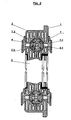
- Die Erfindung wird an Hand der Zeichnungen anschaulicher:
- Fig. 1:
- zeigt eine vertikale Schnittansicht durch einen erfindungsgemäßen Fensterflügel in einer einfachen Ausstattungsvariante zur manuellen Einstellung der Durchlüftung durch die Rahmenprofile.
- Fig. 2:
- zeigt in gleicher Ansicht wie in
Fig. 1 den gleichen Fensterflügel mit einer komfortableren Ausstattungsvariante zur elektromechanisch einstellbaren Durchlüftung durch die Rahmenprofile. - Fig. 3:
-
Fig. 3 zeigt die zur Steuerung der Durchlüftung gemäßFig. 2 in die Rahmenprofile eingebaute Baugruppe in perspektivischer Explosionsdarstellung. - Wie in
Fig. 1 undFig 2 gut ersichtlich, ist das Hohlprofil 4 in einem entlang der horizontalen Rahmenprofile 1, 2 verlaufenden Hohlraum angeordnet, welcher durch eine Nut 1.1 im horizontalen Rahmenprofil 1 des inneren Teilflügels und eine Nut 2.1 im horizontalen Rahmenprofil 2 des äußeren Teilflügels gebildeten wird. Das Hohlprofil 4 liegt mit seiner Außenmantelfläche über Dichtlippen 4.3, welche darauf in Profilrichtung verlaufen, an den Wänden der Nuten 1.1, 2.1 der Rahmenprofile 1, 2 auf Anschlag an. Vorzugsweise hat die äußere Umfangslinie der Querschnittsfläche des Hohlprofils 4 die Form eines regelmäßigen, geschlossenen Polygons. Die Nuten 1.1, 1.2 bilden einen Hohlraum mit der dazupassend komplementären Innenmantelfläche. Damit kann das Hohlprofil 4 in einigen wenigen, genau definierten Lagen, welche durch Verdrehung des Hohlprofils um seine Längsachse ineinander übergeführt werden, im Hohlraum an den horizontalen Rahmenprofilen 1, 2 angeordnet werden. - Der durch die beiden Nuten 1.1 und 2.1 gebildete Hohlraum in den Rahmenprofilen 1, 2 ist über Kanäle 5.1, 5.2, 5.3, welche gruppenweise in verschiedenen Richtungen davon weg verlaufen, mit dem Aussenraum, dem Innenraum und dem Flügelzwischenraum 3 verbunden. Die Mantelfläche des Hohlprofils 4 ist durch Bohrungen 4.1 mit dem inneren Hohlraum des Hohlprofils verbunden. Je nach Lage des Hohlprofils 4.1 in dem durch die Rahmenprofile 1, 2 umschlossenen Hohlraum liegen diese Bohrungen 4.1 in der Verlängerung von Kanalgruppen 5.1, 5.2, 5.3 in den Rahmenprofilen oder nicht. Dementsprechend werden diese Kanalgruppen bei der Bauweise gemäß
Fig. 1 mit dem inneren Hohlraum des Hohlprofils und in weiterer Folge untereinander verbunden, oder nicht. Zum Verändern der Lage des Hohlprofils 4 in den Rahmenprofilen 1, 2 werden die beiden Teilflügel des Fensters auseinandergeschwenkt, das Hohlprofil wird aus jener Nut 1.1 oder 2.1 herausgenommen, in welcher es sich nach dem Aufschwenken befindet, dann wird es um seine Längsachse in die gewünschte Lage verdreht, wieder in die Nut eingesetzt, und die Teilflügel werden wieder zueinander geschwenkt und aneinander arretiert. - Diese Art der Verstellung ist zwar sicher nicht die komfortabelste von den denk- und machbaren, aber sie ist sehr kostengünstig herstellbar, und sie reicht aus, um die Durchlässigkeit des Fensters beim ohnedies von Zeit zu Zeit erforderlichen Fensterputzen für die jeweilige Jahreszeit optimal einzustellen.
- Dadurch, dass das Hohlprofil 4 durch die Rahmenprofile beider Teilflügel getragen wird, können beide einzelnen Rahmenprofile 1, 2 mit relativ kleiner und einfacher Querschnittsfläche gebildet werden, und sind somit relativ kostengünstig.
- Dadurch, dass das Hohlprofil 4 gegenüber den Rahmenprofilen 1, 2 in eingebautem Zustand nicht beweglich zu sein braucht, kann es in einer Presspassung an diesen anliegen, und so einen Beitrag zur Steifheit des Rahmens liefern. Damit kann die gesamte umschlossene Querschnittsfläche der horizontalen Rahmenprofile gering gehalten werden.
- Wie in
Fig. 2 und auch inFig. 3 erkennbar, kann an Stelle von nur ausschließlich einem manuell zu verstellenden Hohlprofil 4, auch eine Baugruppe aus einem Hohlprofil und einem darin bzw. daran angeordneten elektronisch steuerbaren, elektromechanisch angetriebenen Ventilschieberteil 7 eingebaut werden. - Im dargestellten Beispiel hat die zentrale innere Hohlkammer des Hohlprofils 4 eine kreisförmige Querschnittsfläche. Der darin angeordnete Ventilschieberteil 7 hat etwa die Form eines Rundstabes. Er ist in Längsrichtung mit einer durchgehenden Bohrung versehen, und diese ist durch mehrere Raster von radial verlaufenden Bohrungen 7.1 mit der Mantelfläche verbunden. Innerhalb der einzelnen, in Längsrichtung verlaufenden Raster von radial verlaufenden Bohrungen 7.1, sind die Bohrungen zur gleichen Umfangsseite des Ventilschiebers 7 hin ausgerichtet. Zwischen den Öffnungen der einzelnen Raster von Bohrungen 7.1 an der Mantelfläche des Ventilschieberteiles 7 verlaufen in Längsrichtung des Ventilschiebers 7 Bürstenstreifen 7.2. Diese überbrücken den Spalt zwischen der Außenmantelfläche des Ventilschieber 7 und der Innenmantelfläche des Hohlprofils 4, und bilden dabei sowohl eine Dichtung, als auch eine Gleitführung für die Drehbewegung des Ventilschiebers 7 um seine Längsachse. Natürlich ist es auch möglich, diese Funktionen zu realisieren, indem die Passung des Ventilschiebers 7 im Hohlprofil 4 als enge Spielpassung ausgeführt wird; dabei besteht allerdings die erhöhte Gefahr von zu starker Reibung in Folge der Wirkung von Staubpartikeln.
- Die Bohrungen 7.1 im Ventilschieber 7 haben in Bezug auf die Bohrungen 4.1 die gleiche Funktion, wie die schon weiter oben beschriebene Funktion der Bohrungen 4.1 des Hohlprofils 4 in Bezug auf die Kanäle 5.1, 5.2, 5.3 in den Rahmenprofilen 1, 2. Das heißt, je nach Stellung des Ventilschiebers 7.1 werden die einzelnen Gruppen der Bohrungen 4.1 in der Mantelfläche des Hohlprofils 4 mit dem inneren Hohlraum des Ventilschiebers und ggf. in weiterer Folge mit einer anderen Gruppe von Bohrungen 4.1 verbunden, oder nicht. Wenn ein Ventilschieber 7 angewendet wird, dann ist das Hohlprofil 4 so in den Rahmenprofilen 1, 2 anzuordnen, dass jede Kanalgruppe 5.1, 5.2, 5.3 in den Rahmenprofilen durch eine Gruppe von Bohrungen 4.1 an der Mantelfläche des Hohlprofils fortgesetzt wird. Die Schaltung der Luftströme erfolgt dann durch Verdrehung des Ventilschiebers 7 im Hohlprofil 4. Um dort Kurzschlüsse der Luftbereiche zwischen den Bohrungsgruppen 7.1 zu vermeiden, ist der Ventilschieber 7 stirnseitig mit im Umfang umlaufenden Abdichtungen 7.3 versehen, welche an den Bürstenstreifen 7.2 anliegen. Das Verdrehen des Ventilschiebers 7 im Hohlprofil 4 kann durch eine elektromechanischen Antriebseinheit 8 erfolgen (
Fig 3 ), welche idealerweise an einer Stirnseite des Hohlprofils 4 in dem durch die beiden Rahmenprofilen 1, 2 gemeinsam gebildeten Hohlraum angeordnet ist, die gleiche Außenkontur wie das Hohlprofil 4 hat, und über einen Wellenstumpf mit dem Ventilschieberteil 4 in Eingriff ist. Die elektromechanische Antriebseinheit beinhaltet jedenfalls einen in seiner Winkellage steuerbaren Elektromotor nebst Steuerungselektronik. Zusätzlich kann sie beispielsweise auch eine aufladbare Batterie beinhalten, welche beispielsweise durch ein an der Außenseite des Fensters angeordnetes Solarzellenmodul gespeist werden kann. Die Steuerungselektronik ist in verschiedensten Varianten denk- und machbar. Von einer einfachen Ausführung, welche nur auf Knopfdruck den Ventilschieber 7 um jeweils eine Rasterstellung weiterdreht, bis zu einem über Funk mit verteilt angeordneten Klimasensoren kommunizierendem Gerät, welches abhängig von den jeweiligen Messdaten die optimale Stellung des Ventilschiebers ermittelt und einstellt. - Jedenfalls ist der Vorgang des Aus- und Einbaus der verschiedenen Steuerungsteile in der durch die Rahmenprofile 1, 2 gebildeten Holkammer sehr einfach zu bewerkstelligen. Dadurch wird es für Anwender möglich, sich erst einfach ausgestattete Fenster mit kostengünstiger manueller Einstellbarkeit der Luftdurchlässigkeit anzuschaffen, und diese später - wenn es die finanzielle Situation besser gestattet - mit einer sehr hochwertigen, automatisch arbeitenden Baugruppe für die Steuerung nachzurüsten.
- Im allgemeinen ist es für das Klima in einem Raum schädlich, wenn er vollkommen von der Außenluft abgeschlossen ist. Man sollte daher für den Fall, dass die standardmäßigen Belüftungswege durch die Bohrungen 4.1 bzw. 7.1 geschlossen werden, eine sog. Mikrolüftung, also eine sehr langsame Lüftung vorsehen. Durch die Verwendung von Bürstendichtungen, wie den Bürstenstreifen 7.2 als Dichtflächen ist so eine Mikrolüftung realisierbar, da diese Bürsten nicht hermetisch abdichten. Wenn keine derartigen Dichtungen angewendet werden, empfiehlt es sich, eine Mikrolüftung beispielsweise durch sehr feine Bohrungen 4.2 bzw. 7.3 im Hohlprofil 4 bzw. Ventilschieber vorzusehen. Bei den in
Fig. 1 undFig. 2 dargestellten Anordnungen kann zwischen der weniger dichten Stellung "mit definierter Mikrolüftung" und der dichteren Stellung "ohne definierte Mikrolüftung" ausgewählt werden. - Vor allem damit sich beim Auseinanderschwenken der beiden Teilflügel das Hohlprofil 4 nicht ungewollt löst, empfiehlt es sich, die Befestigung des Hohlprofils 4 an einem der beiden Rahmenprofile 1, 2 in definierter Weise fester auszuführen als am anderen Rahmenprofil. Beispielsweise kann an einem Rahmenprofil eine engere Presspassung realisiert werden, oder eine Vertiefung vorgesehen werden, in welche bei der Montage eine Erhöhung des Hohlprofils einrastet.
- Um das Eindringen von Staub und Insekten in die der Lüftung dienenden Hohlräume an den Fensterprofilen zu vermeiden, ist es sinnvoll an den zum Innenraum und zum Aussenraum weisenden Öffnungen der Kanäle 5.1, 5.2, Filter 6 vorzusehen.
- Eine interessante Weiterentwicklung der Erfindung besteht darin, den zentralen Hohlraum im Hohlprofil 4 in der Querschnittsansicht nicht als konzentrischen Kreis um den Ventilschieber 7 anzuordnen, sondern mit einem sich über den Umfang verändernden Abstand dazu, weiche Dichtstreifen, beispielsweise Bürstenstreifen zwischen den einzelneri Gruppen von Bohrungen 7.1 an der Mantelfläche des Ventilschiebers vorzusehen, und den Ventilschiebers in schnelle Rotation zu versetzen. Damit kann nach dem Wirkungsprinzip einer Kolbenschieberpumpe Luft aktiv in gewünschter Weise gepumpt werden.
Claims (13)
- Fensterflügel, welcher aus einem inneren und einem äußeren Teilflügel besteht, wobei die beiden Teilflügel voneinander trennbar sind, und wobei jeder Teilflügel mindestens eine Scheibe aufweist und zwischen den Flügeln ein Scheibenzwischenraum liegt, wobei im oberen Rahmenprofil (1, 2) und im unteren Rahmenprofil des Fensterflügels ein sich in Profilrichtung erstreckender Hohlraum angeordnet ist, welcher über jeweils eine Gruppe von Kanälen 5.1, 5.2, 5.3, die in die Mantelfläche des Hohlraums münden, mit dem Innenraum, dem Aussenraum und dem Scheibenzwischenraum in Verbindung steht, wobei sich in diesem Hohlraum ein Hohlprofit (4) erstreckt, welches mit seiner Außenmantelfläche an der Mantelfläche dieses Hohlraums anliegt, wobei die Mantelfläche des Hohlprofils (4) durch Bohrungen durchbrochen ist, wobei die Lage des Hohlprofils (4) im Hohlraum des Fensterrahmenprofils zwischen mehreren Stellungen wählbar ist, und wobei je nach Stellungen Bohrungen in der Mantelfläche des Hohlprofils (4) an Mündungen der Kanäle im Rahmenprofil des Fensterflügels zu liegen kommen, oder nicht, gekennzeichnet dadurch, dass die Mantelfläche des das Hohlprofil (4) umschließenden Hohlraumes durch einen Nut (1.1) im Rahmenprofil (1) des inneren Teilflügels und eine Nut (2.1) im Rahmenprofil (2) des äußeren Teilflügels gemeinsam gebildet wird.
- Fensterflügel nach Anspruch 1, gekennzeichnet dadurch, dass das Hohlprofil (4) an den Nuten (1.1, 2.1) der Rahmenprofile (1, 2) auf Presspassung anliegt.
- Fensterflügel nach Anspruch 1 oder 2, gekennzeichnet dadurch, dass das Hohlprofil (4) an einem der beiden Rahmenprofile (1, 2) in definierter Weise fester befestigt ist als an dem anderen.
- Fensterflügel nach einem der Ansprüche 1 bis 3, gekennzeichnet dadurch, dass sich die verschiedenen möglichen Stellungen des Hohlprofils (4) im Hohlraum im Rahmenprofil des Fensterflügels dadurch unterscheiden, dass das Hohlprofil 4 um eine in Profilrichtung liegende Achse geschwenkt ist.
- Fensterflügel nach einem der vorgenannten Ansprüche, gekennzeichnet dadurch, dass die Außenkontur des Hohlprofils (4) ein geschlossener Polygonzug ist.
- Fensterflügel nach Anspruch 5, gekennzeichnet dadurch, dass der Polygonzug regelmäßiges Vieleck mit einer geraden Seitenanzahl ist.
- Fensterflügel nach Anspruch 6, gekennzeichnet dadurch, dass das regelmäßige Vieleck ein Achteck ist.
- Fensterflügel nach einem der vorhergehenden Ansprüche, gekennzeichnet dadurch, dass im Hohlraum des Holprofils (4) ein Ventilschieber (7) eingesetzt ist, welcher wiederum die Form eines Hohlprofils hat, dessen Mantelfläche durch Gruppen von Bohrungen (7.1) mit dem inneren Hohlraum verbunden ist, wobei dieser Ventilschieber (7) an der Innenmantelfläche des Hohlprofils (4) um eine in Profilrichtung liegende Achse drehbar gelagert ist, wobei unterschiedliche Gruppen von Öffnungen von Bohrungen (7.1) an der Mantelfläche des Ventilschiebers (7) durch Dichtmittel (7.2) voneinander getrennt sind, wobei sich diese Dichtmittel (7.2) längs der Mantelfläche des Profilschiebers bis zur Innenmantelfläche des Hohlprofils (4) erstrecken, und wobei je nach Drehstellung des Ventilschiebers (7) Gruppen von Bohrungen (7.1) im Ventilschieber an Gruppen von Bohrungen (4.1) am Hohlprofil (4) anliegen oder nicht.
- Fensterflügel nach Anspruch 8, gekennzeichnet dadurch, dass die Dichtmittel (7.2) auch die Lagerflächen für die Drehbewegung des Ventilschiebers (7) im Hohlprofil (4) bilden.
- Fensterflügel nach Anspruch 8 oder 9, gekennzeichnet dadurch, dass die Dichtmittel (7.2) Bürstenstreifen sind.
- Fensterflügel nach einem der Ansprüche 8 bis 10, gekennzeichnet dadurch, dass im Hohlraum des Rahmenprofils eine steuerbare elektromechanische Antriebseinheit (8) mit in Profilrichtung ausgerichteter Abtriebswelle angeordnet ist, welche mit dem Ventilschieber (7) in Eingriff ist.
- Fensterflügel nach Anspruch 11, gekennzeichnet dadurch, dass sich die Spaltbreite zwischen der Mantelfläche des Ventilschiebers (7) und der Innenmantelfläche des Hohlprofils (4) über den Umfang des Ventilschiebers ändert, und dass der Spalt durch weiche Dichtmittel (7.2) überbrückt wird.
- Fensterflügel nach einem der vorhergehenden Ansprüche, gekennzeichnet dadurch, dass das Hohlprofil (4) und/oder der Ventilschieber (7) mit radialen Bohrungen (4.2, 7.3) versehen ist, deren Querschnittsfläche wesentlich geringer ist als die Querschnittsfläche der Bohrungen (4.1, 7.1).
Applications Claiming Priority (2)
| Application Number | Priority Date | Filing Date | Title |
|---|---|---|---|
| AT17752005A AT502747B1 (de) | 2005-10-31 | 2005-10-31 | Fensterflügel mit einstellbarer durchlüftung |
| PCT/AT2006/000445 WO2007051215A1 (de) | 2005-10-31 | 2006-10-27 | Fenster mit einstellbarer durchlüftung |
Publications (2)
| Publication Number | Publication Date |
|---|---|
| EP1951982A1 EP1951982A1 (de) | 2008-08-06 |
| EP1951982B1 true EP1951982B1 (de) | 2012-12-26 |
Family
ID=37857163
Family Applications (1)
| Application Number | Title | Priority Date | Filing Date |
|---|---|---|---|
| EP06804373A Not-in-force EP1951982B1 (de) | 2005-10-31 | 2006-10-27 | Fenster mit einstellbarer durchlüftung |
Country Status (3)
| Country | Link |
|---|---|
| EP (1) | EP1951982B1 (de) |
| AT (1) | AT502747B1 (de) |
| WO (1) | WO2007051215A1 (de) |
Families Citing this family (3)
| Publication number | Priority date | Publication date | Assignee | Title |
|---|---|---|---|---|
| DE102007012230A1 (de) * | 2007-03-12 | 2008-09-18 | Josef Westermann | Rahmen mit Lüfterelement und Verfahren zur Herstellung eines Rahmens mit Lüfterelement |
| DK2235312T3 (da) * | 2007-12-19 | 2012-01-23 | Vkr Holding As | Vindue med et ventilationsrør |
| FR3127508B1 (fr) * | 2021-09-27 | 2023-08-25 | Akerib Andre | Dispositif de panneau vitré et procédé d'implantation associé |
Family Cites Families (5)
| Publication number | Priority date | Publication date | Assignee | Title |
|---|---|---|---|---|
| DE3043783C2 (de) * | 1980-11-20 | 1982-12-16 | Alfred Dipl.-Ing. 5300 Bonn Wetzel | Schall- und wärmeisolierendes Fenster mit Schalldämmlüftung |
| DE3109811A1 (de) * | 1981-03-13 | 1982-11-18 | Wilhelm Weidtmann Gmbh & Co Kg, 5620 Velbert | Waerme- und schallschutzfenster mit vorrichtungen, die im taktverfahren nach dem thermo-syphon-prinzip eine raum be- und entlueftung mit waermerueckgewinnung aus der abluft ermoeglichen |
| DE3216581C2 (de) * | 1982-05-04 | 1985-05-09 | Alfred Dipl.-Ing. 5300 Bonn Wetzel | Schall- und wärmeisolierendes Verbundfenster mit Schalldämmlüftung |
| ATE46213T1 (de) * | 1984-06-08 | 1989-09-15 | Wetzel Alfred | Schall-und waermeisolierendes verbundfenster mit schalldaemmlueftung. |
| ATA6412003A (de) * | 2003-04-28 | 2004-10-15 | Dietrich Anton Fuchs | Fenster |
-
2005
- 2005-10-31 AT AT17752005A patent/AT502747B1/de not_active IP Right Cessation
-
2006
- 2006-10-27 WO PCT/AT2006/000445 patent/WO2007051215A1/de not_active Ceased
- 2006-10-27 EP EP06804373A patent/EP1951982B1/de not_active Not-in-force
Also Published As
| Publication number | Publication date |
|---|---|
| EP1951982A1 (de) | 2008-08-06 |
| WO2007051215A1 (de) | 2007-05-10 |
| AT502747A1 (de) | 2007-05-15 |
| AT502747B1 (de) | 2010-10-15 |
Similar Documents
| Publication | Publication Date | Title |
|---|---|---|
| DE102012101175B4 (de) | Drosseleinrichtung für den Luftdurchsatz durch einen Lufteinlass | |
| DE4143036A1 (de) | Belueftungseinrichtung fuer raeume | |
| EP1498568A1 (de) | Mehrscheibenfenster mit steuerbaren, durch das Rahmenprofil hindurch führenden Luftkanälen | |
| EP2780529B1 (de) | Lueftungsgeraet fuer den profilierten blendrahmen eines fluegels und luft-austauschverfahren am fenster | |
| DE19752019A1 (de) | Belüftungsvorrichtung und Belüftungssystem | |
| EP1837477B1 (de) | Fenster oder Tür mit Lüftung | |
| AT502747B1 (de) | Fensterflügel mit einstellbarer durchlüftung | |
| EP4124717B1 (de) | Lüftungsvorrichtung für ein fenster oder eine tür | |
| EP1809847B1 (de) | Rahmen, insbesonderen für eine tür, ein fenster oder ein fassadenelement | |
| DE202004006461U1 (de) | Stellorgan mit einer Einrichtung zur gedämpften Betätigung | |
| DE102009020597A1 (de) | Aufbau einer Doppelverglasung mit integrierter Jalousie | |
| EP2199526B1 (de) | Fenster oder Tür mit einem Blend- und Flügelrahmen | |
| DE3432457C2 (de) | ||
| DE19848944C1 (de) | Rolladenpanzer | |
| AT231119B (de) | Vorrichtung zum Belüften von Räumen | |
| DE2314829A1 (de) | Luftfoerdersystem, insbesondere raumluefter | |
| WO2010069666A1 (de) | Lüftungsvorrichtung für ein fenster oder eine tür | |
| EP4403839B1 (de) | Lüftungseinrichtung für ein gebäude sowie verfahren zum betreiben einer lüftungseinrichtung | |
| EP3995662B1 (de) | Gebäudeöffnungs-schliesselement mit einem automatisch relativ zu einem blendrahmen verstellbaren flügel- und/oder schieberahmen | |
| EP1167677B1 (de) | Zwangsbelüftetes Fenster | |
| EP0935047B1 (de) | Lüftungssystem an Tür- oder Fensterrahmen | |
| EP2129856B1 (de) | Rahmen mit lüfterelement zur verwendung in einer wandöffnung | |
| DE29903263U1 (de) | Vorbaurolladen | |
| AT505979A2 (de) | Mehrflügeliges bzw. mehrscheibiges fenster- türen- oder fassadenflächenelement | |
| DE202016004272U1 (de) | Rauchabzugsvorrichtung |
Legal Events
| Date | Code | Title | Description |
|---|---|---|---|
| PUAI | Public reference made under article 153(3) epc to a published international application that has entered the european phase |
Free format text: ORIGINAL CODE: 0009012 |
|
| 17P | Request for examination filed |
Effective date: 20080520 |
|
| AK | Designated contracting states |
Kind code of ref document: A1 Designated state(s): AT BE BG CH CY CZ DE DK EE ES FI FR GB GR HU IE IS IT LI LT LU LV MC NL PL PT RO SE SI SK TR |
|
| RAP1 | Party data changed (applicant data changed or rights of an application transferred) |
Owner name: FUCHS, DIETRICH ANTON |
|
| RIN1 | Information on inventor provided before grant (corrected) |
Inventor name: FUCHS, DIETRICH ANTON |
|
| DAX | Request for extension of the european patent (deleted) | ||
| GRAP | Despatch of communication of intention to grant a patent |
Free format text: ORIGINAL CODE: EPIDOSNIGR1 |
|
| GRAS | Grant fee paid |
Free format text: ORIGINAL CODE: EPIDOSNIGR3 |
|
| GRAA | (expected) grant |
Free format text: ORIGINAL CODE: 0009210 |
|
| AK | Designated contracting states |
Kind code of ref document: B1 Designated state(s): AT BE BG CH CY CZ DE DK EE ES FI FR GB GR HU IE IS IT LI LT LU LV MC NL PL PT RO SE SI SK TR |
|
| REG | Reference to a national code |
Ref country code: GB Ref legal event code: FG4D Free format text: NOT ENGLISH |
|
| REG | Reference to a national code |
Ref country code: CH Ref legal event code: EP |
|
| REG | Reference to a national code |
Ref country code: AT Ref legal event code: REF Ref document number: 590594 Country of ref document: AT Kind code of ref document: T Effective date: 20130115 |
|
| REG | Reference to a national code |
Ref country code: DE Ref legal event code: R096 Ref document number: 502006012363 Country of ref document: DE Effective date: 20130228 |
|
| PG25 | Lapsed in a contracting state [announced via postgrant information from national office to epo] |
Ref country code: LT Free format text: LAPSE BECAUSE OF FAILURE TO SUBMIT A TRANSLATION OF THE DESCRIPTION OR TO PAY THE FEE WITHIN THE PRESCRIBED TIME-LIMIT Effective date: 20121226 Ref country code: SE Free format text: LAPSE BECAUSE OF FAILURE TO SUBMIT A TRANSLATION OF THE DESCRIPTION OR TO PAY THE FEE WITHIN THE PRESCRIBED TIME-LIMIT Effective date: 20121226 Ref country code: FI Free format text: LAPSE BECAUSE OF FAILURE TO SUBMIT A TRANSLATION OF THE DESCRIPTION OR TO PAY THE FEE WITHIN THE PRESCRIBED TIME-LIMIT Effective date: 20121226 |
|
| REG | Reference to a national code |
Ref country code: CH Ref legal event code: PUE Owner name: ROLIC GMBH AND CO. KG, DE Free format text: FORMER OWNER: FUCHS, DIETRICH ANTON, AT Ref country code: CH Ref legal event code: NV Representative=s name: WAGNER PATENT AG, CH |
|
| RAP2 | Party data changed (patent owner data changed or rights of a patent transferred) |
Owner name: ROLIC GMBH & CO. KG |
|
| RIN2 | Information on inventor provided after grant (corrected) |
Inventor name: ROLIC GMBH & CO. KG |
|
| REG | Reference to a national code |
Ref country code: LT Ref legal event code: MG4D |
|
| REG | Reference to a national code |
Ref country code: NL Ref legal event code: VDEP Effective date: 20121226 |
|
| PG25 | Lapsed in a contracting state [announced via postgrant information from national office to epo] |
Ref country code: GR Free format text: LAPSE BECAUSE OF FAILURE TO SUBMIT A TRANSLATION OF THE DESCRIPTION OR TO PAY THE FEE WITHIN THE PRESCRIBED TIME-LIMIT Effective date: 20130327 Ref country code: LV Free format text: LAPSE BECAUSE OF FAILURE TO SUBMIT A TRANSLATION OF THE DESCRIPTION OR TO PAY THE FEE WITHIN THE PRESCRIBED TIME-LIMIT Effective date: 20121226 Ref country code: SI Free format text: LAPSE BECAUSE OF FAILURE TO SUBMIT A TRANSLATION OF THE DESCRIPTION OR TO PAY THE FEE WITHIN THE PRESCRIBED TIME-LIMIT Effective date: 20121226 |
|
| REG | Reference to a national code |
Ref country code: DE Ref legal event code: R081 Ref document number: 502006012363 Country of ref document: DE Owner name: ROLIC GMBH & CO. KG, DE Free format text: FORMER OWNER: FUCHS, DIETRICH ANTON, YBBSITZ, AT Effective date: 20130514 |
|
| PG25 | Lapsed in a contracting state [announced via postgrant information from national office to epo] |
Ref country code: IS Free format text: LAPSE BECAUSE OF FAILURE TO SUBMIT A TRANSLATION OF THE DESCRIPTION OR TO PAY THE FEE WITHIN THE PRESCRIBED TIME-LIMIT Effective date: 20130426 Ref country code: CZ Free format text: LAPSE BECAUSE OF FAILURE TO SUBMIT A TRANSLATION OF THE DESCRIPTION OR TO PAY THE FEE WITHIN THE PRESCRIBED TIME-LIMIT Effective date: 20121226 Ref country code: BG Free format text: LAPSE BECAUSE OF FAILURE TO SUBMIT A TRANSLATION OF THE DESCRIPTION OR TO PAY THE FEE WITHIN THE PRESCRIBED TIME-LIMIT Effective date: 20130326 Ref country code: SK Free format text: LAPSE BECAUSE OF FAILURE TO SUBMIT A TRANSLATION OF THE DESCRIPTION OR TO PAY THE FEE WITHIN THE PRESCRIBED TIME-LIMIT Effective date: 20121226 Ref country code: ES Free format text: LAPSE BECAUSE OF FAILURE TO SUBMIT A TRANSLATION OF THE DESCRIPTION OR TO PAY THE FEE WITHIN THE PRESCRIBED TIME-LIMIT Effective date: 20130406 Ref country code: CY Free format text: LAPSE BECAUSE OF FAILURE TO SUBMIT A TRANSLATION OF THE DESCRIPTION OR TO PAY THE FEE WITHIN THE PRESCRIBED TIME-LIMIT Effective date: 20121226 Ref country code: EE Free format text: LAPSE BECAUSE OF FAILURE TO SUBMIT A TRANSLATION OF THE DESCRIPTION OR TO PAY THE FEE WITHIN THE PRESCRIBED TIME-LIMIT Effective date: 20121226 |
|
| PG25 | Lapsed in a contracting state [announced via postgrant information from national office to epo] |
Ref country code: PL Free format text: LAPSE BECAUSE OF FAILURE TO SUBMIT A TRANSLATION OF THE DESCRIPTION OR TO PAY THE FEE WITHIN THE PRESCRIBED TIME-LIMIT Effective date: 20121226 Ref country code: NL Free format text: LAPSE BECAUSE OF FAILURE TO SUBMIT A TRANSLATION OF THE DESCRIPTION OR TO PAY THE FEE WITHIN THE PRESCRIBED TIME-LIMIT Effective date: 20121226 Ref country code: PT Free format text: LAPSE BECAUSE OF FAILURE TO SUBMIT A TRANSLATION OF THE DESCRIPTION OR TO PAY THE FEE WITHIN THE PRESCRIBED TIME-LIMIT Effective date: 20130426 Ref country code: RO Free format text: LAPSE BECAUSE OF FAILURE TO SUBMIT A TRANSLATION OF THE DESCRIPTION OR TO PAY THE FEE WITHIN THE PRESCRIBED TIME-LIMIT Effective date: 20121226 |
|
| REG | Reference to a national code |
Ref country code: GB Ref legal event code: 732E Free format text: REGISTERED BETWEEN 20130808 AND 20130814 |
|
| PG25 | Lapsed in a contracting state [announced via postgrant information from national office to epo] |
Ref country code: DK Free format text: LAPSE BECAUSE OF FAILURE TO SUBMIT A TRANSLATION OF THE DESCRIPTION OR TO PAY THE FEE WITHIN THE PRESCRIBED TIME-LIMIT Effective date: 20121226 |
|
| PLBE | No opposition filed within time limit |
Free format text: ORIGINAL CODE: 0009261 |
|
| STAA | Information on the status of an ep patent application or granted ep patent |
Free format text: STATUS: NO OPPOSITION FILED WITHIN TIME LIMIT |
|
| REG | Reference to a national code |
Ref country code: AT Ref legal event code: PC Ref document number: 590594 Country of ref document: AT Kind code of ref document: T Owner name: ROLIC GMBH & CO. KG, DE Effective date: 20130917 |
|
| 26N | No opposition filed |
Effective date: 20130927 |
|
| PG25 | Lapsed in a contracting state [announced via postgrant information from national office to epo] |
Ref country code: IT Free format text: LAPSE BECAUSE OF FAILURE TO SUBMIT A TRANSLATION OF THE DESCRIPTION OR TO PAY THE FEE WITHIN THE PRESCRIBED TIME-LIMIT Effective date: 20121226 |
|
| REG | Reference to a national code |
Ref country code: DE Ref legal event code: R097 Ref document number: 502006012363 Country of ref document: DE Effective date: 20130927 |
|
| REG | Reference to a national code |
Ref country code: CH Ref legal event code: PCAR Free format text: NEW ADDRESS: BAECHERSTRASSE 9, 8832 WOLLERAU (CH) |
|
| BERE | Be: lapsed |
Owner name: FUCHS, DIETRICH ANTON Effective date: 20131031 |
|
| PG25 | Lapsed in a contracting state [announced via postgrant information from national office to epo] |
Ref country code: MC Free format text: LAPSE BECAUSE OF FAILURE TO SUBMIT A TRANSLATION OF THE DESCRIPTION OR TO PAY THE FEE WITHIN THE PRESCRIBED TIME-LIMIT Effective date: 20121226 |
|
| REG | Reference to a national code |
Ref country code: IE Ref legal event code: MM4A |
|
| REG | Reference to a national code |
Ref country code: FR Ref legal event code: ST Effective date: 20140630 |
|
| PG25 | Lapsed in a contracting state [announced via postgrant information from national office to epo] |
Ref country code: FR Free format text: LAPSE BECAUSE OF NON-PAYMENT OF DUE FEES Effective date: 20131031 |
|
| PG25 | Lapsed in a contracting state [announced via postgrant information from national office to epo] |
Ref country code: BE Free format text: LAPSE BECAUSE OF NON-PAYMENT OF DUE FEES Effective date: 20131031 |
|
| PG25 | Lapsed in a contracting state [announced via postgrant information from national office to epo] |
Ref country code: IE Free format text: LAPSE BECAUSE OF NON-PAYMENT OF DUE FEES Effective date: 20131027 |
|
| PGFP | Annual fee paid to national office [announced via postgrant information from national office to epo] |
Ref country code: CH Payment date: 20141024 Year of fee payment: 9 Ref country code: DE Payment date: 20141104 Year of fee payment: 9 Ref country code: GB Payment date: 20141024 Year of fee payment: 9 |
|
| PGFP | Annual fee paid to national office [announced via postgrant information from national office to epo] |
Ref country code: AT Payment date: 20141022 Year of fee payment: 9 |
|
| PG25 | Lapsed in a contracting state [announced via postgrant information from national office to epo] |
Ref country code: TR Free format text: LAPSE BECAUSE OF FAILURE TO SUBMIT A TRANSLATION OF THE DESCRIPTION OR TO PAY THE FEE WITHIN THE PRESCRIBED TIME-LIMIT Effective date: 20121226 |
|
| PG25 | Lapsed in a contracting state [announced via postgrant information from national office to epo] |
Ref country code: LU Free format text: LAPSE BECAUSE OF NON-PAYMENT OF DUE FEES Effective date: 20131027 Ref country code: HU Free format text: LAPSE BECAUSE OF FAILURE TO SUBMIT A TRANSLATION OF THE DESCRIPTION OR TO PAY THE FEE WITHIN THE PRESCRIBED TIME-LIMIT; INVALID AB INITIO Effective date: 20061027 |
|
| REG | Reference to a national code |
Ref country code: DE Ref legal event code: R119 Ref document number: 502006012363 Country of ref document: DE |
|
| REG | Reference to a national code |
Ref country code: CH Ref legal event code: PL |
|
| REG | Reference to a national code |
Ref country code: AT Ref legal event code: MM01 Ref document number: 590594 Country of ref document: AT Kind code of ref document: T Effective date: 20151027 |
|
| GBPC | Gb: european patent ceased through non-payment of renewal fee |
Effective date: 20151027 |
|
| PG25 | Lapsed in a contracting state [announced via postgrant information from national office to epo] |
Ref country code: LI Free format text: LAPSE BECAUSE OF NON-PAYMENT OF DUE FEES Effective date: 20151031 Ref country code: DE Free format text: LAPSE BECAUSE OF NON-PAYMENT OF DUE FEES Effective date: 20160503 Ref country code: CH Free format text: LAPSE BECAUSE OF NON-PAYMENT OF DUE FEES Effective date: 20151031 Ref country code: GB Free format text: LAPSE BECAUSE OF NON-PAYMENT OF DUE FEES Effective date: 20151027 |
|
| PG25 | Lapsed in a contracting state [announced via postgrant information from national office to epo] |
Ref country code: AT Free format text: LAPSE BECAUSE OF NON-PAYMENT OF DUE FEES Effective date: 20151027 |