EP1837537A2 - Kugelschalenlagervorrichtung - Google Patents
Kugelschalenlagervorrichtung Download PDFInfo
- Publication number
- EP1837537A2 EP1837537A2 EP07005700A EP07005700A EP1837537A2 EP 1837537 A2 EP1837537 A2 EP 1837537A2 EP 07005700 A EP07005700 A EP 07005700A EP 07005700 A EP07005700 A EP 07005700A EP 1837537 A2 EP1837537 A2 EP 1837537A2
- Authority
- EP
- European Patent Office
- Prior art keywords
- outer ring
- split
- roller bearing
- ring split
- split part
- Prior art date
- Legal status (The legal status is an assumption and is not a legal conclusion. Google has not performed a legal analysis and makes no representation as to the accuracy of the status listed.)
- Withdrawn
Links
- 229910000831 Steel Inorganic materials 0.000 claims description 16
- 239000010959 steel Substances 0.000 claims description 16
- 239000011347 resin Substances 0.000 claims description 7
- 229920005989 resin Polymers 0.000 claims description 7
- 239000000314 lubricant Substances 0.000 claims description 5
- 238000005452 bending Methods 0.000 description 5
- 239000010705 motor oil Substances 0.000 description 5
- 238000003825 pressing Methods 0.000 description 5
- OKTJSMMVPCPJKN-UHFFFAOYSA-N Carbon Chemical compound [C] OKTJSMMVPCPJKN-UHFFFAOYSA-N 0.000 description 4
- 229910052799 carbon Inorganic materials 0.000 description 4
- 238000003780 insertion Methods 0.000 description 4
- 230000037431 insertion Effects 0.000 description 4
- 239000004071 soot Substances 0.000 description 4
- 238000005520 cutting process Methods 0.000 description 3
- 239000004519 grease Substances 0.000 description 3
- 210000000078 claw Anatomy 0.000 description 2
- 239000013013 elastic material Substances 0.000 description 2
- 239000000446 fuel Substances 0.000 description 2
- 238000000034 method Methods 0.000 description 2
- 238000005498 polishing Methods 0.000 description 2
- 239000011435 rock Substances 0.000 description 2
- 229910000838 Al alloy Inorganic materials 0.000 description 1
- 238000005299 abrasion Methods 0.000 description 1
- 229910052782 aluminium Inorganic materials 0.000 description 1
- XAGFODPZIPBFFR-UHFFFAOYSA-N aluminium Chemical compound [Al] XAGFODPZIPBFFR-UHFFFAOYSA-N 0.000 description 1
- 238000005255 carburizing Methods 0.000 description 1
- 230000000694 effects Effects 0.000 description 1
- 238000007373 indentation Methods 0.000 description 1
- 239000000463 material Substances 0.000 description 1
- 229910052751 metal Inorganic materials 0.000 description 1
- 239000002184 metal Substances 0.000 description 1
- 150000002739 metals Chemical class 0.000 description 1
- 238000005121 nitriding Methods 0.000 description 1
- 239000003921 oil Substances 0.000 description 1
- 239000002245 particle Substances 0.000 description 1
- 230000000149 penetrating effect Effects 0.000 description 1
- 239000000843 powder Substances 0.000 description 1
- 238000005096 rolling process Methods 0.000 description 1
- 238000000926 separation method Methods 0.000 description 1
- 239000010802 sludge Substances 0.000 description 1
Images


Classifications
-
- F—MECHANICAL ENGINEERING; LIGHTING; HEATING; WEAPONS; BLASTING
- F01—MACHINES OR ENGINES IN GENERAL; ENGINE PLANTS IN GENERAL; STEAM ENGINES
- F01L—CYCLICALLY OPERATING VALVES FOR MACHINES OR ENGINES
- F01L1/00—Valve-gear or valve arrangements, e.g. lift-valve gear
- F01L1/02—Valve drive
- F01L1/04—Valve drive by means of cams, camshafts, cam discs, eccentrics or the like
- F01L1/047—Camshafts
- F01L1/053—Camshafts overhead type
-
- F—MECHANICAL ENGINEERING; LIGHTING; HEATING; WEAPONS; BLASTING
- F01—MACHINES OR ENGINES IN GENERAL; ENGINE PLANTS IN GENERAL; STEAM ENGINES
- F01L—CYCLICALLY OPERATING VALVES FOR MACHINES OR ENGINES
- F01L1/00—Valve-gear or valve arrangements, e.g. lift-valve gear
- F01L1/02—Valve drive
- F01L1/04—Valve drive by means of cams, camshafts, cam discs, eccentrics or the like
- F01L1/047—Camshafts
-
- F—MECHANICAL ENGINEERING; LIGHTING; HEATING; WEAPONS; BLASTING
- F16—ENGINEERING ELEMENTS AND UNITS; GENERAL MEASURES FOR PRODUCING AND MAINTAINING EFFECTIVE FUNCTIONING OF MACHINES OR INSTALLATIONS; THERMAL INSULATION IN GENERAL
- F16C—SHAFTS; FLEXIBLE SHAFTS; ELEMENTS OR CRANKSHAFT MECHANISMS; ROTARY BODIES OTHER THAN GEARING ELEMENTS; BEARINGS
- F16C19/00—Bearings with rolling contact, for exclusively rotary movement
- F16C19/22—Bearings with rolling contact, for exclusively rotary movement with bearing rollers essentially of the same size in one or more circular rows, e.g. needle bearings
- F16C19/44—Needle bearings
- F16C19/46—Needle bearings with one row or needles
- F16C19/463—Needle bearings with one row or needles consisting of needle rollers held in a cage, i.e. subunit without race rings
-
- F—MECHANICAL ENGINEERING; LIGHTING; HEATING; WEAPONS; BLASTING
- F16—ENGINEERING ELEMENTS AND UNITS; GENERAL MEASURES FOR PRODUCING AND MAINTAINING EFFECTIVE FUNCTIONING OF MACHINES OR INSTALLATIONS; THERMAL INSULATION IN GENERAL
- F16C—SHAFTS; FLEXIBLE SHAFTS; ELEMENTS OR CRANKSHAFT MECHANISMS; ROTARY BODIES OTHER THAN GEARING ELEMENTS; BEARINGS
- F16C19/00—Bearings with rolling contact, for exclusively rotary movement
- F16C19/22—Bearings with rolling contact, for exclusively rotary movement with bearing rollers essentially of the same size in one or more circular rows, e.g. needle bearings
- F16C19/44—Needle bearings
- F16C19/46—Needle bearings with one row or needles
- F16C19/466—Needle bearings with one row or needles comprising needle rollers and an outer ring, i.e. subunit without inner ring
-
- F—MECHANICAL ENGINEERING; LIGHTING; HEATING; WEAPONS; BLASTING
- F16—ENGINEERING ELEMENTS AND UNITS; GENERAL MEASURES FOR PRODUCING AND MAINTAINING EFFECTIVE FUNCTIONING OF MACHINES OR INSTALLATIONS; THERMAL INSULATION IN GENERAL
- F16C—SHAFTS; FLEXIBLE SHAFTS; ELEMENTS OR CRANKSHAFT MECHANISMS; ROTARY BODIES OTHER THAN GEARING ELEMENTS; BEARINGS
- F16C33/00—Parts of bearings; Special methods for making bearings or parts thereof
- F16C33/30—Parts of ball or roller bearings
- F16C33/58—Raceways; Race rings
- F16C33/581—Raceways; Race rings integral with other parts, e.g. with housings or machine elements such as shafts or gear wheels
-
- F—MECHANICAL ENGINEERING; LIGHTING; HEATING; WEAPONS; BLASTING
- F16—ENGINEERING ELEMENTS AND UNITS; GENERAL MEASURES FOR PRODUCING AND MAINTAINING EFFECTIVE FUNCTIONING OF MACHINES OR INSTALLATIONS; THERMAL INSULATION IN GENERAL
- F16C—SHAFTS; FLEXIBLE SHAFTS; ELEMENTS OR CRANKSHAFT MECHANISMS; ROTARY BODIES OTHER THAN GEARING ELEMENTS; BEARINGS
- F16C33/00—Parts of bearings; Special methods for making bearings or parts thereof
- F16C33/30—Parts of ball or roller bearings
- F16C33/58—Raceways; Race rings
- F16C33/60—Raceways; Race rings divided or split, e.g. comprising two juxtaposed rings
-
- F—MECHANICAL ENGINEERING; LIGHTING; HEATING; WEAPONS; BLASTING
- F01—MACHINES OR ENGINES IN GENERAL; ENGINE PLANTS IN GENERAL; STEAM ENGINES
- F01L—CYCLICALLY OPERATING VALVES FOR MACHINES OR ENGINES
- F01L1/00—Valve-gear or valve arrangements, e.g. lift-valve gear
- F01L1/02—Valve drive
- F01L1/04—Valve drive by means of cams, camshafts, cam discs, eccentrics or the like
- F01L1/047—Camshafts
- F01L2001/0476—Camshaft bearings
-
- F—MECHANICAL ENGINEERING; LIGHTING; HEATING; WEAPONS; BLASTING
- F16—ENGINEERING ELEMENTS AND UNITS; GENERAL MEASURES FOR PRODUCING AND MAINTAINING EFFECTIVE FUNCTIONING OF MACHINES OR INSTALLATIONS; THERMAL INSULATION IN GENERAL
- F16C—SHAFTS; FLEXIBLE SHAFTS; ELEMENTS OR CRANKSHAFT MECHANISMS; ROTARY BODIES OTHER THAN GEARING ELEMENTS; BEARINGS
- F16C2360/00—Engines or pumps
- F16C2360/18—Camshafts
-
- F—MECHANICAL ENGINEERING; LIGHTING; HEATING; WEAPONS; BLASTING
- F16—ENGINEERING ELEMENTS AND UNITS; GENERAL MEASURES FOR PRODUCING AND MAINTAINING EFFECTIVE FUNCTIONING OF MACHINES OR INSTALLATIONS; THERMAL INSULATION IN GENERAL
- F16C—SHAFTS; FLEXIBLE SHAFTS; ELEMENTS OR CRANKSHAFT MECHANISMS; ROTARY BODIES OTHER THAN GEARING ELEMENTS; BEARINGS
- F16C33/00—Parts of bearings; Special methods for making bearings or parts thereof
- F16C33/30—Parts of ball or roller bearings
- F16C33/46—Cages for rollers or needles
- F16C33/4694—Single-split roller or needle cages
-
- F—MECHANICAL ENGINEERING; LIGHTING; HEATING; WEAPONS; BLASTING
- F16—ENGINEERING ELEMENTS AND UNITS; GENERAL MEASURES FOR PRODUCING AND MAINTAINING EFFECTIVE FUNCTIONING OF MACHINES OR INSTALLATIONS; THERMAL INSULATION IN GENERAL
- F16C—SHAFTS; FLEXIBLE SHAFTS; ELEMENTS OR CRANKSHAFT MECHANISMS; ROTARY BODIES OTHER THAN GEARING ELEMENTS; BEARINGS
- F16C35/00—Rigid support of bearing units; Housings, e.g. caps, covers
- F16C35/04—Rigid support of bearing units; Housings, e.g. caps, covers in the case of ball or roller bearings
- F16C35/042—Housings for rolling element bearings for rotary movement
-
- F—MECHANICAL ENGINEERING; LIGHTING; HEATING; WEAPONS; BLASTING
- F16—ENGINEERING ELEMENTS AND UNITS; GENERAL MEASURES FOR PRODUCING AND MAINTAINING EFFECTIVE FUNCTIONING OF MACHINES OR INSTALLATIONS; THERMAL INSULATION IN GENERAL
- F16C—SHAFTS; FLEXIBLE SHAFTS; ELEMENTS OR CRANKSHAFT MECHANISMS; ROTARY BODIES OTHER THAN GEARING ELEMENTS; BEARINGS
- F16C35/00—Rigid support of bearing units; Housings, e.g. caps, covers
- F16C35/04—Rigid support of bearing units; Housings, e.g. caps, covers in the case of ball or roller bearings
- F16C35/06—Mounting or dismounting of ball or roller bearings; Fixing them onto shaft or in housing
- F16C35/067—Fixing them in a housing
Definitions
- the present invention relates to a split roller bearing device that is disposed at a shaft support part mainly for a camshaft or a crankshaft in the engine of a vehicle.
- a camshaft is generally supported by a sliding bearing (e.g. see JP-A-11-148426 ); however, when a ball bearing is disposed at the shaft support part, instead of the sliding bearing, it has an effect on reducing the above-mentioned energy loss. According to estimates, when the engine operated under a specific condition (oil temperature: 40°C and number of revolutions: 300 rpm) with the sliding bearing and the ball bearing equipped, torque was reduced by 18% when the ball bearing was used as compared with when the sliding bearing was used.
- camshaft an assembly type and integral type are known.
- assembly type individual cams are assembled with a shaft body and in the integral type, a shaft body and cams are integrally formed.
- a ball bearing is mounted around the shaft body by press-fitting, in assembling cams with a shaft body.
- a split ball bearing such as a roller bearing in which bearing rings and a cage for rolling bodies are separated into two sections, is used, because cams are arranged in advance at each axial position on the shaft body.
- a split roller bearing device includes:
- a variety of means can be selected to fix the outer ring split part to the cap member and the outer ring split part may be fixed to the cap member by locking the circumferential ends of the outer ring split part to a portion of the cap member.
- the outer ring split part is inserted in arc-shaped recess of the cap member and the circumferential ends are locked to a portion of the cap member, which facilitates fixing the outer ring split part to the cap member.
- the outer ring split part may be fixed to the cap member by integrally forming the outer ring split part with the cap member. According to the fixing configuration, since the cap member is made of a resin, the weight and cost are reduced.
- a cage for rollers may be separated into two sections, but it is preferable for the cage to have only one cut at a circumferential position by way of a preferred embodiment.
- the cage having the above configuration may be mounted around the shaft body by opening the cut. According to the configuration, as compared with when a cage consists of two sections and the sections are combined at two circumferential positions, it is facilitated to mount the cage to the shaft body and the cap member and the outer ring section is considered as a part, so that the assembling becomes considerably easy.
- the outer ring split part of a steel plate.
- members that are mounted around the outer ring split part of a steel plate, including the cap member can be made of an inexpensive material with lower weight and hardness than the steel plate.
- the outer ring split part of a steel plate may be disposed at a side, a loading region, of the cap member, in the range of at least 90°. According to the configuration, in particular, it is not necessary to mount an outer ring split part of steel plate to the other portion of the outer ring, and the other portion of the outer ring may be disposed at the inside of the arc-shaped recess of the housing or the cap member.
- the outer ring split part of steel plate is mounted at the cap member disposed under the camshaft.
- the outer ring split part may be mounted at the housing.
- the outer ring split part of steel plate may be mounted to another member (e..g. housing), other than the cap member, corresponding to the cap member, within the load region.
- the split roller bearing device having the above configuration, other than the outer ring split part for the cap member, when another outer ring split part is mounted at the housing, the outer ring split parts for the cap member and the housing are connected in a ring shape.
- the outer ring split parts for the cap member and the housing are connected in a ring shape.
- the split roller bearing device having the above configuration, since a roller bearing is used, the surface pressure increases at the rotational contact portion, and the engine oil containing carbon soot, metallic abrasion powder, and sludge flows into inside, thereby the roller bearing may be early worn compared to those in which a sliding bearing is used.
- labyrinth is formed between the cap member or the outer ring split part fixed to the cap member and the shaft body and lubricant is filled in the labyrinth. According to the configuration, the engine oil can be prevented from flowing into inside the roller bearing by the lubricant and wear is considerably reduced at the rotational contact portion.
- a split roller bearing device includes:
- split roller bearing devices when it is intended to support rotatably a shaft body, such as a camshaft, two cage sections and two outer ring split parts in a split roller bearing are respectively connected in a ring shape around the shaft body and the outer ring is necessarily fixed to the housing by a cap member, such as a cam cap.
- the entire outer ring is fixed to the housing by fixing one of the outer ring split parts to the housing through the attachment portions. Therefore, it is possible to reduce the number of parts and easily simply arrange the split roller bearing device to support rotatably the shaft body.
- a cap member such as a cam cap, which is necessary for split roller bearings in the related art, is not needed for the split roller bearing device, so that it is possible to reduce the number of parts, cost, and weight.
- the outer ring split part with the attachment portions is formed of a steel plate that has undergone hardening
- an attachment portion that protrudes radially outward from both circumferential ends of an arc portion of the raceway of the outer ring split part is integrally formed with the arc portion, and the outer ring split part with the attachment portions may be formed by pressing the steel plate, which considerably saves cost.
- an engaging portion is formed at both circumferential ends of the raceway of the outer ring split part with the attachment portions
- an engaged portion that is engageable with the engaging portion is formed at both circumferential ends of the raceway of another outer ring split part that is connected in a ring shape with the outer ring split part with the attachment portions
- the outer ring split parts are connected by engagement of the engaging portions and the engaged portions in a ring shape.
- the roller bearing is mounted around the shaft body, as though they are wound around the shaft body, and under this condition the roller bearing and the shaft body are attached to the housing. Therefore, it facilitates the operation for rotatably supporting the shaft body.
- the split roller bearing device having the above configuration, even though the outer ring split part with the attachment portions and the other outer ring split part are connected in a ring shape, noise may be made by rocking on the joint of the rollers when they pass in rotation the joint.
- recess faces which are recessed radially outward from the other portion in the raceway of the outer ring split parts, on the inner circumferential surfaces at the joint ends of the outer ring split part with the attachment portions and the other outer ring that is connected in a ring shape with the outer ring split part.
- inner ribs which axially restrict a cage with rollers held that is mounted on a inner circumferential side of the outer ring split part with the attachment portions, are formed at both axial sides of the outer ring split part.
- the cage with the rollers held is axially restricted and the roller bearing including the cage with the rollers held can be mounted around not only the smaller diameter portion formed on the shaft body (at the smaller diameter portion, the cage with the rollers held is axially restricted by the edge walls of both axial sides of the smaller diameter portion), but also the larger diameter portion formed on the shaft body and a portion having the same diameter as the other portion of the shaft body.
- the outer circumferential surface of the larger diameter portion functions as the inner ring, and the smaller diameter portion protrudes radially outward from the other portion of the shaft body, so that it is facilitated to grind and polish the inner ring and it is achievable to make the inner ring in high precision.
- the second aspect of the invention it is facilitated to support rotatably a shaft body by mounting a split roller bearing around the shaft body. Further, since a cap member, such as a cam cap, is not needed, the number of parts is reduced and the weight of the shaft support part and cost are reduced accordingly.
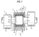
- FIG. 1 is a longitudinal cross-sectional side view of a split roller bearing device according to the first embodiment
- Fig. 2 is an exploded cross-sectional view showing the cross-section of each part exploded, taken along the line ii-ii of Fig. 1
- Fig. 3 is a perspective view of a cage with rollers.
- reference numerals 1 and 2 represent a camshaft and the entire split roller bearing device, respectively.
- the camshaft 1 is formed by integrally forming cams 12 with a shaft body 11 and the cams 12 in rotation press down corresponding cam followers (not shown) that are disposed under the cam 12.
- a two-stepped larger diameter portion consisting of a first larger diameter portion 11a and a second larger diameter portion 11b having a larger diameter than one of the first larger diameter portion 11a is formed at the support point for the shaft body 11.
- the split roller bearing device 2 is mounted around the shaft body 11 of the camshaft 1 at the support point and composed of a roller bearing 3 and a cam cap 5 (referred to as cap member in the claims) that fixes the roller bearing 3 between cam cap 5 and a housing 4.
- the roller bearing 3 includes a plurality of rollers 6, a cage 7 that holds the rollers 6 circumferentially at regular intervals, an outer ring consisting of two semicircular outer ring split parts 8A, 8B.
- the rollers 6 are arranged in contact with the outer circumference of the second larger diameter portion 11b of the shaft body 11, so that the outer circumference of the second larger diameter portion 11b operates as the inner ring of the roller bearing 3.
- Each of the outer ring split parts 8A, 8B is formed into a semi-circular arc by pressing a steel plate with a hardness of 55 HRC or more.
- the cam cap 5 similar to the housing 4, is made of light metals, such as aluminum or aluminum alloy. As shown in Fig. 2, the cam cap 5 has an arc portion 5a and fixing portions 5b that radially protrude outward from both circumferential ends of the arc portion 5a. Inner ribs 5c are formed at both axial sides of the arc portion 5a, radially protruding inward.
- the inner ribs 5c of the cam cap 5 protrude, close to the first larger diameter portion 11a of the camshaft 1, such that they cover axial sides of the cage 7 of the roller bearing 3 that is disposed inside the arc portion 5a of the cam cap 5 and a labyrinth 9 is formed between the inner rib 5c and the angular portion of the first larger diameter portion 11a.
- Lubricant (not shown), such as grease, is filed in the labyrinth 9.
- the outer ring split part 8A of the outer ring split parts 8A, 8B is fixed to the inner circumference of the arc portion 5a of the cam cap 5.
- locking portions 5d are formed on the inner circumference at both circumferential ends of the arc portion 5a of the cam cap 5 and the circumferential ends of the outer ring split part 8A are locked into the locking portions 5d. Accordingly, the outer ring split part 8A is fixed to the inner circumference of the arc portion 5a of the cam cap 5.
- the other outer ring split part 8B is mounted in an arc-shaped recess 4a formed on the housing 4. Similar to the cam cap 5, inner ribs 4b are formed at both axial sides of the arc-shaped recess 4a of the housing 4, radially protruding inward.
- the cage 7 of the roller bearing 3 is formed of an elastic material, such as a resin, and as shown in Figs.. 2 and 3, has a cut 71 at only one circumferential position.
- a fitting protrusion 7a is formed at an end of the cut 71 and a fitting recess 7b to fit the fitting protrusion 7a in is formed at the other end of the cut 71.
- inner ribs 7c are formed at both axial sides of the cage 7, radially protruding inward. The inner ribs 7c are axially locked by the second larger diameter portion 11b of the camshaft 1.
- the rollers 6 held by the cage 7 are mounted around the second larger diameter portion 11b of the camshaft 1.
- the cam cap 5 is disposed on the housing 4 and the cam cap 5 is fixed to the housing 4 by fasteners such as screws. Therefore, the camshaft 1 is rotatably supported by the roller bearing 3.
- the outer ring split part 8A and the cam cap 5 can be considered as one member, it is not necessary to separately assemble the outer ring split part 8A and the cam cap 5, so that their assembling can be conducted by only one process.
- the cage 7 and rollers 6 are axially held relative to the camshaft 1 and the cage 7 is also axially held by the inner rib 5c of the camshaft 5. Accordingly, the cage 7 and rollers 6 are axially held relative to the cam cap 5 and the housing 4, with being axially arranged with the second larger diameter portion 11b, the inner ring.
- the outer ring split part 8A is fixed to the cam cap 5 in the configuration of Fig. 2, while it may be fixed to the cam cap 5 by other members.
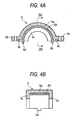
- Fig. 4A is a side view of a configuration of an outer ring split parts and a cam cap fixed according to second embodiment and Fig. 4B is a cross-sectional view taken along the line b-b of Fig. 4A.
- a cam cap 5 is made of a resin.
- An outer ring split part 8A has protrusions 8c that protrude radially outward from both circumferential ends. Protrusions 8d are formed at circumferential ends of the outer ring split part 8A by cutting and bending a portion of each of the protrusions 8c in the width direction.
- the outer ring split part 8A is integrally formed with a cam cap 5, so that it is fixed to the cam cap 5. According to the fixed configuration, it is possible to reduce the weight and cost because the cam cap 5 is made of a resin.
- the protrusions 8d of the outer ring split parts 8A are formed for arrangement with an outer ring split part 8B disposed at the housing 4 and is fitted in recess (not shown) that are formed at axial ends of the outer ring split part 8B at the housing 4. Further, when the outer ring split part 8A is integrally formed with the cam cap 5, the protrusions 8d is used to locate the outer ring split part 8A to a predetermined position in a forming mold.
- the outer ring split part 8A at the cam cap 5 and the outer ring split part 8B at the housing 4 is connected in a ring shape by the locking portions 5d.
- the locking portions 5d are not formed, as shown in Figs. 5 to 7, the ends of the outer ring split parts 8A, 8B are connected in a ring shape, face-to-face.
- recess faces on the inner circumferential surfaces of the joint ends of the outer ring split part 8A at the cam cap 5 and the outer ring split part 8B at the housing 4 such that they are recessed radially outward from the raceway of the other of the outer ring split parts 8A, 8B.
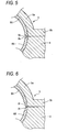
- Fig. 5 is a view illustrating the structure of a joint of outer ring split parts according to third embodiment.
- V-shaped sloped recess faces 8e are formed on the inner circumferential surfaces at the joint ends of the outer ring split parts 8A, 8B.
- Fig. 6 is a view illustrating the structure of a joint of outer ring split parts according to fourth embodiment.
- flat-wide recess faces 8f are formed on the inner circumferential surfaces at the joint ends of the outer ring split parts 8A, 8B such that they are recessed as indentation radially outward from the other of the outer ring split parts 8A.
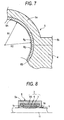
- Fig. 7 is a view illustrating the structure of a joint of outer ring split parts according to fifth embodiment.
- recess faces 8g are formed in an arc shape having a radius of curvature R2 larger than the radius of curvature R1 for the other portions of the outer ring split parts 8A, 8B, on the inner circumferential surfaces at the joint ends of the outer ring split parts 8A, 8B.
- the recess faces shown in Figs. 5 to 7 are formed by press finishing, but may be formed by grinding or bending.
- the labyrinth 9 are formed between the inner rib 5c of the cam cap 5 and the other larger diameter portion (first larger diameter portion 11a) of the camshaft 1.
- the inner ring is not necessarily formed in such a large diameter and may be formed in the same diameter as or smaller than the other portion of the shaft body 11 of the camshaft 1. Further, the labyrinth 9 may be formed radially outside the roller bearing 3.
- Fig. 8 is a view illustrating the structure of a labyrinth according to sixth embodiment.
- the roller bearing 3 is mounted around the portion having the same diameter as the portion other than the shaft body 11 and the inner ribs 5c of the cam cap 5 are located close to the outer circumferential surface of the shaft body 11, and the labyrinth 9 is formed between the above-mentioned outer circumferential surface and the inner circumference of the inner ribs 5c.
- the cage 7 has no inner rib at both axial sides.
- Fig. 9 is a view illustrating the structure of a labyrinth according to seventh embodiment.
- inner ribs 8h are formed at both axial sides of the outer ring split part 8A and the labyrinth 9 is formed between the inner circumference of the inner ribs 8h and the outer circumferential surface of shaft body 11.
- the cam cap 5 is the same in axial width as the outer ring split part 8A and has no inner rib at both axial sides.
- Fig. 10 is a view illustrating the structure of a labyrinth 9 according to eighth embodiment.
- the outer ring split part 8A is fitted between the inner ribs 5c at both axial ends of the cam cap 5, the inner ribs 8h extend radially inward at both axial sides of the outer ring split part 8A, and the labyrinth 9 is formed between the inner rib 8h and the outer circumferential surface of the shaft body 11.
- FIG. 11 is a longitudinal cross-sectional view of a split roller bearing device according to the ninth embodiment
- Fig. 12 is a cross-sectional view taken along the line ii-ii of Fig. 11
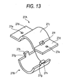
- Fig. 13 is an exploded perspective view of outer ring split parts
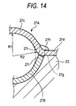
- Fig. 14 is an enlarged cross-sectional view illustrating the joint of the outer ring split parts.
- reference numerals 21, 22, and 23 represent a camshaft, the entire split roller bearing device, and a housing where the split roller bearing device 22 is placed, respectively.
- the camshaft 21 is formed by integrally forming cams 32 with a shaft body 31 and the cams 32 in rotation press down corresponding cam followers (not shown) that are disposed under the cams 32.
- a smaller diameter portion 31a is formed at the supported portion of the shaft body 31.
- the split roller bearing device 22 is mounted around the smaller diameter portion 31a of the shaft body 31 of the camshaft 21 and has a roller bearing 24.
- the roller bearing 24 includes a plurality of rollers 25, a cage 26 that holds the rollers 25 circumferentially at regular intervals, and an outer ring that is separated into two outer ring split parts 27A, 27B.
- the rollers 25 are arranged in contact with the outer circumference of the smaller diameter portion 31a of the shaft body 31. Accordingly, the outer circumference of the smaller diameter portion 31a operates as the inner ring of the roller bearing 24.
- the cage 26, may be separated into two sections.
- the cage 26 may be made of an elastic material, such as a resin, having a cut at only one axial position, so that it can be open in a C-shape in side view.
- the cage 26 is a little smaller in width than the smaller diameter portion 31a of the shaft body 31, and axially restricted by the edge walls at both sides of the smaller diameter portion 31a, with holding the rollers 25.
- the two outer ring split parts 27A, 27B that are connected in a ring shape are both made in a desired shape by pressing a steel plate that has undergone a hardening treatment such as carburizing or nitriding (for example, SCM 415).
- the outer ring split parts 27A, 27B each have a 1 to 4.5 mm thickness, a hardness above Hv 650 at the outermost surface. Further, they each have a residual compressive stress of 500 MPa to increase the fatigue strength.
- One of the outer ring split parts 27A, 27B i.e. the outer ring split part 27A (the upper outer ring split part in Figs. 11 to 13, and referred to as 'upper outer ring split part' hereafter) functions as a member for fixedly mounting the roller bearing 24 between the housing 23 and the upper outer ring split part itself and has integrally-formed attachment portions 27d to the housing 24.
- attachment portions 27d are integrally formed with the upper outer ring split part 27A at both continual circumferential ends of a half-circular arc portion 27c that is operable as a raceway, by bending the ends radially outward.
- the attachment portions 27d protrude outward in a line along a line passing through both circumferential ends of the arc portion 27c.
- An insertion hole 27e for a screw 28 is formed at each of the attachment portions 27d.
- Screw holes 23e are formed on attachment surfaces of the housing 23 (the upper surfaces in Figs. 11 and 12), corresponding to the screw insertion holes 27e at the attachment portions 27d.
- the entire roller bearing 24 including the upper outer ring split part 27A is fixedly mounted to the housing 23, by fixing the attachment portions 27d of the upper outer ring split part 27A to the housing 23 with appropriate devices or parts, such as the screws 28, with the attachment portions 27d placed on the upper surface of the housing 23.
- the other outer ring split part 27B of the outer ring split parts 27A, 27B (the lower outer ring split part in Figs. 11 to 13, referred to as lower outer ring split part' hereafter) is formed into a substantial arc shape and fitted in an arc-shaped recess 23a formed on the housing 23.
- engagement through holes 27f, engaging portions are formed at the boundaries between the arc portion 27c and the attachment portions 27d.
- engagement protrusions 27g, engaged portions with the engaging portions, which protrude circumferentially are formed at the circumferential ends of the lower outer ring split part 27B.
- the engagement protrusions 27g each has a claw 27h at the free ends and is fitted through the engagement holes 27f of the upper outer ring split part 27A.
- the upper outer ring split part 27A and lower outer ring split part 27B are connected in a ring shape and, as shown in Fig. 14, a recess face 27i that is radially recessed outward from the other portion of the raceway of the outer ring split parts 27A, 27B is formed on the inner circumferential surfaces the joint ends of the outer ring split parts 27A, 27B.
- the radius of curvature R2 of the inner circumferential surfaces the joint ends of the outer ring split parts 27A, 27B is larger than the radius of curvature R1 at the other portion of the raceway of the outer ring split parts 27A, 27B, so that the inner circumferential surfaces the joint ends turn out the recess faces 27i recessed radially outward.
- the recess faces 27i may be each formed in a flat wide surface or a surface that bends inversely to the arc portions 27c of the outer ring split parts 27A, 27B. Further, the recess faces 27i may be formed by pressing at the same time of forming the entire of the outer ring split parts 27A, 27B. Alternatively, the recess faces 27i may be formed separately by grinding or polishing after the pressing of the outer ring split parts 27A, 27B.
- the upper and lower outer ring split parts 27A, 27B are connected in a ring shape, around the rollers 25.
- the engagement protrusions 27g of the lower outer ring split part 27B are fitted through the engagement holes 27f of the upper ring split part 27A and the claws 27h of the engagement protrusions 27g are engaged with the peripheries outside the engagement holes 27f on a radially outside of the engagement holes 27f.
- the engagement protrusion 27g is prevented from falling out of the engagement holes 27f.
- the upper and lower outer ring split parts 27A, 27B are connected in a ring shape, without separating, and the entire roller bearing 24 including the outer ring split parts 27A, 27B is mounted around the smaller diameter portion 31a of the shaft body 31, as though they are wound around the shaft body 31.
- the attachment portions 27d of the upper outer ring split part 27A are placed on the upper surface of the housing 23. While the lower outer ring split part 27B is fixed in the arc-shaped recess 23a of the housing 23 through the upper outer ring split part 27A by fixing the attachment portions 27d to the housing 23 with screws 28, the entire roller bearing 24 including the outer ring split parts 27A, 27B is fixedly mounted around the housing 23, consequently, the camshaft 21 is rotatably supported by the roller bearing 24.
- the roller bearing 24 including the outer ring split parts 27A, 27b can be mounted around the camshaft 21 and it takes little efforts to maintain the roller bearing 24. As a result, it is facilitated to arrange the roller bearing 24 to rotatably support the camshaft 21.
- outer ring consisting of the outer ring split parts 27A, 27B is fixed to the housing 23 through a portion of the outer ring split part 27A (attachment portions 27d), it is not needed to use a cap member, such as cam cap, as in the related art, to fix the outer ring. Further, while the number of parts is reduced and it is possible to reduce cost and weight of the shaft support part accordingly.
- Fig. 15 is a view of a split roller bearing device according to tenth embodiment and a split roller bearing device 22 according to this embodiment is mounted around a larger diameter portion 31b of a shaft body 31 of a camshaft 21 and the outer circumference of the larger diameter portion 31b functions as the inner ring of a roller bearing 24.
- a cage 26 has inner ribs 26a at both axial sides and is axially restricted by engagement of the inner ribs 26a and the larger diameter portion 31b of the shaft body 31.
- Other configurations are the same as the ninth embodiment, including that the roller bearing 24 includes a plurality of rollers 25, a cage 26 that holds the rollers circumferentially at regular intervals, and an outer ring consisting of two outer ring split parts 27A, 27B.
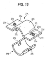
- Fig. 16 is a view of outer ring split parts according to eleventh embodiment.
- a fitting protrusion 27j that circumferentially protrudes is formed at both circumferential ends of an arc portion 27c of an upper outer ring split part 27A, by cutting a portion of an attachment portion 27d and bending it.
- a fitting groove 27k that is fitted to the fitting protrusion 27j is formed at both circumferential ends of a lower outer ring split part 27B.
- a reference numeral 27m denotes the holes formed through the attachment portions 27d formed by cutting and bending the fitting protrusions 27j. Further, in the embodiment shown in Fig.
- screw insertion holes 27e that have cylindrical protrusions 27n on the attachment portions 27d are formed in the attachment portions 27d of the upper outer ring split part 27A, by burring.
- the attachment portions 27d are integrally formed with the upper outer ring split part 27A and the lower outer ring split part 27B is the same as in the ninth embodiment, in that it is formed in a substantial half-circular arc shape without an attachment portion.
- Fig. 17A is a longitudinal cross-sectional view of outer ring split parts according to twelfth embodiment and Fig. 17B is a cross-sectional view taken along the line b-b of Fig. 17A.
- an inner rib 270 that protrudes axially inward is formed at both axial ends of an arc portion 27c of an upper outer ring split part 27A.
- the inner ribs 270 axially restrict the cage 26 with the rollers 25 held. Accordingly, the inner ribs 270 extend at least to the axial position where the cage 26 is located. Further, the inner ribs 270 are formed at least at the arc portion 27c in the upper outer ring split part 27A and may not be formed at the attachment portions 27d.
- Fig. 18 is a longitudinal cross-sectional side view of a split roller bearing device including the outer ring split parts of Fig. 17.
- a larger diameter portion 31b is formed in the shaft body 31, and a roller bearing 24 including a cage 26 with rollers 25 held and outer ring split parts 27A, 27B are mounted around the larger diameter portion 31b, of which outer circumference functions as the inner ring of the roller bearing 24.
- inner ribs 270 are formed at both axial sides of the upper outer ring split part 27A and inner ribs 27p the same as the inner ribs 270 are also formed at both axial sides of the lower outer ring split part 27B.
- attachment portions 27d are formed at an upper outer ring split part 27A, and not only the upper outer ring split part 27A, but a lower outer ring split part 27B are fixed to a housing 23, by fixedly attach the attachment portions 27d to the housing 23. It is the same as the ninth embodiment that a roller bearing 24 including the outer ring split parts 27A, 27B is fixedly mounted on the housing 23.
- a roller bearing 24 can be mounted around a portion having the same diameter as other portion of a shaft body 31 or a larger diameter portion 31b of the shaft body 31, without mounting the roller bearing 24 around an outer circumference of a smaller diameter portion 31a of the shaft body 31.
- the inner ring has a high precision by grinding or polishing the outer circumference of the larger diameter portion 31b.
- the inner circumference of the arc-shaped recess 23a of the housing 23 may be used as the outer ring, without the lower outer ring split part 27B of a steel plate. According to this configuration, the inner circumference of the arc-shaped recess 23a of the housing 23 turns out one of the outer ring split parts.
Landscapes
- Engineering & Computer Science (AREA)
- General Engineering & Computer Science (AREA)
- Mechanical Engineering (AREA)
- Rolling Contact Bearings (AREA)
Applications Claiming Priority (2)
| Application Number | Priority Date | Filing Date | Title |
|---|---|---|---|
| JP2006076175A JP2007247875A (ja) | 2006-03-20 | 2006-03-20 | 分割型ころ軸受装置 |
| JP2006076176A JP2007247876A (ja) | 2006-03-20 | 2006-03-20 | 分割型ころ軸受装置 |
Publications (1)
| Publication Number | Publication Date |
|---|---|
| EP1837537A2 true EP1837537A2 (de) | 2007-09-26 |
Family
ID=38255006
Family Applications (1)
| Application Number | Title | Priority Date | Filing Date |
|---|---|---|---|
| EP07005700A Withdrawn EP1837537A2 (de) | 2006-03-20 | 2007-03-20 | Kugelschalenlagervorrichtung |
Country Status (2)
| Country | Link |
|---|---|
| US (1) | US20070223854A1 (de) |
| EP (1) | EP1837537A2 (de) |
Cited By (3)
| Publication number | Priority date | Publication date | Assignee | Title |
|---|---|---|---|---|
| WO2009045983A1 (en) * | 2007-10-03 | 2009-04-09 | The Timken Company | Positioning means for camshaft roller bearing |
| EP2899376A1 (de) * | 2014-01-27 | 2015-07-29 | Taiho Kogyo Co., Ltd | Lagerelement für Ventiltrieb |
| DE102020200684A1 (de) | 2020-01-22 | 2021-07-22 | Thyssenkrupp Ag | Wälzlagerring mit mindestens einer Wälzkörperlaufbahn und Wälzlager |
Families Citing this family (10)
| Publication number | Priority date | Publication date | Assignee | Title |
|---|---|---|---|---|
| WO2009028678A1 (ja) * | 2007-08-31 | 2009-03-05 | Jtekt Corporation | 軸受構造及びその製造方法 |
| US8136998B2 (en) * | 2007-12-13 | 2012-03-20 | Jtekt Corporation | Bearing apparatus |
| DE102010028581A1 (de) * | 2010-05-05 | 2011-11-10 | Robert Bosch Gmbh | Exzenterlager |
| JP5962270B2 (ja) * | 2012-07-09 | 2016-08-03 | 日本精工株式会社 | ラジアルころ軸受用保持器 |
| DE102013018582B4 (de) * | 2012-12-07 | 2021-11-25 | Heidelberger Druckmaschinen Intellectual Property Ag & Co. Kg | Drucktechnische Maschine und Lagerung für eine Welle einer drucktechnischen Maschine |
| CN104141696A (zh) * | 2014-07-25 | 2014-11-12 | 朱彩玲 | 一种平面轴承固定块 |
| US20160069392A1 (en) * | 2014-09-10 | 2016-03-10 | Schaeffler Technologies AG & Co. KG | Radial bearing with variable lubrication flow restriction |
| US9528552B2 (en) * | 2015-01-16 | 2016-12-27 | Hamilton Sundstrand Corporation | Roller bearing outer race for hydraulic unit |
| DE102016203594A1 (de) * | 2016-03-04 | 2017-09-07 | Mahle International Gmbh | Vormontierte Lagerbaugruppe |
| DE102016211694B3 (de) * | 2016-06-29 | 2017-10-05 | Ford Global Technologies, Llc | Getriebeeinheit für ein Kraftfahrzeug |
-
2007
- 2007-03-16 US US11/723,176 patent/US20070223854A1/en not_active Abandoned
- 2007-03-20 EP EP07005700A patent/EP1837537A2/de not_active Withdrawn
Cited By (9)
| Publication number | Priority date | Publication date | Assignee | Title |
|---|---|---|---|---|
| WO2009045983A1 (en) * | 2007-10-03 | 2009-04-09 | The Timken Company | Positioning means for camshaft roller bearing |
| CN101918725B (zh) * | 2007-10-03 | 2013-03-27 | 美国光洋轴承有限责任公司 | 凸轮轴辊子轴承定位装置 |
| US8568038B2 (en) | 2007-10-03 | 2013-10-29 | Koyo Bearings Usa Llc | Positioning means for camshaft roller bearing |
| KR101429324B1 (ko) * | 2007-10-03 | 2014-08-11 | 코요 베어링즈 유에스에이, 엘엘씨 | 캠샤프트 롤러 베어링을 위한 위치설정 수단 |
| US9062709B2 (en) | 2007-10-03 | 2015-06-23 | Koyo Bearings North America Llc | Positioning means for camshaft roller bearing |
| EP2899376A1 (de) * | 2014-01-27 | 2015-07-29 | Taiho Kogyo Co., Ltd | Lagerelement für Ventiltrieb |
| US9371746B2 (en) | 2014-01-27 | 2016-06-21 | Taiho Kogyo Co., Ltd. | Bearing member for valve gear |
| DE102020200684A1 (de) | 2020-01-22 | 2021-07-22 | Thyssenkrupp Ag | Wälzlagerring mit mindestens einer Wälzkörperlaufbahn und Wälzlager |
| DE102020200684B4 (de) | 2020-01-22 | 2024-01-04 | Thyssenkrupp Ag | Großwälzlager mit einem Wälzlagerring mit mindestens einer Wälzkörperlaufbahn |
Also Published As
| Publication number | Publication date |
|---|---|
| US20070223854A1 (en) | 2007-09-27 |
Similar Documents
| Publication | Publication Date | Title |
|---|---|---|
| EP1837537A2 (de) | Kugelschalenlagervorrichtung | |
| CN102089539B (zh) | 用于轴承的波形膨胀套筒 | |
| US9512881B2 (en) | Roller bearing and shaft support structure | |
| EP2278182B1 (de) | Geteilter Außenring, geteiltes Wälzlager und Montageanordnung eines geteilten Wälzlagers | |
| US8464680B2 (en) | Disengageable module for a system for transmitting a starting torque to an internal combustion engine | |
| JP4790341B2 (ja) | 針状ころ軸受および軸受構造 | |
| US20100147104A1 (en) | Cam Shaft Assembly and Assembly Method Thereof | |
| EP2497914A1 (de) | Nockenwellenvorrichtung | |
| US7707983B2 (en) | Rolling bearing, cam shaft assembly and cam shaft supporting apparatus | |
| JP5762698B2 (ja) | 分割型ニードル軸受及び軸受装置 | |
| CN101137853B (zh) | 滚针轴承 | |
| EP1862695A1 (de) | Wellenvorrichtung | |
| JP2007247875A (ja) | 分割型ころ軸受装置 | |
| CN100572760C (zh) | 凸轮轴装置 | |
| JP5050954B2 (ja) | カムシャフトの軸受装置 | |
| EP1878881A1 (de) | Nockenwellenvorrichtung und verfahren zur montage der nockenwellenvorrichtung | |
| JP2019183888A (ja) | 回転軸の軸受支持構造 | |
| JP2006226184A (ja) | カムシャフト装置及びその組立方法 | |
| JP4480636B2 (ja) | 針状ころ軸受 | |
| JPH08277842A (ja) | 玉軸受用保持器 | |
| US20120060782A1 (en) | Rocker arm assembly with integrated support pin anti-inversion feature | |
| JP2007024207A (ja) | 針状ころ軸受 | |
| JP2007270628A (ja) | 燃料ポンプ用ころ軸受 | |
| JP2010117008A (ja) | 転がり軸受の取付構造及び方法 | |
| JP4893997B2 (ja) | 一方向クラッチ |
Legal Events
| Date | Code | Title | Description |
|---|---|---|---|
| PUAI | Public reference made under article 153(3) epc to a published international application that has entered the european phase |
Free format text: ORIGINAL CODE: 0009012 |
|
| AK | Designated contracting states |
Kind code of ref document: A2 Designated state(s): AT BE BG CH CY CZ DE DK EE ES FI FR GB GR HU IE IS IT LI LT LU LV MC MT NL PL PT RO SE SI SK TR |
|
| AX | Request for extension of the european patent |
Extension state: AL BA HR MK YU |
|
| STAA | Information on the status of an ep patent application or granted ep patent |
Free format text: STATUS: THE APPLICATION HAS BEEN WITHDRAWN |
|
| 18W | Application withdrawn |
Effective date: 20091123 |