EP1837602A2 - Dispositif doté d'une porte d'appareil de cuisson, d'une unité d'actionnement et d'un élément de verrouillage - Google Patents
Dispositif doté d'une porte d'appareil de cuisson, d'une unité d'actionnement et d'un élément de verrouillage Download PDFInfo
- Publication number
- EP1837602A2 EP1837602A2 EP07101237A EP07101237A EP1837602A2 EP 1837602 A2 EP1837602 A2 EP 1837602A2 EP 07101237 A EP07101237 A EP 07101237A EP 07101237 A EP07101237 A EP 07101237A EP 1837602 A2 EP1837602 A2 EP 1837602A2
- Authority
- EP
- European Patent Office
- Prior art keywords
- cooking appliance
- locking element
- appliance door
- locking
- actuator unit
- Prior art date
- Legal status (The legal status is an assumption and is not a legal conclusion. Google has not performed a legal analysis and makes no representation as to the accuracy of the status listed.)
- Granted
Links
Images


Classifications
-
- F—MECHANICAL ENGINEERING; LIGHTING; HEATING; WEAPONS; BLASTING
- F24—HEATING; RANGES; VENTILATING
- F24C—DOMESTIC STOVES OR RANGES ; DETAILS OF DOMESTIC STOVES OR RANGES, OF GENERAL APPLICATION
- F24C15/00—Details
- F24C15/02—Doors specially adapted for stoves or ranges
- F24C15/022—Latches
-
- E—FIXED CONSTRUCTIONS
- E05—LOCKS; KEYS; WINDOW OR DOOR FITTINGS; SAFES
- E05B—LOCKS; ACCESSORIES THEREFOR; HANDCUFFS
- E05B47/00—Operating or controlling locks or other fastening devices by electric or magnetic means
- E05B47/02—Movement of the bolt by electromagnetic means; Adaptation of locks, latches, or parts thereof, for movement of the bolt by electromagnetic means
- E05B47/023—Movement of the bolt by electromagnetic means; Adaptation of locks, latches, or parts thereof, for movement of the bolt by electromagnetic means the bolt moving pivotally or rotatively
-
- H—ELECTRICITY
- H05—ELECTRIC TECHNIQUES NOT OTHERWISE PROVIDED FOR
- H05B—ELECTRIC HEATING; ELECTRIC LIGHT SOURCES NOT OTHERWISE PROVIDED FOR; CIRCUIT ARRANGEMENTS FOR ELECTRIC LIGHT SOURCES, IN GENERAL
- H05B6/00—Heating by electric, magnetic or electromagnetic fields
- H05B6/64—Heating using microwaves
- H05B6/6414—Aspects relating to the door of the microwave heating apparatus
- H05B6/6417—Door interlocks of the microwave heating apparatus and related circuits
-
- E—FIXED CONSTRUCTIONS
- E05—LOCKS; KEYS; WINDOW OR DOOR FITTINGS; SAFES
- E05B—LOCKS; ACCESSORIES THEREFOR; HANDCUFFS
- E05B17/00—Accessories in connection with locks
- E05B17/0054—Fraction or shear lines; Slip-clutches, resilient parts or the like for preventing damage when forced or slammed
- E05B17/0058—Fraction or shear lines; Slip-clutches, resilient parts or the like for preventing damage when forced or slammed with non-destructive disengagement
-
- E—FIXED CONSTRUCTIONS
- E05—LOCKS; KEYS; WINDOW OR DOOR FITTINGS; SAFES
- E05B—LOCKS; ACCESSORIES THEREFOR; HANDCUFFS
- E05B47/00—Operating or controlling locks or other fastening devices by electric or magnetic means
- E05B2047/0048—Circuits, feeding, monitoring
- E05B2047/0067—Monitoring
- E05B2047/0068—Door closed
-
- E—FIXED CONSTRUCTIONS
- E05—LOCKS; KEYS; WINDOW OR DOOR FITTINGS; SAFES
- E05B—LOCKS; ACCESSORIES THEREFOR; HANDCUFFS
- E05B47/00—Operating or controlling locks or other fastening devices by electric or magnetic means
- E05B2047/0048—Circuits, feeding, monitoring
- E05B2047/0067—Monitoring
- E05B2047/0069—Monitoring bolt position
-
- Y—GENERAL TAGGING OF NEW TECHNOLOGICAL DEVELOPMENTS; GENERAL TAGGING OF CROSS-SECTIONAL TECHNOLOGIES SPANNING OVER SEVERAL SECTIONS OF THE IPC; TECHNICAL SUBJECTS COVERED BY FORMER USPC CROSS-REFERENCE ART COLLECTIONS [XRACs] AND DIGESTS
- Y10—TECHNICAL SUBJECTS COVERED BY FORMER USPC
- Y10S—TECHNICAL SUBJECTS COVERED BY FORMER USPC CROSS-REFERENCE ART COLLECTIONS [XRACs] AND DIGESTS
- Y10S292/00—Closure fasteners
- Y10S292/69—Washing machine or stove closure latch
-
- Y—GENERAL TAGGING OF NEW TECHNOLOGICAL DEVELOPMENTS; GENERAL TAGGING OF CROSS-SECTIONAL TECHNOLOGIES SPANNING OVER SEVERAL SECTIONS OF THE IPC; TECHNICAL SUBJECTS COVERED BY FORMER USPC CROSS-REFERENCE ART COLLECTIONS [XRACs] AND DIGESTS
- Y10—TECHNICAL SUBJECTS COVERED BY FORMER USPC
- Y10T—TECHNICAL SUBJECTS COVERED BY FORMER US CLASSIFICATION
- Y10T292/00—Closure fasteners
- Y10T292/08—Bolts
- Y10T292/1043—Swinging
- Y10T292/1075—Operating means
- Y10T292/1083—Rigid
-
- Y—GENERAL TAGGING OF NEW TECHNOLOGICAL DEVELOPMENTS; GENERAL TAGGING OF CROSS-SECTIONAL TECHNOLOGIES SPANNING OVER SEVERAL SECTIONS OF THE IPC; TECHNICAL SUBJECTS COVERED BY FORMER USPC CROSS-REFERENCE ART COLLECTIONS [XRACs] AND DIGESTS
- Y10—TECHNICAL SUBJECTS COVERED BY FORMER USPC
- Y10T—TECHNICAL SUBJECTS COVERED BY FORMER US CLASSIFICATION
- Y10T292/00—Closure fasteners
- Y10T292/20—Clamps
- Y10T292/228—Portable
Definitions
- the invention relates to a device with a cooking appliance door, an actuator unit and a locking element according to the preamble of claim 1.
- From the DE 40 40 343 C2 is a device, namely a cooking appliance, with a cooking appliance door, an actuator unit and with a locking element for locking the Garellae known.
- the locking element is used in particular when performing a pyrolysis function.
- the actuator unit is provided for locking the cooking appliance door when the cooking appliance door is closed, bringing the locking element into engagement with a corresponding locking element or with a locking cup of the cooking appliance door.
- the invention is in particular the object of designing a generic device particularly space-saving and cost-effective.
- the object is achieved by a device having the features of claim 1. Further advantageous embodiments and modifications of the invention will become apparent from the dependent claims.
- the invention is based on a device having a cooking appliance door, an actuator unit and a locking element for locking the cooking appliance door, in particular when carrying out a pyrolysis function, the actuator unit being provided for locking the cooking appliance door with the cooking appliance door closed, the locking element with a corresponding locking element of the cooking appliance door to engage.
- the actuator unit can be designed in a manner which appears appropriate to a person skilled in the art, for example as a wax element, electric motor or solenoid, whose movement is converted into a rotational movement.
- the locking element run around a cooking appliance door closed at least substantially perpendicular to a door level of the cooking appliance door Rotary axis is rotatable.
- the installation space necessary for the realization of an axially displaceable locking element can be saved, and in particular a space of the locking element required in a front region of the cooking appliance can be utilized particularly well.
- a depth of the installation space to be used for the freedom of movement of the locking element can be limited at least essentially to the material thickness of the locking element.
- a decoupling of the actuator unit from the forces acting on the locking element can be realized in a simple manner. Overall, both the actuator unit and the locking element can be made more cost-effective compared to known devices of the generic type.
- a rotation axis whose angle to the door level is in a range between 70 ° and 110 °, preferably in a range between 80 ° and 100 °, so that a In any case, the component of a movement of the locking element in the door plane is greater than a component perpendicular thereto.
- the locking element has an at least substantially perpendicular to the axis of rotation extending locking hook.
- the actuator unit can be arranged at an almost arbitrary point of the cooking appliance, when the locking element comprises a rod which bridges a distance between the actuator unit and the locking hook. As a result, a space within the cooking appliance can be used particularly well.
- the actuator unit can be effectively shielded from acting on a front portion of the locking element locking forces when the rod is rotatably and axially fixedly mounted in a guide bearing on a cooking appliance body.
- the storage can be done for example via a groove in the rod or via an engaging in such a groove storage ring.
- the actuator unit can be arranged in a structurally simple manner away from a control panel and a control unit of the cooking appliance, if the distance between the actuator unit and the locking hook is at least 20 cm.
- the locking device according to the invention can be used in particular without significant structural changes in connection with known control panels or control electronics, since only a narrow opening for the passage of the rod is necessary.
- An inexpensive and structurally simple locking device can be realized in that the corresponding locking element of the cooking appliance door is formed as a recess in a lateral edge surface of the cooking appliance door.
- the cooking appliance door is pivotable about a pivot axis extending along a first edge and if the corresponding locking element is arranged on a side edge of the cooking appliance door opposite the first edge, it can be achieved that the locking element takes advantage of optimum leverage.
- the locking element and the corresponding locking element can be inexpensively designed for a lower locking force compared to an arrangement in the region of the pivot axis.
- the corresponding locking element has a stop surface for limiting a rotational movement of the locking element, it is possible to dispense with a limitation of the rotational movement in the mounting of the locking element. Furthermore, a defined, reproducible locking position can be ensured, which always reaches the locking element when the corresponding locking element is not dirty.
- a corresponding locking element adapted to the pivoting movement of the locking hook can be achieved in that the corresponding locking element of the cooking appliance door has at least one boundary surface which, when the cooking appliance door is closed, forms a section of a lateral surface which is axisymmetric with respect to the axis of rotation of the locking element.
- the corresponding locking element has the shape of a circle segment, in particular the shape of a quarter circle. Then Namely, a radial boundary surface of the corresponding locking element can be used as a stop surface.
- An overload of the actuator in a blockade of the locking element can be avoided if the locking element is connected via a torsion spring element with the actuator unit.
- the torsion spring element is formed by the rod between the actuator unit and the locking hook, costs can be saved and a diversity of components can be reduced.
- the device comprises at least one sensor element for detecting a position of the locking element
- the locking can be reliably ensured and a risk of burns for an operator can be reduced. Furthermore, from the fact that the locking element does not reach its locking position despite the corresponding activity of the actuator unit, contamination of the corresponding locking element in the cooking appliance door can be concluded. If this is the case, a control unit of the cooking appliance can block the pyrolysis function to avoid dangers and, if necessary, prompt the operator to clean the corresponding locking element.
- An incomplete locking can be excluded if the device comprises at least one further sensor element for detecting a position of the cooking appliance door in addition to the sensor element for detecting the position of the locking element.
- the further sensor element can be designed, for example, inexpensively and robustly as a reed switch.
- a universally usable locking device can be achieved if the locking element and the sensor element with respect to their installation position are interchangeable. It can be used in particular a holding device for such a sensor element for holding the locking element, whereby a constructive effort can be reduced.
- a holding device for such a sensor element for holding the locking element whereby a constructive effort can be reduced.
- the locking device and the sensor element can be ensured by the interchangeability of the locking device and the sensor element, that the locking element always at a respect the lever effect advantageous side of an upper or lower edge of the cooking appliance door is arranged.
- the actuator unit is intended to be arranged in a rear half of a cooking appliance comprising the cooking appliance door with respect to a cooking chamber opening that can be closed by the cooking appliance door, the generally very limited available installation space in the front half of the cooking appliance can advantageously be used for other purposes. Further advantages will become apparent from the following description of the figures.
- the figures show an embodiment of the invention.
- the figures, the description and the claims contain numerous features in combination which the skilled person will also consider individually and summarize to meaningful further combinations.
- FIG. 1 shows a cooking appliance designed as a household baking oven with a pyrolysis function with a cooking appliance door 10, an actuator unit 12 and a locking element 14 for locking the cooking appliance door 10.
- the locking element 14 serves to lock the cooking appliance door 10, in particular when carrying out the pyrolysis function, wherein the Actuator unit 12 is provided for locking the cooking appliance door 10 when the cooking appliance door 10 is closed, the locking element 14 with a corresponding locking element 15 or with a locking shell of Garaust 10 into engagement.
- the locking element 14 is rotatable about the axis of rotation 16 with the aid of the actuator unit 12, which extends horizontally above a cooking chamber when the cooking appliance door 10 is perpendicular to a door level and when the cooking appliance is set up.
- the locking element 14 comprises a rod 18 and a perpendicular to the axis of rotation 16 extending locking hook 20.
- the rod 18 bridges a distance of at least 20 cm between the actuator unit 12 and the locking hook 20.
- the locking hook 20 is perpendicular from the rod 18 from.
- the rod 18 is rotatably and axially fixedly mounted in a guide bearing 22 on a cooking appliance body of the cooking appliance.
- the guide bearing 22 shields all forces acting on the locking element 14 in the region of the locking hook 20 from the actuator unit 12 so that they can not be damaged by tugging on the cooking device door 10.
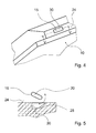
- the corresponding locking element 15 of the cooking appliance door 10 is formed as a shell-shaped recess or as a locking shell in a lateral edge surface 24 of the cooking appliance door 10 in a view perpendicular to the cooking appliance door 10 has the shape of a quarter circle ( Figure 5).
- the cooking appliance door 10 is pivotable about two hinges not explicitly shown here about a pivot axis 26 extending along a first, lower edge.
- the corresponding locking element 15 is arranged on an upper side edge of the cooking appliance door 10 opposite the first edge (FIG. 4).
- a further boundary surface 30 of the corresponding locking element 15 forms with closed cooking appliance door 10 a section of an axis of symmetry with respect to the axis of rotation 16 of the locking element 14, namely a section of a cylinder jacket surface.
- the locking element 14 with the locking hook rotates beyond the locking position defined by the stop surface 28 when the lock is activated, then the corresponding locking element 15 is not present in the locking position because e.g. the cooking appliance door 10 is not completely closed.
- the cooking appliance comprises a sensor element 34 for detecting a position of the locking element 14, by means of which a central control unit can detect whether the locking element 14 is in the locking position.
- the latter is a necessary condition for the locking of the cooking appliance door 10.
- the cooking appliance has another designed as a reed switch sensor element 36 for detecting a position of the cooking appliance door 10. This allows the control unit also detect a sufficient condition for the locking of the cooking appliance door 10. Only when the locking element 14 is in the locking position and at the same time the cooking appliance door 10 is fully closed, there is a positive fit and the cooking appliance door 10 can not be opened. Only when these conditions are met does the control unit start a pyrolysis process.
- the locking element 14 and the further sensor element 36 for detecting a position of the cooking appliance door 10 each engage through similar recesses 38, 40 in a front plate of a muffle 42 of the cooking appliance. Both units are therefore interchangeable with respect to their installation position.
- Actuator unit 12 itself is arranged above muffle 42 in a rear half of the cooking appliance with respect to a cooking chamber opening which can be closed by cooking appliance door 10.
- the space in the front half of the cooking appliance remains free for other assemblies that are directly operable via a control panel 44 of the cooking appliance and should therefore be placed in the immediate vicinity of the latter to form a compact assembly.
Landscapes
- Physics & Mathematics (AREA)
- Electromagnetism (AREA)
- Engineering & Computer Science (AREA)
- Chemical & Material Sciences (AREA)
- Combustion & Propulsion (AREA)
- Mechanical Engineering (AREA)
- General Engineering & Computer Science (AREA)
- Electric Ovens (AREA)
- Cookers (AREA)
- Furnace Housings, Linings, Walls, And Ceilings (AREA)
- Baking, Grill, Roasting (AREA)
Applications Claiming Priority (1)
| Application Number | Priority Date | Filing Date | Title |
|---|---|---|---|
| DE200610013519 DE102006013519A1 (de) | 2006-03-23 | 2006-03-23 | Vorrichtung mit einer Gargerätetür, einer Aktoreinheit und einem Verriegelungselement |
Publications (3)
| Publication Number | Publication Date |
|---|---|
| EP1837602A2 true EP1837602A2 (fr) | 2007-09-26 |
| EP1837602A3 EP1837602A3 (fr) | 2011-03-16 |
| EP1837602B1 EP1837602B1 (fr) | 2014-05-07 |
Family
ID=38226561
Family Applications (1)
| Application Number | Title | Priority Date | Filing Date |
|---|---|---|---|
| EP20070101237 Active EP1837602B1 (fr) | 2006-03-23 | 2007-01-26 | Dispositif doté d'une porte d'appareil de cuisson, d'une unité d'actionnement et d'un élément de verrouillage |
Country Status (3)
| Country | Link |
|---|---|
| US (1) | US7475921B2 (fr) |
| EP (1) | EP1837602B1 (fr) |
| DE (1) | DE102006013519A1 (fr) |
Cited By (2)
| Publication number | Priority date | Publication date | Assignee | Title |
|---|---|---|---|---|
| WO2018215022A1 (fr) * | 2017-05-22 | 2018-11-29 | Rahrbach Gmbh | Dispositif de fermeture électromécanique pour portes d'appareils |
| WO2020048687A1 (fr) * | 2018-09-06 | 2020-03-12 | Arcelik Anonim Sirketi | Dispositif de cuisson facile à utiliser |
Families Citing this family (7)
| Publication number | Priority date | Publication date | Assignee | Title |
|---|---|---|---|---|
| DE102009017246A1 (de) | 2008-04-11 | 2009-10-15 | Rahrbach Gmbh | Verschluss für Gerätetüren mit zusätzlichem Sperriegel |
| DE102009016812B4 (de) | 2008-04-11 | 2022-02-03 | Rahrbach Gmbh | Türverschluss für ein thermisches Gar- und/oder Backgerät |
| DE102009014233A1 (de) * | 2008-12-23 | 2010-06-24 | Convotherm Elektrogeräte GmbH | Verschluss für eine Tür eines Gargeräts, Gargerät und Verfahren zum Betreiben eines Gargerätes |
| DE102013001905A1 (de) | 2013-02-05 | 2014-08-21 | Küppersbusch Großküchentechnik GmbH & Co. KG | Gargerät, insbesondere zur Verwendung im Großküchenbereich |
| ITTO20130691A1 (it) * | 2013-08-13 | 2015-02-14 | Elbi Int Spa | Apparecchiatura per controllare la chiusura di una porta di un elettrodomestico, in particolare per una macchina lavatrice, quale una macchina lavastoviglie. |
| CN105737223B (zh) * | 2016-02-01 | 2017-12-19 | 广东美的厨房电器制造有限公司 | 带抽屉的厨房电器 |
| US11573009B2 (en) * | 2020-05-05 | 2023-02-07 | Whirlpool Corporation | Appliance latch assembly |
Family Cites Families (15)
| Publication number | Priority date | Publication date | Assignee | Title |
|---|---|---|---|---|
| US2123521A (en) * | 1936-05-01 | 1938-07-12 | Koppers Co Inc | Coke oven door operating mechanism |
| US2394784A (en) * | 1942-11-11 | 1946-02-12 | Detroit Steel Products Co | Closure construction |
| US2529009A (en) * | 1946-03-04 | 1950-11-07 | Hans L Foss | Barn door latch |
| US3011816A (en) * | 1960-09-19 | 1961-12-05 | Jervis Corp | Latch mechanism |
| GB1241558A (en) * | 1967-12-30 | 1971-08-04 | Simplex Electric Co Ltd | Improvements relating to self-cleaning electric ovens |
| US3507531A (en) * | 1968-08-30 | 1970-04-21 | Maytag Co | Adjustable door latch |
| US3893554A (en) * | 1974-06-07 | 1975-07-08 | Thomas D Wason | Torque limiting clutch |
| DE2528612A1 (de) * | 1974-07-23 | 1976-02-12 | Dietrich & Cie De | Sicherheitseinrichtung fuer die betaetigung von tueren an einbau- und herdbackoefen, o.dgl. mit pyrolytischer reinigung |
| FR2287659A2 (fr) * | 1974-10-09 | 1976-05-07 | Scholtes Ets Eugen | Four electrique de cuisson et dispositif de blocage de celui-ci |
| DE2949773A1 (de) * | 1979-12-11 | 1981-06-19 | Bosch-Siemens Hausgeräte GmbH, 7000 Stuttgart | Vorrichtung zur verriegelung einer backofentuer eines pyrolytisch selbstreinigenden backofens |
| US4374320A (en) * | 1981-05-18 | 1983-02-15 | White Consolidated Industries, Inc. | Motorized oven door latch and control circuit for same |
| DE4040343C2 (de) | 1990-12-17 | 1999-05-27 | Bosch Siemens Hausgeraete | Verriegelungsvorrichtung für die Tür eines Backofens |
| US5887916A (en) * | 1997-09-25 | 1999-03-30 | Kason Industries, Inc. | Safety door latch for pressurized ovens |
| EP1438473B1 (fr) * | 2001-10-04 | 2012-12-05 | The Hartwell Corporation | Pene dormant sensible a la pression |
| DE10309594B4 (de) * | 2003-03-05 | 2006-04-20 | Convotherm Elektrogeräte GmbH | Verschlusseinrichtung für die Tür von Großküchengeräten |
-
2006
- 2006-03-23 DE DE200610013519 patent/DE102006013519A1/de not_active Withdrawn
-
2007
- 2007-01-26 EP EP20070101237 patent/EP1837602B1/fr active Active
- 2007-03-21 US US11/726,470 patent/US7475921B2/en not_active Expired - Fee Related
Cited By (2)
| Publication number | Priority date | Publication date | Assignee | Title |
|---|---|---|---|---|
| WO2018215022A1 (fr) * | 2017-05-22 | 2018-11-29 | Rahrbach Gmbh | Dispositif de fermeture électromécanique pour portes d'appareils |
| WO2020048687A1 (fr) * | 2018-09-06 | 2020-03-12 | Arcelik Anonim Sirketi | Dispositif de cuisson facile à utiliser |
Also Published As
| Publication number | Publication date |
|---|---|
| EP1837602B1 (fr) | 2014-05-07 |
| DE102006013519A1 (de) | 2007-10-11 |
| EP1837602A3 (fr) | 2011-03-16 |
| US20070236022A1 (en) | 2007-10-11 |
| US7475921B2 (en) | 2009-01-13 |
Similar Documents
| Publication | Publication Date | Title |
|---|---|---|
| EP1837602B1 (fr) | Dispositif doté d'une porte d'appareil de cuisson, d'une unité d'actionnement et d'un élément de verrouillage | |
| EP2147178B1 (fr) | Agencement de charnière | |
| EP3665351B1 (fr) | Charnière pour portes ou parois amovibles d'armoire en tôle | |
| DE102015109093B3 (de) | Kohlegrill mit höhenverstellbarem Kohlerost | |
| EP3045639A1 (fr) | Charniere d'appareil menager et procede de fonctionnement d'une telle charniere | |
| EP2929764B1 (fr) | Boîte munie d'une articulation | |
| DE102008011650A1 (de) | Haushaltsgerätetür und Verfahren zum Bedienen der Haushaltsgerätetür | |
| DE102011101284A1 (de) | Verriegelungsvorrichtung | |
| DE102004007390B4 (de) | Verriegelungseinheit für ein bewegliches Schließelement | |
| DE60315253T2 (de) | Kofferraumdeckel für ein cabriofahrzeug mit faltverdeck | |
| DE102012112084A1 (de) | Türschließer mit verstellbarer Federeinheit | |
| DE102008024584A1 (de) | Tankklappenverriegelungseinrichtung und Anordnung einer Tankklappenverriegelungseinrichtung in einer Tankmulde eines Kraftfahrzeugs | |
| DE102006032700B3 (de) | Anbindungsvorrichtung für eine Halteeinrichtung eines Deckels eines öffnungsfähigen Fahrzeugdaches | |
| DE102016122015B3 (de) | Türverschluss für ein Gargerät | |
| WO2004081324A1 (fr) | Dispositif de fermeture pour portes d'appareils de cuisines industrielles | |
| DE102023118984A1 (de) | Kombiniertes Sicherungselement zur Verwendung mit einem feststehenden Bauteil und einem beweglichen Bauteil | |
| DE102014007841A1 (de) | Dachfenster sowie Verfahren zum Montieren eines Dachfensters | |
| DE202004004619U1 (de) | Mechanische Schließvorrichtung für Elektrosteckergehäuse | |
| EP0900904A2 (fr) | Charnière pour couvertures de conteneur | |
| DE202008007778U1 (de) | Kraftfahrzeugtürscharnier | |
| EP3430966B1 (fr) | Lave-vaisselle électroménager | |
| DE202018101859U1 (de) | Vorrichtung zum Fixieren eines Batterietrogs eines Flurförderzeugs | |
| DE2946259A1 (de) | Schwenkhalterung eines befestigungskopfes, insbesondere fuer eine an einer kraftfahrzeug-heckklappe angreifende, dem gewichtsausgleich dienende gasfeder | |
| DE102008029320B3 (de) | Klemmbeschlag, Anschlagtür und Gargerät | |
| DE102005014924B4 (de) | Gelenkscharnier, insbesondere 4-Gelenkscharnier |
Legal Events
| Date | Code | Title | Description |
|---|---|---|---|
| PUAI | Public reference made under article 153(3) epc to a published international application that has entered the european phase |
Free format text: ORIGINAL CODE: 0009012 |
|
| AK | Designated contracting states |
Kind code of ref document: A2 Designated state(s): AT BE BG CH CY CZ DE DK EE ES FI FR GB GR HU IE IS IT LI LT LU LV MC NL PL PT RO SE SI SK TR |
|
| AX | Request for extension of the european patent |
Extension state: AL BA HR MK RS YU |
|
| PUAL | Search report despatched |
Free format text: ORIGINAL CODE: 0009013 |
|
| AK | Designated contracting states |
Kind code of ref document: A3 Designated state(s): AT BE BG CH CY CZ DE DK EE ES FI FR GB GR HU IE IS IT LI LT LU LV MC NL PL PT RO SE SI SK TR |
|
| AX | Request for extension of the european patent |
Extension state: AL BA HR MK RS |
|
| 17P | Request for examination filed |
Effective date: 20110916 |
|
| AKX | Designation fees paid |
Designated state(s): AT BE BG CH CY CZ DE DK EE ES FI FR GB GR HU IE IS IT LI LT LU LV MC NL PL PT RO SE SI SK TR |
|
| 17Q | First examination report despatched |
Effective date: 20130404 |
|
| RIC1 | Information provided on ipc code assigned before grant |
Ipc: F24C 15/02 20060101AFI20131105BHEP |
|
| GRAP | Despatch of communication of intention to grant a patent |
Free format text: ORIGINAL CODE: EPIDOSNIGR1 |
|
| INTG | Intention to grant announced |
Effective date: 20131216 |
|
| GRAS | Grant fee paid |
Free format text: ORIGINAL CODE: EPIDOSNIGR3 |
|
| GRAA | (expected) grant |
Free format text: ORIGINAL CODE: 0009210 |
|
| AK | Designated contracting states |
Kind code of ref document: B1 Designated state(s): AT BE BG CH CY CZ DE DK EE ES FI FR GB GR HU IE IS IT LI LT LU LV MC NL PL PT RO SE SI SK TR |
|
| REG | Reference to a national code |
Ref country code: GB Ref legal event code: FG4D Free format text: NOT ENGLISH |
|
| REG | Reference to a national code |
Ref country code: AT Ref legal event code: REF Ref document number: 666996 Country of ref document: AT Kind code of ref document: T Effective date: 20140515 |
|
| REG | Reference to a national code |
Ref country code: IE Ref legal event code: FG4D Free format text: LANGUAGE OF EP DOCUMENT: GERMAN |
|
| REG | Reference to a national code |
Ref country code: DE Ref legal event code: R096 Ref document number: 502007013061 Country of ref document: DE Effective date: 20140618 |
|
| REG | Reference to a national code |
Ref country code: NL Ref legal event code: VDEP Effective date: 20140507 |
|
| REG | Reference to a national code |
Ref country code: LT Ref legal event code: MG4D |
|
| PG25 | Lapsed in a contracting state [announced via postgrant information from national office to epo] |
Ref country code: LT Free format text: LAPSE BECAUSE OF FAILURE TO SUBMIT A TRANSLATION OF THE DESCRIPTION OR TO PAY THE FEE WITHIN THE PRESCRIBED TIME-LIMIT Effective date: 20140507 Ref country code: CY Free format text: LAPSE BECAUSE OF FAILURE TO SUBMIT A TRANSLATION OF THE DESCRIPTION OR TO PAY THE FEE WITHIN THE PRESCRIBED TIME-LIMIT Effective date: 20140507 Ref country code: IS Free format text: LAPSE BECAUSE OF FAILURE TO SUBMIT A TRANSLATION OF THE DESCRIPTION OR TO PAY THE FEE WITHIN THE PRESCRIBED TIME-LIMIT Effective date: 20140907 Ref country code: GR Free format text: LAPSE BECAUSE OF FAILURE TO SUBMIT A TRANSLATION OF THE DESCRIPTION OR TO PAY THE FEE WITHIN THE PRESCRIBED TIME-LIMIT Effective date: 20140808 Ref country code: FI Free format text: LAPSE BECAUSE OF FAILURE TO SUBMIT A TRANSLATION OF THE DESCRIPTION OR TO PAY THE FEE WITHIN THE PRESCRIBED TIME-LIMIT Effective date: 20140507 |
|
| PG25 | Lapsed in a contracting state [announced via postgrant information from national office to epo] |
Ref country code: LV Free format text: LAPSE BECAUSE OF FAILURE TO SUBMIT A TRANSLATION OF THE DESCRIPTION OR TO PAY THE FEE WITHIN THE PRESCRIBED TIME-LIMIT Effective date: 20140507 Ref country code: SE Free format text: LAPSE BECAUSE OF FAILURE TO SUBMIT A TRANSLATION OF THE DESCRIPTION OR TO PAY THE FEE WITHIN THE PRESCRIBED TIME-LIMIT Effective date: 20140507 Ref country code: PL Free format text: LAPSE BECAUSE OF FAILURE TO SUBMIT A TRANSLATION OF THE DESCRIPTION OR TO PAY THE FEE WITHIN THE PRESCRIBED TIME-LIMIT Effective date: 20140507 Ref country code: ES Free format text: LAPSE BECAUSE OF FAILURE TO SUBMIT A TRANSLATION OF THE DESCRIPTION OR TO PAY THE FEE WITHIN THE PRESCRIBED TIME-LIMIT Effective date: 20140507 |
|
| PG25 | Lapsed in a contracting state [announced via postgrant information from national office to epo] |
Ref country code: PT Free format text: LAPSE BECAUSE OF FAILURE TO SUBMIT A TRANSLATION OF THE DESCRIPTION OR TO PAY THE FEE WITHIN THE PRESCRIBED TIME-LIMIT Effective date: 20140908 |
|
| PG25 | Lapsed in a contracting state [announced via postgrant information from national office to epo] |
Ref country code: RO Free format text: LAPSE BECAUSE OF FAILURE TO SUBMIT A TRANSLATION OF THE DESCRIPTION OR TO PAY THE FEE WITHIN THE PRESCRIBED TIME-LIMIT Effective date: 20140507 Ref country code: SK Free format text: LAPSE BECAUSE OF FAILURE TO SUBMIT A TRANSLATION OF THE DESCRIPTION OR TO PAY THE FEE WITHIN THE PRESCRIBED TIME-LIMIT Effective date: 20140507 Ref country code: CZ Free format text: LAPSE BECAUSE OF FAILURE TO SUBMIT A TRANSLATION OF THE DESCRIPTION OR TO PAY THE FEE WITHIN THE PRESCRIBED TIME-LIMIT Effective date: 20140507 Ref country code: DK Free format text: LAPSE BECAUSE OF FAILURE TO SUBMIT A TRANSLATION OF THE DESCRIPTION OR TO PAY THE FEE WITHIN THE PRESCRIBED TIME-LIMIT Effective date: 20140507 Ref country code: EE Free format text: LAPSE BECAUSE OF FAILURE TO SUBMIT A TRANSLATION OF THE DESCRIPTION OR TO PAY THE FEE WITHIN THE PRESCRIBED TIME-LIMIT Effective date: 20140507 |
|
| REG | Reference to a national code |
Ref country code: DE Ref legal event code: R097 Ref document number: 502007013061 Country of ref document: DE |
|
| PG25 | Lapsed in a contracting state [announced via postgrant information from national office to epo] |
Ref country code: NL Free format text: LAPSE BECAUSE OF FAILURE TO SUBMIT A TRANSLATION OF THE DESCRIPTION OR TO PAY THE FEE WITHIN THE PRESCRIBED TIME-LIMIT Effective date: 20140507 |
|
| REG | Reference to a national code |
Ref country code: CH Ref legal event code: PFA Owner name: BSH HAUSGERAETE GMBH, DE Free format text: FORMER OWNER: BSH BOSCH UND SIEMENS HAUSGERAETE GMBH, DE |
|
| PLBE | No opposition filed within time limit |
Free format text: ORIGINAL CODE: 0009261 |
|
| STAA | Information on the status of an ep patent application or granted ep patent |
Free format text: STATUS: NO OPPOSITION FILED WITHIN TIME LIMIT |
|
| RAP2 | Party data changed (patent owner data changed or rights of a patent transferred) |
Owner name: BSH HAUSGERAETE GMBH |
|
| 26N | No opposition filed |
Effective date: 20150210 |
|
| PG25 | Lapsed in a contracting state [announced via postgrant information from national office to epo] |
Ref country code: IT Free format text: LAPSE BECAUSE OF FAILURE TO SUBMIT A TRANSLATION OF THE DESCRIPTION OR TO PAY THE FEE WITHIN THE PRESCRIBED TIME-LIMIT Effective date: 20140507 |
|
| REG | Reference to a national code |
Ref country code: DE Ref legal event code: R081 Ref document number: 502007013061 Country of ref document: DE Owner name: BSH HAUSGERAETE GMBH, DE Free format text: FORMER OWNER: BSH BOSCH UND SIEMENS HAUSGERAETE GMBH, 81739 MUENCHEN, DE Effective date: 20140509 Ref country code: DE Ref legal event code: R081 Ref document number: 502007013061 Country of ref document: DE Owner name: BSH HAUSGERAETE GMBH, DE Free format text: FORMER OWNER: BSH BOSCH UND SIEMENS HAUSGERAETE GMBH, 81739 MUENCHEN, DE Effective date: 20150407 |
|
| REG | Reference to a national code |
Ref country code: DE Ref legal event code: R097 Ref document number: 502007013061 Country of ref document: DE Effective date: 20150210 |
|
| PG25 | Lapsed in a contracting state [announced via postgrant information from national office to epo] |
Ref country code: BE Free format text: LAPSE BECAUSE OF NON-PAYMENT OF DUE FEES Effective date: 20150131 |
|
| PG25 | Lapsed in a contracting state [announced via postgrant information from national office to epo] |
Ref country code: SI Free format text: LAPSE BECAUSE OF FAILURE TO SUBMIT A TRANSLATION OF THE DESCRIPTION OR TO PAY THE FEE WITHIN THE PRESCRIBED TIME-LIMIT Effective date: 20140507 |
|
| REG | Reference to a national code |
Ref country code: CH Ref legal event code: PL |
|
| PG25 | Lapsed in a contracting state [announced via postgrant information from national office to epo] |
Ref country code: LU Free format text: LAPSE BECAUSE OF FAILURE TO SUBMIT A TRANSLATION OF THE DESCRIPTION OR TO PAY THE FEE WITHIN THE PRESCRIBED TIME-LIMIT Effective date: 20150126 |
|
| GBPC | Gb: european patent ceased through non-payment of renewal fee |
Effective date: 20150126 |
|
| PG25 | Lapsed in a contracting state [announced via postgrant information from national office to epo] |
Ref country code: MC Free format text: LAPSE BECAUSE OF FAILURE TO SUBMIT A TRANSLATION OF THE DESCRIPTION OR TO PAY THE FEE WITHIN THE PRESCRIBED TIME-LIMIT Effective date: 20140507 |
|
| PG25 | Lapsed in a contracting state [announced via postgrant information from national office to epo] |
Ref country code: GB Free format text: LAPSE BECAUSE OF NON-PAYMENT OF DUE FEES Effective date: 20150126 Ref country code: LI Free format text: LAPSE BECAUSE OF NON-PAYMENT OF DUE FEES Effective date: 20150131 Ref country code: CH Free format text: LAPSE BECAUSE OF NON-PAYMENT OF DUE FEES Effective date: 20150131 |
|
| REG | Reference to a national code |
Ref country code: FR Ref legal event code: ST Effective date: 20150930 |
|
| REG | Reference to a national code |
Ref country code: IE Ref legal event code: MM4A |
|
| PG25 | Lapsed in a contracting state [announced via postgrant information from national office to epo] |
Ref country code: FR Free format text: LAPSE BECAUSE OF NON-PAYMENT OF DUE FEES Effective date: 20150202 |
|
| PG25 | Lapsed in a contracting state [announced via postgrant information from national office to epo] |
Ref country code: IE Free format text: LAPSE BECAUSE OF NON-PAYMENT OF DUE FEES Effective date: 20150126 |
|
| REG | Reference to a national code |
Ref country code: AT Ref legal event code: MM01 Ref document number: 666996 Country of ref document: AT Kind code of ref document: T Effective date: 20150126 |
|
| PG25 | Lapsed in a contracting state [announced via postgrant information from national office to epo] |
Ref country code: AT Free format text: LAPSE BECAUSE OF NON-PAYMENT OF DUE FEES Effective date: 20150126 |
|
| PG25 | Lapsed in a contracting state [announced via postgrant information from national office to epo] |
Ref country code: HU Free format text: LAPSE BECAUSE OF FAILURE TO SUBMIT A TRANSLATION OF THE DESCRIPTION OR TO PAY THE FEE WITHIN THE PRESCRIBED TIME-LIMIT; INVALID AB INITIO Effective date: 20070126 Ref country code: BG Free format text: LAPSE BECAUSE OF FAILURE TO SUBMIT A TRANSLATION OF THE DESCRIPTION OR TO PAY THE FEE WITHIN THE PRESCRIBED TIME-LIMIT Effective date: 20140507 |
|
| REG | Reference to a national code |
Ref country code: DE Ref legal event code: R084 Ref document number: 502007013061 Country of ref document: DE |
|
| PGFP | Annual fee paid to national office [announced via postgrant information from national office to epo] |
Ref country code: DE Payment date: 20260131 Year of fee payment: 20 |