EP1837638A1 - Drucksensor - Google Patents
Drucksensor Download PDFInfo
- Publication number
- EP1837638A1 EP1837638A1 EP06111452A EP06111452A EP1837638A1 EP 1837638 A1 EP1837638 A1 EP 1837638A1 EP 06111452 A EP06111452 A EP 06111452A EP 06111452 A EP06111452 A EP 06111452A EP 1837638 A1 EP1837638 A1 EP 1837638A1
- Authority
- EP
- European Patent Office
- Prior art keywords
- pressure
- film
- pressure sensor
- sensor according
- piezoelectric
- Prior art date
- Legal status (The legal status is an assumption and is not a legal conclusion. Google has not performed a legal analysis and makes no representation as to the accuracy of the status listed.)
- Granted
Links
- 239000000758 substrate Substances 0.000 claims abstract description 31
- 238000003780 insertion Methods 0.000 claims abstract description 24
- 230000037431 insertion Effects 0.000 claims abstract description 24
- 238000005259 measurement Methods 0.000 claims abstract description 12
- 238000010897 surface acoustic wave method Methods 0.000 claims description 14
- 238000012545 processing Methods 0.000 claims description 10
- 230000008859 change Effects 0.000 claims description 6
- 230000001419 dependent effect Effects 0.000 claims description 4
- 238000012623 in vivo measurement Methods 0.000 claims description 4
- XUIMIQQOPSSXEZ-UHFFFAOYSA-N Silicon Chemical compound [Si] XUIMIQQOPSSXEZ-UHFFFAOYSA-N 0.000 claims description 3
- 238000009529 body temperature measurement Methods 0.000 claims description 3
- 229910052710 silicon Inorganic materials 0.000 claims description 3
- 239000010703 silicon Substances 0.000 claims description 3
- 235000019687 Lamb Nutrition 0.000 claims description 2
- 229910002113 barium titanate Inorganic materials 0.000 claims description 2
- 239000010408 film Substances 0.000 description 49
- 239000000463 material Substances 0.000 description 7
- 238000006073 displacement reaction Methods 0.000 description 5
- 230000005684 electric field Effects 0.000 description 5
- 210000004351 coronary vessel Anatomy 0.000 description 4
- 239000000126 substance Substances 0.000 description 4
- XLOMVQKBTHCTTD-UHFFFAOYSA-N Zinc monoxide Chemical compound [Zn]=O XLOMVQKBTHCTTD-UHFFFAOYSA-N 0.000 description 3
- 238000004519 manufacturing process Methods 0.000 description 3
- 229910052751 metal Inorganic materials 0.000 description 3
- 239000002184 metal Substances 0.000 description 3
- 239000002033 PVDF binder Substances 0.000 description 2
- 238000010521 absorption reaction Methods 0.000 description 2
- 230000000712 assembly Effects 0.000 description 2
- 238000000429 assembly Methods 0.000 description 2
- 239000003990 capacitor Substances 0.000 description 2
- 239000011248 coating agent Substances 0.000 description 2
- 238000000576 coating method Methods 0.000 description 2
- PMHQVHHXPFUNSP-UHFFFAOYSA-M copper(1+);methylsulfanylmethane;bromide Chemical compound Br[Cu].CSC PMHQVHHXPFUNSP-UHFFFAOYSA-M 0.000 description 2
- 238000007917 intracranial administration Methods 0.000 description 2
- 238000000034 method Methods 0.000 description 2
- 239000002245 particle Substances 0.000 description 2
- 229920002120 photoresistant polymer Polymers 0.000 description 2
- 229920002981 polyvinylidene fluoride Polymers 0.000 description 2
- 239000007787 solid Substances 0.000 description 2
- 238000001179 sorption measurement Methods 0.000 description 2
- 241000894007 species Species 0.000 description 2
- WSMQKESQZFQMFW-UHFFFAOYSA-N 5-methyl-pyrazole-3-carboxylic acid Chemical compound CC1=CC(C(O)=O)=NN1 WSMQKESQZFQMFW-UHFFFAOYSA-N 0.000 description 1
- JBRZTFJDHDCESZ-UHFFFAOYSA-N AsGa Chemical compound [As]#[Ga] JBRZTFJDHDCESZ-UHFFFAOYSA-N 0.000 description 1
- 229910003327 LiNbO3 Inorganic materials 0.000 description 1
- 229910012463 LiTaO3 Inorganic materials 0.000 description 1
- VYPSYNLAJGMNEJ-UHFFFAOYSA-N Silicium dioxide Chemical compound O=[Si]=O VYPSYNLAJGMNEJ-UHFFFAOYSA-N 0.000 description 1
- 229910052782 aluminium Inorganic materials 0.000 description 1
- 239000004411 aluminium Substances 0.000 description 1
- XAGFODPZIPBFFR-UHFFFAOYSA-N aluminium Chemical compound [Al] XAGFODPZIPBFFR-UHFFFAOYSA-N 0.000 description 1
- 238000009530 blood pressure measurement Methods 0.000 description 1
- 238000004140 cleaning Methods 0.000 description 1
- 238000004891 communication Methods 0.000 description 1
- 239000013078 crystal Substances 0.000 description 1
- 238000011161 development Methods 0.000 description 1
- 238000010586 diagram Methods 0.000 description 1
- 230000000694 effects Effects 0.000 description 1
- 238000005516 engineering process Methods 0.000 description 1
- 210000001105 femoral artery Anatomy 0.000 description 1
- 230000010354 integration Effects 0.000 description 1
- -1 langasite (LGS) Chemical compound 0.000 description 1
- HFGPZNIAWCZYJU-UHFFFAOYSA-N lead zirconate titanate Chemical compound [O-2].[O-2].[O-2].[O-2].[O-2].[Ti+4].[Zr+4].[Pb+2] HFGPZNIAWCZYJU-UHFFFAOYSA-N 0.000 description 1
- 229910052451 lead zirconate titanate Inorganic materials 0.000 description 1
- GQYHUHYESMUTHG-UHFFFAOYSA-N lithium niobate Chemical compound [Li+].[O-][Nb](=O)=O GQYHUHYESMUTHG-UHFFFAOYSA-N 0.000 description 1
- 230000007246 mechanism Effects 0.000 description 1
- 239000012528 membrane Substances 0.000 description 1
- 238000012986 modification Methods 0.000 description 1
- 230000004048 modification Effects 0.000 description 1
- 238000012544 monitoring process Methods 0.000 description 1
- 238000005498 polishing Methods 0.000 description 1
- 230000008569 process Effects 0.000 description 1
- 230000001902 propagating effect Effects 0.000 description 1
- 238000011896 sensitive detection Methods 0.000 description 1
- 230000035945 sensitivity Effects 0.000 description 1
- HBMJWWWQQXIZIP-UHFFFAOYSA-N silicon carbide Chemical compound [Si+]#[C-] HBMJWWWQQXIZIP-UHFFFAOYSA-N 0.000 description 1
- 230000000638 stimulation Effects 0.000 description 1
- 239000010409 thin film Substances 0.000 description 1
- 230000001960 triggered effect Effects 0.000 description 1
- 239000011787 zinc oxide Substances 0.000 description 1
Images

Classifications
-
- A—HUMAN NECESSITIES
- A61—MEDICAL OR VETERINARY SCIENCE; HYGIENE
- A61B—DIAGNOSIS; SURGERY; IDENTIFICATION
- A61B5/00—Measuring for diagnostic purposes; Identification of persons
- A61B5/02—Detecting, measuring or recording for evaluating the cardiovascular system, e.g. pulse, heart rate, blood pressure or blood flow
- A61B5/021—Measuring pressure in heart or blood vessels
- A61B5/0215—Measuring pressure in heart or blood vessels by means inserted into the body
-
- G—PHYSICS
- G01—MEASURING; TESTING
- G01L—MEASURING FORCE, STRESS, TORQUE, WORK, MECHANICAL POWER, MECHANICAL EFFICIENCY, OR FLUID PRESSURE
- G01L1/00—Measuring force or stress, in general
- G01L1/16—Measuring force or stress, in general using properties of piezoelectric devices
- G01L1/162—Measuring force or stress, in general using properties of piezoelectric devices using piezoelectric resonators
-
- G—PHYSICS
- G01—MEASURING; TESTING
- G01L—MEASURING FORCE, STRESS, TORQUE, WORK, MECHANICAL POWER, MECHANICAL EFFICIENCY, OR FLUID PRESSURE
- G01L9/00—Measuring steady of quasi-steady pressure of fluid or fluent solid material by electric or magnetic pressure-sensitive elements; Transmitting or indicating the displacement of mechanical pressure-sensitive elements, used to measure the steady or quasi-steady pressure of a fluid or fluent solid material, by electric or magnetic means
- G01L9/0001—Transmitting or indicating the displacement of elastically deformable gauges by electric, electro-mechanical, magnetic or electro-magnetic means
- G01L9/0008—Transmitting or indicating the displacement of elastically deformable gauges by electric, electro-mechanical, magnetic or electro-magnetic means using vibrations
- G01L9/0022—Transmitting or indicating the displacement of elastically deformable gauges by electric, electro-mechanical, magnetic or electro-magnetic means using vibrations of a piezoelectric element
- G01L9/0025—Transmitting or indicating the displacement of elastically deformable gauges by electric, electro-mechanical, magnetic or electro-magnetic means using vibrations of a piezoelectric element with acoustic surface waves
-
- A—HUMAN NECESSITIES
- A61—MEDICAL OR VETERINARY SCIENCE; HYGIENE
- A61B—DIAGNOSIS; SURGERY; IDENTIFICATION
- A61B2562/00—Details of sensors; Constructional details of sensor housings or probes; Accessories for sensors
- A61B2562/02—Details of sensors specially adapted for in-vivo measurements
- A61B2562/0247—Pressure sensors
-
- A—HUMAN NECESSITIES
- A61—MEDICAL OR VETERINARY SCIENCE; HYGIENE
- A61B—DIAGNOSIS; SURGERY; IDENTIFICATION
- A61B5/00—Measuring for diagnostic purposes; Identification of persons
- A61B5/03—Measuring fluid pressure within the body other than blood pressure, e.g. cerebral pressure ; Measuring pressure in body tissues or organs
- A61B5/031—Intracranial pressure
Definitions
- the present invention relates generally to a pressure sensor, and in particular to sensor and insertion assemblies, in which a pressure sensor is mounted at the distal end, or close to the distal end, of an insertion means for intravascular measurements of pressure in a living body, and in particular to properties of the sensor element.
- a pressure sensor is mounted at the distal end, or close to the distal end, of an insertion means for intravascular measurements of pressure in a living body, and in particular to properties of the sensor element.
- the pressure sensor naturally may be arranged at any device adapted to be inserted into the body of a living body, e.g. a cannula, an electrode lead for heart stimulation, or a catheter.
- a sensor of very small size is mounted on a guide wire, which is inserted in e.g. the femoral artery and guided to the desired point of measurement, e.g. a coronary vessel.
- a pressure sensor onto a guide wire suitable for the type of measurements mentioned above.
- the first and foremost problem is to make the sensor sufficiently small.
- the number of electrical connections and leads should be minimized, in order to obtain a sufficiently flexible guide wire which can be guided to the desired location through the coronary vessels without too much difficulty.
- a sensor guide comprises a sensor element, an electronic unit, a signal transmitting cable connecting the sensor element to the electronic unit, a flexible tube having the cable and the sensor element disposed therein, a solid metal wire (a core wire), and a coil attached to the distal end of the solid wire.
- the sensor element comprises a pressure sensitive device, e.g. a membrane, with piezoresistive elements connected in a Wheatstone bridge-type of arrangement mounted thereon.
- Piezoelectricity refers to the production of electrical charges by the imposition of mechanical stress. The phenomenon is reciprocal. Applying an appropriate electrical field to a piezoelectric material creates a mechanical stress. Piezoelectric acoustic wave sensors apply an oscillating electric field to create a mechanical wave, which propagates through the substrate and is then converted back to an electric field for measurement.
- quartz SiO 2
- lithium tantalate LiTaO 3
- lithium niobate LiNbO 3
- GaAs gallium arsenide
- SiC silicon carbide
- LGS langasite
- ZnO zinc oxide
- AlN aluminum nitride
- PZT lead zirconium titanate
- PVdF polyvinylidene fluoride
- the sensors are often made by a photolithographic process. Manufacturing begins by carefully polishing and cleaning the piezoelectric substrate. Metal, usually aluminium, is then deposited uniformly onto the substrate. The device is spin-coated with a photoresist and baked to harden it. It is then exposed to UV light through a mask with opaque areas corresponding to the areas to be metallized on the final device. The exposed areas undergo a chemical change that allows them to be removed with a developing solution. Finally, the remaining photoresist is removed. The pattern of metal remaining on the device is called an interdigital transducer, or IDT. By changing the length, width, position, and thickness of the IDT, the performance of the sensor can be maximized.
- IDT interdigital transducer
- the piezoelectric material is in the form of a piezoelectric film
- a substrate e.g. a silicon substrate, upon which one or many film(s) and electrode areas are arranged.
- the piezoelectric film may be arranged an impedance matching film, an insulating film etc. This will be further discussed in the detailed description.
- Acoustic wave devices are described by the mode of wave propagation through or on a piezoelectric substrate. Acoustic waves are distinguished primarily by their velocities and displacement directions; many combinations are possible, depending on the material and boundary conditions.
- the IDT of each sensor provides the electric field necessary to displace the substrate and thus form an acoustic wave. The wave propagates through the substrate, where it is converted back to an electric field at the IDT on the other side.
- Transverse, or shear, waves have particle displacements that are normal to the direction of wave propagation and which can be polarized so that the particle displacements are either parallel to or normal to the sensing surface. Shear horizontal wave motion signifies transverse displacements polarized parallel to the sensing surface; shear vertical motion indicates transverse displacements normal to the surface.
- a wave propagating through the substrate is called a bulk wave.
- the most commonly used bulk acoustic wave (BAW) devices are the thickness shear mode (TSM) resonator and the shear-horizontal acoustic plate mode (SH-APM) sensor.
- TSM thickness shear mode
- SH-APM shear-horizontal acoustic plate mode
- the wave propagates on the surface of the substrate, it is known as a surface wave.
- the most widely used surface wave devices are the surface acoustic wave sensor and the shear-horizontal surface acoustic wave (SH-SAW) sensor, also known as the surface transverse wave (STW) sensor.
- SH-SAW shear-horizontal surface acoustic wave
- STW surface transverse wave
- All acoustic wave devices are sensors in that they are sensitive to perturbations of many different physical parameters. Any change in the characteristics of the path over which the acoustic wave propagates will result in a change in output.
- Acoustic wave sensors are utilized in a number of sensing applications, such as, for example, temperature, pressure and/or gas sensing devices and systems e.g. used for measuring tire pressure and temperature for monitoring vehicle tires.
- Examples of surface wave sensors include devices such as acoustic wave sensors, which can be utilized to detect the presence of substances, such as chemicals.
- An acoustic wave device using for example, surface acoustic waves (SAW) or bulk acoustic waves (BAW), and acting as a sensor can provide a highly sensitive detection mechanism due to the high sensitivity to surface loading and the low noise, which results from their intrinsic high Q factor.
- SAW surface acoustic waves
- BAW bulk acoustic waves
- surface acoustic wave devices are typically fabricated using photolithographic techniques with comb-like interdigital transducers (IDTs) placed on a piezoelectric material.
- IDTs interdigital transducers
- Surface acoustic wave devices may have either a delay line or a resonator configuration.
- the selectivity of a surface acoustic wave chemical/biological sensor is generally determined by a selective coating placed on the piezoelectric material. The absorption and/or adsorption of the species to be measured into the selective coating can cause mass loading, elastic, and/or viscoelastic effects on the SAW/BAW device.
- the change of the acoustic property due to the absorption and/or adsorption of the species can be interpreted as a delay time shift for the delay line surface acoustic wave device or a frequency shift for the resonator (BAW/SAW) acoustic wave device.
- WO-2005/058166 relates to a surface or bulk acoustic wave device that can be implanted in a human or animal body to monitor various parameters thereof, e.g. pressure.
- the device comprises a pair of interdigitated transducers spaced apart over the surface of a piezoelectric substrate that is exposed to the pressure to be monitored.
- the device is interrogated by a radio-frequency signal being supplied to one of the transducers and detected after reflection by the other transducer.
- the parameter is measured by comparison of the supplied and received signals.
- the object of the present invention is to achieve an improved pressure sensor, in particular for in-vivo measurements, and especially for a sensor and insertion assembly for intravascular measurement of pressure in a living body
- the present invention relates to a pressure sensor including a sensor chip having a substrate body that comprises a recess covered by a pressure sensitive film thereby forming a cavity.
- a piezoelectric element preferably in the form of a piezoelectric film, is arranged in connection with said pressure sensitive film, and an energy feeding means is arranged to apply energy to the piezoelectric element such that acoustic waves are generated in said element, wherein the piezoelectric element is arranged to generate an output signal, representing the pressure at the film, in dependence of measured properties of the acoustic waves related to the deflection of the pressure sensitive film.
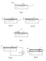
- Figure 6 is a schematic illustration of a sensor and insertion assembly 2 for intravascular measurement of pressure in a living body according to the present invention, comprising a insertion means 4 and a sensor chip 6.
- the invention generally relates to a pressure sensor for in-vivo measurements of pressure, e.g. to perform intravascular measurements, but also other in-vivo measurements such as measuring intracranial pressure.
- the sensor and insertion assembly comprises a guide wire assembly including a core wire of the kind, e.g. disclosed in the above-mentioned US patent Re. 35,648 , which is incorporated herein in its entirety.
- FIG 1 is a schematic illustration showing a cross sectional view of a sensor chip 6 according to a first embodiment of the present invention.
- the sensor chip 6 includes a substrate body 8 that comprises a recess covered by a pressure sensitive film 10 thereby forming a cavity 12.
- a piezoelectric element 14 is arranged in connection with the pressure sensitive film, and an energy feeding means 16 (see figure 7) is adapted to apply energy to the piezoelectric element such that acoustic waves are generated in the element.
- the piezoelectric element then generates an output signal, representing the pressure at the film, in dependence of measured properties of the acoustic waves related to the deflection of the pressure sensitive film.
- the piezoelectric element is in the form of an elastic piezoelectric film being the pressure sensitive film.
- Figure 2a is a schematic illustration showing a cross sectional view of a sensor chip according to a second embodiment of the present invention where the pressure sensitive film is attached to the substrate body and the piezoelectric film is attached on said pressure sensitive film.
- Figure 2b is a schematic illustration showing a cross sectional view of a sensor chip according to a third embodiment of the present invention where the piezoelectric film is attached to the substrate body and the pressure sensitive film is attached on said piezoelectric film.
- the energy is preferably applied to, and obtained from, the piezoelectric film via a pair of interdigital transducers (IDT) 20 and 22 (see figure 5), respectively.
- IDT interdigital transducers
- FIG 5 is a schematic illustration of a top view of a sensor chip according to the present invention.
- the IDTs are either arranged on the side of the piezoelectric film facing the substrate body, or on the opposite side of the film. The inventor has found that by arranging the IDTs on the side of the piezoelectric film facing the substrate body advantageous impedance performance may be obtained.
- one of said IDTs is arranged on one side of the piezoelectric film and the other is arranged on the opposite side.
- the piezoelectric film preferably covers the entire recess, however, as an alternative, the film may cover only a part of the recess.
- the piezoelectric element is a piezoelectric beam 14' arranged on said pressure sensitive film.
- This embodiment is illustrated in figure 3 schematically showing a cross sectional view of a sensor chip.
- the piezoelectric beam is encapsulated and arranged where the highest signal amplitude is expected dependent of the deflection of the film, as an example this may be close to the border of the recess.
- One further piezoelectric beam may also be arranged to be used for obtaining a reference pressure and in that case the beam is arranged where no, or very low, signal is expected.
- the piezoelectric beam 14' may be arranged in the recess, i.e. under the pressure sensitive film.
- the pressure sensitive film that covers the recess is electrically insulated from the substrate body by an insulating film 15.
- the piezoelectric element preferably in the form of a piezoelectric crystal, is connected to the pressure sensitive film and the substrate body such that a capacitive pressure sensor is created being a resonance circuit having a resonance frequency dependent upon the pressure on the film.
- the created capacitance is illustrated in the figure by a capacitor (dotted) between the film and the substrate body.
- a piezoelectric element in the form of a piezoelectric film 14"', is arranged within the cavity 12 and separated from the pressure sensitive film 10 by an insulating film 15.
- the energy is preferably applied to, and obtained from, the piezoelectric film via a pair of interdigital transducers (IDT), not shown in the figure.
- IDT interdigital transducers
- this variant covers the general concept of arranging the piezoelectric element within the cavity, or physically connected to the reference cavity of a capacitive pressure sensor.
- One of the electrodes used to apply energy to the piezoelectric film may in addition be used for connection with the pressure sensitive film.
- the electrodes used for connection with the piezoelectric film and pressure sensitive film, respectively may be connected together outside the cavity.
- the energy supplied to the piezoelectric element is supplied by the energy feeding means that is connected to an electrical cable connected to an external energy generator (not shown).
- the energy feeding means is connected to an antenna for wireless connection to the external energy generator.
- the energy feeding means may be connected to a miniature battery means (not shown) arranged in connection with the sensor chip.
- the generated output signal may be wirelessly transmitted to a processing unit 18 (see figure 6) or transmitted to the processing unit via electrical cables.
- the processing unit is preferably arranged at the same substrate body as the pressure sensor. This is particularly advantageous from a manufacturing point of view, but also in order to achieve a high signal to noise ratio.
- Another alternative is to arrange the processing unit as a separate part arranged at the distal end of the core wire close to the sensor chip.
- a still further alternative is to arrange the processing unit at an external unit 24 (figure 7).
- the processing unit determines the pressure based upon properties of the output signal which may be derived by measuring of bulk acoustic waves (BAW) through said piezoelectric element, or by measuring of surface acoustic waves (SAW) on said piezoelectric element, or by measuring of lamb waves of said piezoelectric element.
- BAW bulk acoustic waves
- SAW surface acoustic waves
- the cavity preferably is evacuated and that the generated pressure signal then represents the absolute pressure. If the cavity not is evacuated, a reference pressure has to be used as a reference value for the pressure determined by the pressure sensor.
- the pressure sensitive film is preferably made from silicon (Si) and the piezoelectric film is made from any of PZT, ZnO, BaTiO 3 or ANI.
- the piezoelectric film has a thickness of less than 100 ⁇ m, preferably in the range of 0,1 - 20 ⁇ m
- the sensor chip has a thickness preferably in the interval 0,05 - 2 mm, a length of less than 10 mm and a width of less than 2 mm.
- the pressure sensor according to the invention may also be a separate self-contained device, i.e. not arranged at any insertion means, and may then be used both in medical, e.g. to perform intra-cranial measurements, and non-medical applications, e.g. to perform pressure measurements in tyres and in dangerous environments.
- the pressure sensor In both the medical and non-medical application the pressure sensor must be provided with an energy means, e.g. a miniature battery or a rechargeable capacitor, and a communication means, e.g. a telemetry coil.
- the assembly includes temperature compensating means to compensate for temperature variations that influence the measurement.
- the assembly further includes a temperature measurement means adapted to measure the temperature in the living body.
- a temperature measurement means adapted to measure the temperature in the living body.
- FIG 8 showing a top view of a sensor chip according to an alternative embodiment of the present invention.
- the sensor chip 6 comprises a recess 12, preferably covered by a flexible film (not shown) and a piezoelectric element 14, here in the form of a strip above a part of the recess.
- the sensor chip 6 is further provided with an additional piezoelectric element 14"" in the form of a strip. Energy is applied to the additional piezoelectric element 14"" via the IDT 20 and an output signal that vary in dependence of the ambient temperature is available at IDT 22.
- the energy applied to the pressure sensor via IDT 20 may have a first resonant frequency, f1, and the energy applied to the temperature sensor via IDT 22 may have a second resonant frequency, f2, and the frequencies of the respective output signals will then vary in accordance with the measured pressure and temperature, respectively.
Landscapes
- Health & Medical Sciences (AREA)
- Physics & Mathematics (AREA)
- Life Sciences & Earth Sciences (AREA)
- General Physics & Mathematics (AREA)
- Cardiology (AREA)
- Engineering & Computer Science (AREA)
- Molecular Biology (AREA)
- Vascular Medicine (AREA)
- Biophysics (AREA)
- Pathology (AREA)
- Acoustics & Sound (AREA)
- Biomedical Technology (AREA)
- Heart & Thoracic Surgery (AREA)
- Medical Informatics (AREA)
- Physiology (AREA)
- Surgery (AREA)
- Animal Behavior & Ethology (AREA)
- General Health & Medical Sciences (AREA)
- Public Health (AREA)
- Veterinary Medicine (AREA)
- Measuring Pulse, Heart Rate, Blood Pressure Or Blood Flow (AREA)
- Measuring Fluid Pressure (AREA)
Priority Applications (3)
| Application Number | Priority Date | Filing Date | Title |
|---|---|---|---|
| EP06111452A EP1837638B1 (de) | 2006-03-21 | 2006-03-21 | Drucksensor |
| AT06111452T ATE539336T1 (de) | 2006-03-21 | 2006-03-21 | Drucksensor |
| JP2007075131A JP5138246B2 (ja) | 2006-03-21 | 2007-03-22 | 圧力センサ |
Applications Claiming Priority (1)
| Application Number | Priority Date | Filing Date | Title |
|---|---|---|---|
| EP06111452A EP1837638B1 (de) | 2006-03-21 | 2006-03-21 | Drucksensor |
Publications (2)
| Publication Number | Publication Date |
|---|---|
| EP1837638A1 true EP1837638A1 (de) | 2007-09-26 |
| EP1837638B1 EP1837638B1 (de) | 2011-12-28 |
Family
ID=36691626
Family Applications (1)
| Application Number | Title | Priority Date | Filing Date |
|---|---|---|---|
| EP06111452A Expired - Lifetime EP1837638B1 (de) | 2006-03-21 | 2006-03-21 | Drucksensor |
Country Status (2)
| Country | Link |
|---|---|
| EP (1) | EP1837638B1 (de) |
| AT (1) | ATE539336T1 (de) |
Cited By (14)
| Publication number | Priority date | Publication date | Assignee | Title |
|---|---|---|---|---|
| WO2012058973A1 (zh) * | 2010-11-01 | 2012-05-10 | 香港纺织及成衣研发中心 | 薄膜型风压传感器及相应的无线传感网络 |
| WO2015051770A1 (en) * | 2013-10-08 | 2015-04-16 | Linet Spol. S R.O. | Device for contactless monitoring of patient's vital signs |
| CN106618547A (zh) * | 2017-01-18 | 2017-05-10 | 哈尔滨工业大学深圳研究生院 | 一种测量脑颅压的系统、方法和装置 |
| EP3254610A1 (de) * | 2016-06-09 | 2017-12-13 | Heraeus Deutschland GmbH & Co. KG | Führungsdrahtsystem |
| WO2018055367A3 (en) * | 2016-09-21 | 2018-05-03 | Imperial Innovations Limited | Implantable intravascular pressure sensing apparatus and method of operating it |
| CN109222917A (zh) * | 2017-07-10 | 2019-01-18 | 中国科学院微电子研究所 | 脉搏波传感器、传感器阵列及脉搏波测量方法 |
| WO2019162672A1 (en) * | 2018-02-20 | 2019-08-29 | Imperial Innovations Limited | An apparatus and method |
| US10702170B2 (en) | 2013-07-01 | 2020-07-07 | Zurich Medical Corporation | Apparatus and method for intravascular measurements |
| US10835183B2 (en) | 2013-07-01 | 2020-11-17 | Zurich Medical Corporation | Apparatus and method for intravascular measurements |
| WO2021181083A1 (en) * | 2020-03-09 | 2021-09-16 | Imperial College Innovations Limited | Pressure sensor |
| US11284808B2 (en) | 2014-10-11 | 2022-03-29 | Linet Spol. S.R.O. | Device and method for measurement of vital functions, including intracranial pressure, and system and method for collecting data |
| CN117330234A (zh) * | 2023-11-28 | 2024-01-02 | 微智医疗器械有限公司 | 一种压力传感器组件制作方法及压力传感器组件 |
| US12150787B2 (en) | 2018-03-29 | 2024-11-26 | Ip2Ipo Innovations Limited | Cardiac mesh with pressure sensor |
| US12415048B2 (en) | 2019-12-10 | 2025-09-16 | Trudell Medical International Inc. | Integrated dose counter |
Families Citing this family (2)
| Publication number | Priority date | Publication date | Assignee | Title |
|---|---|---|---|---|
| CN103462595B (zh) * | 2013-09-22 | 2015-10-21 | 天津普仁万合信息技术有限公司 | 一种便携式传感器组件 |
| CN105060238B (zh) * | 2015-07-09 | 2018-05-29 | 武汉大学 | 基于超薄膜的电容式压力传感器的制作方法 |
Citations (6)
| Publication number | Priority date | Publication date | Assignee | Title |
|---|---|---|---|---|
| GB2235533A (en) | 1989-08-11 | 1991-03-06 | Stc Plc | Piezoelectric sensor device |
| US5189914A (en) * | 1988-02-29 | 1993-03-02 | The Regents Of The University Of California | Plate-mode ultrasonic sensor |
| US20010037066A1 (en) * | 2000-03-21 | 2001-11-01 | Leif Smith | Resonance based pressure transducer system |
| US20030094431A1 (en) * | 2001-11-20 | 2003-05-22 | Tai-Kang Shing | Method for making a thin film bulk acoustic-wave resonator |
| US20050067920A1 (en) | 2003-09-30 | 2005-03-31 | Weinberg Marc S. | Flexural plate wave sensor |
| WO2005058166A1 (en) | 2003-12-15 | 2005-06-30 | Imperial College Innovations Ltd. | Acoustic wave devices |
Family Cites Families (1)
| Publication number | Priority date | Publication date | Assignee | Title |
|---|---|---|---|---|
| EP1764597B1 (de) * | 2005-09-16 | 2011-03-23 | STMicroelectronics Srl | Druckwandler mit akoustischen Oberflächenwellen |
-
2006
- 2006-03-21 AT AT06111452T patent/ATE539336T1/de active
- 2006-03-21 EP EP06111452A patent/EP1837638B1/de not_active Expired - Lifetime
Patent Citations (6)
| Publication number | Priority date | Publication date | Assignee | Title |
|---|---|---|---|---|
| US5189914A (en) * | 1988-02-29 | 1993-03-02 | The Regents Of The University Of California | Plate-mode ultrasonic sensor |
| GB2235533A (en) | 1989-08-11 | 1991-03-06 | Stc Plc | Piezoelectric sensor device |
| US20010037066A1 (en) * | 2000-03-21 | 2001-11-01 | Leif Smith | Resonance based pressure transducer system |
| US20030094431A1 (en) * | 2001-11-20 | 2003-05-22 | Tai-Kang Shing | Method for making a thin film bulk acoustic-wave resonator |
| US20050067920A1 (en) | 2003-09-30 | 2005-03-31 | Weinberg Marc S. | Flexural plate wave sensor |
| WO2005058166A1 (en) | 2003-12-15 | 2005-06-30 | Imperial College Innovations Ltd. | Acoustic wave devices |
Cited By (24)
| Publication number | Priority date | Publication date | Assignee | Title |
|---|---|---|---|---|
| WO2012058973A1 (zh) * | 2010-11-01 | 2012-05-10 | 香港纺织及成衣研发中心 | 薄膜型风压传感器及相应的无线传感网络 |
| US10835183B2 (en) | 2013-07-01 | 2020-11-17 | Zurich Medical Corporation | Apparatus and method for intravascular measurements |
| US11471061B2 (en) | 2013-07-01 | 2022-10-18 | Zurich Medical Corporation | Apparatus and method for intravascular measurements |
| US10702170B2 (en) | 2013-07-01 | 2020-07-07 | Zurich Medical Corporation | Apparatus and method for intravascular measurements |
| WO2015051770A1 (en) * | 2013-10-08 | 2015-04-16 | Linet Spol. S R.O. | Device for contactless monitoring of patient's vital signs |
| CN105813551A (zh) * | 2013-10-08 | 2016-07-27 | 林内特斯波尔有限公司 | 用于非接触地监测患者生命体征的设备 |
| CN105813551B (zh) * | 2013-10-08 | 2019-07-26 | 林内特斯波尔有限公司 | 用于非接触地监测患者生命体征的设备 |
| US10376216B2 (en) | 2013-10-08 | 2019-08-13 | Linet Spol. S R.O. | Device for contactless monitoring of patient's vital signs |
| US11284808B2 (en) | 2014-10-11 | 2022-03-29 | Linet Spol. S.R.O. | Device and method for measurement of vital functions, including intracranial pressure, and system and method for collecting data |
| EP3254610A1 (de) * | 2016-06-09 | 2017-12-13 | Heraeus Deutschland GmbH & Co. KG | Führungsdrahtsystem |
| US10881837B2 (en) | 2016-06-09 | 2021-01-05 | Heraeus Deutschland GmbH & Co. KG | Guidewire system |
| US11813045B2 (en) | 2016-09-21 | 2023-11-14 | Ip2Ipo Innovations Limited | Implantable intravascular pressure sensing apparatus and method of operating it |
| WO2018055367A3 (en) * | 2016-09-21 | 2018-05-03 | Imperial Innovations Limited | Implantable intravascular pressure sensing apparatus and method of operating it |
| CN106618547A (zh) * | 2017-01-18 | 2017-05-10 | 哈尔滨工业大学深圳研究生院 | 一种测量脑颅压的系统、方法和装置 |
| CN109222917A (zh) * | 2017-07-10 | 2019-01-18 | 中国科学院微电子研究所 | 脉搏波传感器、传感器阵列及脉搏波测量方法 |
| CN109222917B (zh) * | 2017-07-10 | 2022-04-26 | 中国科学院微电子研究所 | 脉搏波传感器、传感器阵列及脉搏波测量方法 |
| WO2019162672A1 (en) * | 2018-02-20 | 2019-08-29 | Imperial Innovations Limited | An apparatus and method |
| US12502137B2 (en) | 2018-02-20 | 2025-12-23 | Ip2Ipo Innovations Limited | Implantable cardiovascular sensor |
| US12150787B2 (en) | 2018-03-29 | 2024-11-26 | Ip2Ipo Innovations Limited | Cardiac mesh with pressure sensor |
| US12415048B2 (en) | 2019-12-10 | 2025-09-16 | Trudell Medical International Inc. | Integrated dose counter |
| WO2021181083A1 (en) * | 2020-03-09 | 2021-09-16 | Imperial College Innovations Limited | Pressure sensor |
| US12622593B2 (en) | 2020-03-09 | 2026-05-12 | Imperial College Innovations Limited | Pressure sensor |
| CN117330234A (zh) * | 2023-11-28 | 2024-01-02 | 微智医疗器械有限公司 | 一种压力传感器组件制作方法及压力传感器组件 |
| CN117330234B (zh) * | 2023-11-28 | 2024-03-15 | 微智医疗器械有限公司 | 一种压力传感器组件制作方法及压力传感器组件 |
Also Published As
| Publication number | Publication date |
|---|---|
| EP1837638B1 (de) | 2011-12-28 |
| ATE539336T1 (de) | 2012-01-15 |
Similar Documents
| Publication | Publication Date | Title |
|---|---|---|
| US7331236B2 (en) | Pressure sensor | |
| JP5138246B2 (ja) | 圧力センサ | |
| EP1837638B1 (de) | Drucksensor | |
| US12502137B2 (en) | Implantable cardiovascular sensor | |
| US7243547B2 (en) | MEMS SAW sensor | |
| US7205701B2 (en) | Passive wireless acoustic wave chemical sensor | |
| EP3515291B1 (de) | Interdigitaler wandler für einen implantierbaren intravaskulären drucksensor | |
| US8258674B2 (en) | Surface acoustic wave sensor and system | |
| EP3534784B1 (de) | Implantierbare vorrichtung zum messen des intravaskulären drucks | |
| US7825568B2 (en) | Electro acoustic sensor for high pressure environments | |
| WO2007073473A1 (en) | Acoustic wave device used as rfid and as sensor | |
| US7100451B2 (en) | Surface acoustic wave sensing system and method for measuring pressure and temperature | |
| JP4811972B2 (ja) | 超音波診断装置 | |
| JPH07270261A (ja) | 3端子構造を有する圧電振動子を用いた圧覚及び触覚センサ | |
| US20260083435A1 (en) | Improved saw-sensor with thin piezoelectric layer and osmotic sensor device including the same | |
| US20080167563A1 (en) | Non-invasive blood flow monitor | |
| Moradian | Development of RF-MEMS based passive wireless respiratory monitoring systems | |
| FR3100330A1 (fr) | Capteurs de pression à ondes acoustiques différentiels | |
| GB2571142A (en) | Apparatus and method | |
| JP5780347B2 (ja) | 生体検査装置 | |
| JP7351508B2 (ja) | 認識信号生成素子及び素子認識システム | |
| RU2632575C1 (ru) | Чувствительный элемент для акустического жидкостного сенсора | |
| CN106618547A (zh) | 一种测量脑颅压的系统、方法和装置 |
Legal Events
| Date | Code | Title | Description |
|---|---|---|---|
| PUAI | Public reference made under article 153(3) epc to a published international application that has entered the european phase |
Free format text: ORIGINAL CODE: 0009012 |
|
| AK | Designated contracting states |
Kind code of ref document: A1 Designated state(s): AT BE BG CH CY CZ DE DK EE ES FI FR GB GR HU IE IS IT LI LT LU LV MC NL PL PT RO SE SI SK TR |
|
| AX | Request for extension of the european patent |
Extension state: AL BA HR MK YU |
|
| 17P | Request for examination filed |
Effective date: 20071017 |
|
| RIN1 | Information on inventor provided before grant (corrected) |
Inventor name: TULKKI, SAULIRADI MEDICAL SYSTEMS CO., LTD. Inventor name: SMITH, LEIF |
|
| 17Q | First examination report despatched |
Effective date: 20071108 |
|
| AKX | Designation fees paid |
Designated state(s): AT BE BG CH CY CZ DE DK EE ES FI FR GB GR HU IE IS IT LI LT LU LV MC NL PL PT RO SE SI SK TR |
|
| GRAP | Despatch of communication of intention to grant a patent |
Free format text: ORIGINAL CODE: EPIDOSNIGR1 |
|
| RIN1 | Information on inventor provided before grant (corrected) |
Inventor name: TULKKI, SAULI Inventor name: SMITH, LEIF |
|
| GRAS | Grant fee paid |
Free format text: ORIGINAL CODE: EPIDOSNIGR3 |
|
| GRAA | (expected) grant |
Free format text: ORIGINAL CODE: 0009210 |
|
| AK | Designated contracting states |
Kind code of ref document: B1 Designated state(s): AT BE BG CH CY CZ DE DK EE ES FI FR GB GR HU IE IS IT LI LT LU LV MC NL PL PT RO SE SI SK TR |
|
| REG | Reference to a national code |
Ref country code: GB Ref legal event code: FG4D |
|
| REG | Reference to a national code |
Ref country code: CH Ref legal event code: EP |
|
| REG | Reference to a national code |
Ref country code: DE Ref legal event code: R081 Ref document number: 602006026647 Country of ref document: DE Owner name: ST. JUDE MEDICAL COORDINATION CENTER BVBA, BE Free format text: FORMER OWNER: RADI MEDICAL SYSTEMS AB, UPPSALA, SE |
|
| REG | Reference to a national code |
Ref country code: AT Ref legal event code: REF Ref document number: 539336 Country of ref document: AT Kind code of ref document: T Effective date: 20120115 |
|
| REG | Reference to a national code |
Ref country code: IE Ref legal event code: FG4D |
|
| REG | Reference to a national code |
Ref country code: DE Ref legal event code: R096 Ref document number: 602006026647 Country of ref document: DE Effective date: 20120308 |
|
| REG | Reference to a national code |
Ref country code: NL Ref legal event code: VDEP Effective date: 20111228 |
|
| REG | Reference to a national code |
Ref country code: SE Ref legal event code: TRGR |
|
| PG25 | Lapsed in a contracting state [announced via postgrant information from national office to epo] |
Ref country code: LT Free format text: LAPSE BECAUSE OF FAILURE TO SUBMIT A TRANSLATION OF THE DESCRIPTION OR TO PAY THE FEE WITHIN THE PRESCRIBED TIME-LIMIT Effective date: 20111228 |
|
| LTIE | Lt: invalidation of european patent or patent extension |
Effective date: 20111228 |
|
| PG25 | Lapsed in a contracting state [announced via postgrant information from national office to epo] |
Ref country code: GR Free format text: LAPSE BECAUSE OF FAILURE TO SUBMIT A TRANSLATION OF THE DESCRIPTION OR TO PAY THE FEE WITHIN THE PRESCRIBED TIME-LIMIT Effective date: 20120329 Ref country code: LV Free format text: LAPSE BECAUSE OF FAILURE TO SUBMIT A TRANSLATION OF THE DESCRIPTION OR TO PAY THE FEE WITHIN THE PRESCRIBED TIME-LIMIT Effective date: 20111228 Ref country code: SI Free format text: LAPSE BECAUSE OF FAILURE TO SUBMIT A TRANSLATION OF THE DESCRIPTION OR TO PAY THE FEE WITHIN THE PRESCRIBED TIME-LIMIT Effective date: 20111228 |
|
| PG25 | Lapsed in a contracting state [announced via postgrant information from national office to epo] |
Ref country code: BE Free format text: LAPSE BECAUSE OF FAILURE TO SUBMIT A TRANSLATION OF THE DESCRIPTION OR TO PAY THE FEE WITHIN THE PRESCRIBED TIME-LIMIT Effective date: 20111228 Ref country code: CY Free format text: LAPSE BECAUSE OF FAILURE TO SUBMIT A TRANSLATION OF THE DESCRIPTION OR TO PAY THE FEE WITHIN THE PRESCRIBED TIME-LIMIT Effective date: 20111228 |
|
| PG25 | Lapsed in a contracting state [announced via postgrant information from national office to epo] |
Ref country code: CZ Free format text: LAPSE BECAUSE OF FAILURE TO SUBMIT A TRANSLATION OF THE DESCRIPTION OR TO PAY THE FEE WITHIN THE PRESCRIBED TIME-LIMIT Effective date: 20111228 Ref country code: SK Free format text: LAPSE BECAUSE OF FAILURE TO SUBMIT A TRANSLATION OF THE DESCRIPTION OR TO PAY THE FEE WITHIN THE PRESCRIBED TIME-LIMIT Effective date: 20111228 Ref country code: NL Free format text: LAPSE BECAUSE OF FAILURE TO SUBMIT A TRANSLATION OF THE DESCRIPTION OR TO PAY THE FEE WITHIN THE PRESCRIBED TIME-LIMIT Effective date: 20111228 Ref country code: IS Free format text: LAPSE BECAUSE OF FAILURE TO SUBMIT A TRANSLATION OF THE DESCRIPTION OR TO PAY THE FEE WITHIN THE PRESCRIBED TIME-LIMIT Effective date: 20120428 Ref country code: BG Free format text: LAPSE BECAUSE OF FAILURE TO SUBMIT A TRANSLATION OF THE DESCRIPTION OR TO PAY THE FEE WITHIN THE PRESCRIBED TIME-LIMIT Effective date: 20120328 Ref country code: EE Free format text: LAPSE BECAUSE OF FAILURE TO SUBMIT A TRANSLATION OF THE DESCRIPTION OR TO PAY THE FEE WITHIN THE PRESCRIBED TIME-LIMIT Effective date: 20111228 |
|
| PG25 | Lapsed in a contracting state [announced via postgrant information from national office to epo] |
Ref country code: PT Free format text: LAPSE BECAUSE OF FAILURE TO SUBMIT A TRANSLATION OF THE DESCRIPTION OR TO PAY THE FEE WITHIN THE PRESCRIBED TIME-LIMIT Effective date: 20120430 Ref country code: RO Free format text: LAPSE BECAUSE OF FAILURE TO SUBMIT A TRANSLATION OF THE DESCRIPTION OR TO PAY THE FEE WITHIN THE PRESCRIBED TIME-LIMIT Effective date: 20111228 Ref country code: PL Free format text: LAPSE BECAUSE OF FAILURE TO SUBMIT A TRANSLATION OF THE DESCRIPTION OR TO PAY THE FEE WITHIN THE PRESCRIBED TIME-LIMIT Effective date: 20111228 |
|
| REG | Reference to a national code |
Ref country code: AT Ref legal event code: MK05 Ref document number: 539336 Country of ref document: AT Kind code of ref document: T Effective date: 20111228 |
|
| PG25 | Lapsed in a contracting state [announced via postgrant information from national office to epo] |
Ref country code: DK Free format text: LAPSE BECAUSE OF FAILURE TO SUBMIT A TRANSLATION OF THE DESCRIPTION OR TO PAY THE FEE WITHIN THE PRESCRIBED TIME-LIMIT Effective date: 20111228 Ref country code: MC Free format text: LAPSE BECAUSE OF NON-PAYMENT OF DUE FEES Effective date: 20120331 |
|
| REG | Reference to a national code |
Ref country code: CH Ref legal event code: PL |
|
| PLBE | No opposition filed within time limit |
Free format text: ORIGINAL CODE: 0009261 |
|
| STAA | Information on the status of an ep patent application or granted ep patent |
Free format text: STATUS: NO OPPOSITION FILED WITHIN TIME LIMIT |
|
| PG25 | Lapsed in a contracting state [announced via postgrant information from national office to epo] |
Ref country code: IT Free format text: LAPSE BECAUSE OF FAILURE TO SUBMIT A TRANSLATION OF THE DESCRIPTION OR TO PAY THE FEE WITHIN THE PRESCRIBED TIME-LIMIT Effective date: 20111228 |
|
| 26N | No opposition filed |
Effective date: 20121001 |
|
| REG | Reference to a national code |
Ref country code: IE Ref legal event code: MM4A |
|
| REG | Reference to a national code |
Ref country code: DE Ref legal event code: R097 Ref document number: 602006026647 Country of ref document: DE Effective date: 20121001 |
|
| PG25 | Lapsed in a contracting state [announced via postgrant information from national office to epo] |
Ref country code: LI Free format text: LAPSE BECAUSE OF NON-PAYMENT OF DUE FEES Effective date: 20120331 Ref country code: IE Free format text: LAPSE BECAUSE OF NON-PAYMENT OF DUE FEES Effective date: 20120321 Ref country code: AT Free format text: LAPSE BECAUSE OF FAILURE TO SUBMIT A TRANSLATION OF THE DESCRIPTION OR TO PAY THE FEE WITHIN THE PRESCRIBED TIME-LIMIT Effective date: 20111228 Ref country code: CH Free format text: LAPSE BECAUSE OF NON-PAYMENT OF DUE FEES Effective date: 20120331 |
|
| PG25 | Lapsed in a contracting state [announced via postgrant information from national office to epo] |
Ref country code: ES Free format text: LAPSE BECAUSE OF FAILURE TO SUBMIT A TRANSLATION OF THE DESCRIPTION OR TO PAY THE FEE WITHIN THE PRESCRIBED TIME-LIMIT Effective date: 20120408 |
|
| PG25 | Lapsed in a contracting state [announced via postgrant information from national office to epo] |
Ref country code: FI Free format text: LAPSE BECAUSE OF FAILURE TO SUBMIT A TRANSLATION OF THE DESCRIPTION OR TO PAY THE FEE WITHIN THE PRESCRIBED TIME-LIMIT Effective date: 20111228 |
|
| PG25 | Lapsed in a contracting state [announced via postgrant information from national office to epo] |
Ref country code: TR Free format text: LAPSE BECAUSE OF FAILURE TO SUBMIT A TRANSLATION OF THE DESCRIPTION OR TO PAY THE FEE WITHIN THE PRESCRIBED TIME-LIMIT Effective date: 20111228 |
|
| PG25 | Lapsed in a contracting state [announced via postgrant information from national office to epo] |
Ref country code: LU Free format text: LAPSE BECAUSE OF NON-PAYMENT OF DUE FEES Effective date: 20120321 |
|
| PG25 | Lapsed in a contracting state [announced via postgrant information from national office to epo] |
Ref country code: HU Free format text: LAPSE BECAUSE OF FAILURE TO SUBMIT A TRANSLATION OF THE DESCRIPTION OR TO PAY THE FEE WITHIN THE PRESCRIBED TIME-LIMIT Effective date: 20060321 |
|
| REG | Reference to a national code |
Ref country code: FR Ref legal event code: PLFP Year of fee payment: 10 |
|
| REG | Reference to a national code |
Ref country code: DE Ref legal event code: R082 Ref document number: 602006026647 Country of ref document: DE Representative=s name: BRANN AB, SE Ref country code: DE Ref legal event code: R081 Ref document number: 602006026647 Country of ref document: DE Owner name: ST. JUDE MEDICAL COORDINATION CENTER BVBA, BE Free format text: FORMER OWNER: RADI MEDICAL SYSTEMS AB, UPPSALA, SE |
|
| REG | Reference to a national code |
Ref country code: GB Ref legal event code: 732E Free format text: REGISTERED BETWEEN 20150827 AND 20150902 |
|
| REG | Reference to a national code |
Ref country code: FR Ref legal event code: TP Owner name: ST. JUDE MEDICAL COORDINATION CENTER BVBA, BE Effective date: 20160113 |
|
| REG | Reference to a national code |
Ref country code: FR Ref legal event code: PLFP Year of fee payment: 11 |
|
| REG | Reference to a national code |
Ref country code: DE Ref legal event code: R082 Ref document number: 602006026647 Country of ref document: DE |
|
| REG | Reference to a national code |
Ref country code: FR Ref legal event code: PLFP Year of fee payment: 12 |
|
| REG | Reference to a national code |
Ref country code: FR Ref legal event code: PLFP Year of fee payment: 13 |
|
| PGFP | Annual fee paid to national office [announced via postgrant information from national office to epo] |
Ref country code: GB Payment date: 20180327 Year of fee payment: 13 |
|
| PGFP | Annual fee paid to national office [announced via postgrant information from national office to epo] |
Ref country code: SE Payment date: 20180328 Year of fee payment: 13 Ref country code: FR Payment date: 20180326 Year of fee payment: 13 |
|
| PGFP | Annual fee paid to national office [announced via postgrant information from national office to epo] |
Ref country code: DE Payment date: 20180328 Year of fee payment: 13 |
|
| REG | Reference to a national code |
Ref country code: DE Ref legal event code: R119 Ref document number: 602006026647 Country of ref document: DE |
|
| REG | Reference to a national code |
Ref country code: SE Ref legal event code: EUG |
|
| PG25 | Lapsed in a contracting state [announced via postgrant information from national office to epo] |
Ref country code: SE Free format text: LAPSE BECAUSE OF NON-PAYMENT OF DUE FEES Effective date: 20190322 |
|
| GBPC | Gb: european patent ceased through non-payment of renewal fee |
Effective date: 20190321 |
|
| PG25 | Lapsed in a contracting state [announced via postgrant information from national office to epo] |
Ref country code: DE Free format text: LAPSE BECAUSE OF NON-PAYMENT OF DUE FEES Effective date: 20191001 Ref country code: GB Free format text: LAPSE BECAUSE OF NON-PAYMENT OF DUE FEES Effective date: 20190321 |
|
| PG25 | Lapsed in a contracting state [announced via postgrant information from national office to epo] |
Ref country code: FR Free format text: LAPSE BECAUSE OF NON-PAYMENT OF DUE FEES Effective date: 20190331 |