EP1837687A1 - Commutateur optique doté d'éléments de réglage d'angle et de collimateurs à fibres multiples - Google Patents
Commutateur optique doté d'éléments de réglage d'angle et de collimateurs à fibres multiples Download PDFInfo
- Publication number
- EP1837687A1 EP1837687A1 EP07103812A EP07103812A EP1837687A1 EP 1837687 A1 EP1837687 A1 EP 1837687A1 EP 07103812 A EP07103812 A EP 07103812A EP 07103812 A EP07103812 A EP 07103812A EP 1837687 A1 EP1837687 A1 EP 1837687A1
- Authority
- EP
- European Patent Office
- Prior art keywords
- optical
- optical switch
- optical beam
- prism
- path
- Prior art date
- Legal status (The legal status is an assumption and is not a legal conclusion. Google has not performed a legal analysis and makes no representation as to the accuracy of the status listed.)
- Granted
Links
- 230000003287 optical effect Effects 0.000 title claims abstract description 169
- 239000000835 fiber Substances 0.000 title claims abstract description 62
- 238000004519 manufacturing process Methods 0.000 description 3
- 239000013307 optical fiber Substances 0.000 description 3
- 239000013078 crystal Substances 0.000 description 2
- 238000012544 monitoring process Methods 0.000 description 2
- 241000282337 Nasua nasua Species 0.000 description 1
- 239000006117 anti-reflective coating Substances 0.000 description 1
- 230000008878 coupling Effects 0.000 description 1
- 238000010168 coupling process Methods 0.000 description 1
- 238000005859 coupling reaction Methods 0.000 description 1
- 230000037361 pathway Effects 0.000 description 1
- 239000000758 substrate Substances 0.000 description 1
Images


Classifications
-
- G—PHYSICS
- G02—OPTICS
- G02B—OPTICAL ELEMENTS, SYSTEMS OR APPARATUS
- G02B6/00—Light guides; Structural details of arrangements comprising light guides and other optical elements, e.g. couplings
- G02B6/24—Coupling light guides
- G02B6/26—Optical coupling means
- G02B6/35—Optical coupling means having switching means
- G02B6/351—Optical coupling means having switching means involving stationary waveguides with moving interposed optical elements
- G02B6/3524—Optical coupling means having switching means involving stationary waveguides with moving interposed optical elements the optical element being refractive
- G02B6/3528—Optical coupling means having switching means involving stationary waveguides with moving interposed optical elements the optical element being refractive the optical element being a prism
-
- G—PHYSICS
- G02—OPTICS
- G02B—OPTICAL ELEMENTS, SYSTEMS OR APPARATUS
- G02B6/00—Light guides; Structural details of arrangements comprising light guides and other optical elements, e.g. couplings
- G02B6/24—Coupling light guides
- G02B6/26—Optical coupling means
- G02B6/35—Optical coupling means having switching means
- G02B6/351—Optical coupling means having switching means involving stationary waveguides with moving interposed optical elements
- G02B6/3512—Optical coupling means having switching means involving stationary waveguides with moving interposed optical elements the optical element being reflective, e.g. mirror
-
- G—PHYSICS
- G02—OPTICS
- G02B—OPTICAL ELEMENTS, SYSTEMS OR APPARATUS
- G02B6/00—Light guides; Structural details of arrangements comprising light guides and other optical elements, e.g. couplings
- G02B6/24—Coupling light guides
- G02B6/26—Optical coupling means
- G02B6/35—Optical coupling means having switching means
- G02B6/354—Switching arrangements, i.e. number of input/output ports and interconnection types
- G02B6/3554—3D constellations, i.e. with switching elements and switched beams located in a volume
- G02B6/3556—NxM switch, i.e. regular arrays of switches elements of matrix type constellation
Definitions
- the present invention relates generally to an optical switch, and more specifically to an optical switch with angle tuning elements and multiple-fiber collimators that perform optical signal switching between input and output optical pathways.
- Optical switches are widely deployed in optical networks to provide functions such as light path routing, protection switching, and system performance monitoring.
- the switching function is generally achieved by mechanically moving fiber or other bulk optic elements using stepper motors, controlled actuators or electrical relays.
- Various examples of optical switches are disclosed in U.S. Patent Application Serial No. 11/070,450 , entitled “Optical Switch,” filed March 1, 2005, the entire contents of which are incorporated herein by reference.
- the form factor of an optical switch is an important design consideration. Compact form factors are often desirable and are required in increasing number of applications, but invariably there exist practical limits on how much a design can be miniaturized.
- the present invention provides various configurations for an optical switch that allow the optical switch to be designed with smaller form factors.
- the present invention incorporates multiple-fiber collimators with angle tuning elements into an optical switch in innovative ways to reduce the form factor and also to reduce costs and improve the stability and performance reliability of the optical switch design.
- the optical switch includes a pair of collimators that are aligned with an optical axis of the optical switch, and an angle tuning element between the two collimators for deflecting an optical beam output from one collimator into the other collimator.
- One or both of the collimators may have multiple fibers.
- the optical switch is capable of 1xN switching, where N is an integer equal to 2 or more.
- the optical switch is capable of MxN switching, where both M and N are integers equal to 2 or more.
- the optical switch includes a collimator that has both input and output fibers integrated therein and a reflective element for reflecting an optical beam output from the collimator.
- An angle tuning element is provided in the optical beam path for coupling the optical beam into one of the output fibers of the collimator.
- the angle tuning element may be positioned in the optical beam path before or after the optical beam is reflected.
- the angle tuning element may be configured with a reflective surface to function as both a reflective element and a beam deflecting element.
- the present invention also provides various configurations for an angle tuning element that are usable in an optical switch.
- Each of these configurations has two sections, e.g., upper and lower sections, for deflecting optical beams.
- the upper section deflects optical beams in a downward direction by an angle and the lower section deflects optical beams in an upward direction by an angle.
- a symmetrical configuration may be provided in which case the angle of deflection in either case is the same.
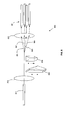
- FIG. 1 is a schematic illustration of one type of a multiple-fiber collimator that is used in various embodiments of the present invention.
- FIG. 2 is an enlarged view of a prism that is used in various embodiments of the present invention.
- FIG. 3 illustrates alternative prism configurations that may be employed in an optical switch according to various embodiments of the present invention.
- FIGS. 4A and 4B illustrate two modes of operation of a 1x2 optical switch according to an embodiment of the present invention.
- FIGS. 5A and 5B illustrate two modes of operation of a 2x4 optical switch according to an embodiment of the present invention.
- FIGS. 6A and 6B illustrate two modes of operation of a 1x2 optical switch according to another embodiment of the present invention.
- FIGS. 7A and 7B illustrate two modes of operation of a 1x2 optical switch according to another embodiment of the present invention.
- FIG. 8 illustrates various components used in a 1x4 optical switch according to an embodiment of the present invention.
- the present invention incorporates multiple-fiber collimators, also referred to as multiple-port collimators, with angle tuning elements into an optical switch in innovative ways to reduce the form factor and also to reduce costs and improve the stability and performance reliability of the optical switch design.
- optical switch may be used in various industrial applications, e.g., to provide selectable fiber routing, protection switching, system performance monitoring, etc.
- FIG. 1 is a schematic illustration of a multiple-fiber collimator 100 that is used in various embodiments of the present invention.
- the multiple-fiber collimator 100 has an optical axis 101 along which a collimating lens 110 and a multiple-fiber pigtail 120 are aligned.
- the multiple-fiber pigtail 120 has four optical fibers 131, 132, 133, 134 embedded in its body.
- the optical fibers 131, 132, 133, 134 extend axially through the body of the multiple-fiber pigtail 120 and are parallel to one another.
- Optical beams transmitted through the multiple-fiber collimator 100 cross at a point 102 that is in close proximity to the collimating lens 110 and then diverge at angles defined by the geometry of the multiple-fiber pigtail 120 and the focal length of the collimating lens 110.
- the centers of the collimating lens 110 and the multiple-fiber pigtail 120 are aligned along the optical axis 101 of the multiple-fiber collimator 100. Additional details of multiple-fiber collimators and the method of manufacturing them are disclosed in U.S. Patent 6,454,465 , entitled “Method of Making an Optical Fiber Collimating Device," and U.S. Patent 6,767,139 , entitled “Six-Port Optical Package and Method of Manufacturing.” The entire contents of both of these patents are incorporated by reference herein.
- An optical switch uses the multiple-fiber collimator 100 in combination with an angle tuning element that has a unique design.
- This unique design of the angle tuning element is based on a single-piece (monolithic) optical crystal.
- the crystal can be considered as a multiplexer of several simple prisms and/or mirrors. It deflects an optical beam into different directions or turns multiple beams into their designated directions respectively.
- Other types of angle tuning elements may be used with the present invention. In general, it may be any element that is capable of deflecting an optical beam by an angle, e.g., a mirror, an optical prism, a multiplexed prism, and the like.
- angle tuning element used in various embodiments of the present invention is a duplex prism or a roof prism, illustrated in FIG. 2. If an optical beam arrives at the upper surface of this prism, the prism will deflect the optical beam downwards by an angle ⁇ . If an optical beam arrives at the lower surface of this prism, the prism will deflect the optical beam upwards by an angle ⁇ .
- the angles ⁇ and ⁇ can be designed to be the same or different angles depending on the application. If the angles ⁇ and ⁇ are equal, the prism is considered to be symmetrical.
- FIG. 3 illustrates alternative configurations of a duplex or roof prism.
- FIGS. 4A and 4B illustrate a 1x2 optical switch 400 according to an embodiment of the present invention.
- the optical switch 400 includes an input collimator 410, an output collimator 420, and a roof prism 430 functioning as an angle tuning element.
- the input collimator 410 is a single-fiber collimator and includes a pigtail section 411 and a collimating lens 412.
- the output collimator 420 is a dual-fiber collimator and includes a pigtail section 421 and a collimating lens 422.
- the input collimator 410 and the output collimator 420 are coaxially arranged along the optical axis 401 of the optical switch 400.
- the roof prism 430 is movable into two positions by an actuator mechanism (not shown), which may be any conventional actuator, including a mechanical actuator, electromechanical actuator, magnetic actuator, piezoelectric actuator, and the like.
- FIG. 4A illustrates the optical switch 400 operating in a first mode.
- the roof prism 430 is actuated into a down position so that an optical beam transmitted through the input collimator 410 is deflected by the upper part of the roof prism 430 into one of the two fibers embedded in the pigtail section 421.
- FIG. 4B illustrates the optical switch 400 operating in a second mode. In the second mode, the roof prism 430 is actuated into an up position so that an optical beam transmitted through the input collimator 410 is deflected by the lower part of the roof prism 430 into the other fiber embedded in the pigtail section 421.
- FIGS. 5A and 5B illustrate a 2x4 optical switch 500 according to an embodiment of the present invention.
- the optical switch 500 includes an input collimator 510, an output collimator 520, and a roof prism 530 functioning as an angle tuning element.
- the input collimator 510 is a dual-fiber collimator and includes a pigtail section 511 and a collimating lens 512.
- the output collimator 520 is a four-fiber collimator and includes a pigtail section 521 and a collimating lens 522.
- the input collimator 510 and the output collimator 520 are coaxially arranged along the optical axis 501 of the optical switch 500.
- the roof prism 530 is movable into two positions by an actuator mechanism (not shown), which may be any conventional actuator, including a mechanical actuator, electromechanical actuator, magnetic actuator, piezoelectric actuator, and the like.
- FIG. 5A illustrates the optical switch 500 operating in a first mode.
- the roof prism 530 is actuated into a down position so that the optical beams 502, 503 transmitted through the input collimator 510 are deflected by the upper part of the roof prism 530 into two of the four fibers embedded in the pigtail section 521.
- FIG. 5B illustrates the optical switch 500 operating in a second mode. In the second mode, the roof prism 530 is actuated into an up position so that the optical beams 502, 503 transmitted through the input collimator 510 are deflected by the lower part of the roof prism 530 into the other two fibers embedded in the pigtail section 521.
- Embodiments of the optical switch illustrated in FIGS. 5A, 5B, 6A and 6B incorporates the highly integrated multiple-port, multiple-fiber collimators with multiplexed angle tuning elements so that they are coaxially arranged along the optical axis of the optical switch.
- an ultra compact opto-mechanical structure that is much more simple and stable relative to the prior art designs is provided.
- FIGS. 6A and 6B illustrate a 1x2 optical switch according to another embodiment of the present invention.
- input and output ports of the optical switch 600 are provided on the same side of the optical switch 600.
- This design also provides improved stability and performance reliability because it uses less components.
- a three-fiber collimator can serve as the input/output ports of a 1x2 optical switch, but in the optical switch 600, a four-fiber collimator 610 is provided because it is manufactured in higher volumes and is thus more readily available.
- the four-fiber collimator 610 includes a pigtail section 611 and a collimating lens 612.
- the optical switch 600 further includes a roof prism 630 and a mirror 640.
- the roof prism 630 is positioned in the path of the optical beam reflected by the mirror 640, but not in the path of the optical beam between the output of the collimator 610 and the mirror 640.
- the roof prism 630 may be positioned in the path of the optical beam between the output of the collimator 610 and the mirror 640, but not in the path of the optical beam reflected by the mirror 640. In either case, the roof prism 630 is movable into two positions by an actuator mechanism (not shown), which may be any conventional actuator, including a mechanical actuator, electromechanical actuator, magnetic actuator, piezoelectric actuator, and the like.
- FIG. 6A illustrates the optical switch 600 operating in a first mode.
- the roof prism 630 is actuated into a down position so that the optical beam transmitted through a first one of fibers of the four-fiber collimator 610 and the collimating lens 612 and reflected by the mirror 640 is deflected by the upper part of the roof prism 630 into a second one of the four fibers embedded in the pigtail section 611.
- FIG. 6B illustrates the optical switch 600 operating in a second mode.
- the roof prism 630 is actuated into an up position so that the optical beam transmitted through a first one of fibers of the four-fiber collimator 610 and the collimating lens 612 and reflected by the mirror 640 is deflected by the lower part of the roof prism 630 into a third one of the four fibers embedded in the pigtail section 611. A fourth one of the four fibers embedded in the pigtail section 611 is not used.
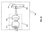
- the roof prism 630 and the mirror 640 can be replaced by a monolithic optical element 730, as shown in FIGS. 7A and 7B.
- the monolithic optical element 730 has a roof prism substrate with the two front angular surfaces having anti-reflective coating and the rear surface 731 having a high-reflective coati ng.
- FIG. 7A illustrates the optical switch 700 operating in a first mode.
- the monolithic optical element 730 is actuated into a down position so that the optical beam transmitted through a first one of fibers of the four-fiber collimator 610 and the collimating lens 612 is transmitted through the front upper surface of the monolithic optical element 730 and reflected by the rear surface of the monolithic optical element 730.
- the reflected optical beam is then deflected by the upper part of the monolithic optical element 730 into a second one of the four fibers embedded in the pigtail section 611.
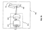
- FIG. 7B illustrates the optical switch 600 operating in a second mode.
- the monolithic optical element 730 is actuated into an up position so that the optical beam transmitted through a first one of fibers of the four-fiber collimator 610 and the collimating lens 612 is transmitted through the front lower surface of the monolithic optical element 730 and reflected by the rear surface of the monolithic optical element 730.
- the reflected optical beam is then deflected by the lower part of the monolithic optical element 730 into a third one of the four fibers embedded in the pigtail section 611.
- a fourth one of the four fibers embedded in the pigtail section 611 is not used.
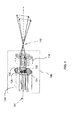
- FIG. 8 is a schematic illustration of a 1x4 optical switch 800 according to an embodiment of the present invention.
- the optical switch 800 includes an input collimator including an input fiber 811 and an input collimating lens 812, an output collimator including a set of output fibers 821 and an output collimating lens 822, and a pair of prisms 830, 840.
- the prisms 830, 840 provide two stages of angle tuning. In the first stage, the prism 830 deflects the optical beam upwards or downwards by an angle depending on its position. In the second stage, the prism 840, depending on its position, may further deflect the optical beam that has been deflected by the prism 830.
- the optical beam 851 represents an optical beam that is deflected upwards by the prism 830 and then further deflected by the prism 840.
- the optical beam 852 represents an optical beam that is deflected upwards by the prism 830 and not further deflected by the prism 840.
- the optical beam 853 represents an optical beam that is deflected downwards by the prism 830 and then further deflected by the prism 840.
- the optical beam 854 represents an optical beam that is deflected downwards by the prism 830 and not further deflected by the prism 840.
- the prisms 830, 840 are moved by an actuator mechanism (not shown), which may be any conventional actuator, including a mechanical actuator, electromechanical actuator, magnetic actuator, piezoelectric actuator, and the like.
- the prism 830 is movable into an up position where it deflects the incoming optical beam upwards and a down position where it deflects the incoming optical beam downwards.
- the prism 840 is also movable into two positions. In the first position, the prism 840 is in the path of the optical beam deflected by the prism 830. In the second position, the prism 840 is moved completely out of the path of the optical beam deflected by the prism 830.
Landscapes
- Physics & Mathematics (AREA)
- General Physics & Mathematics (AREA)
- Optics & Photonics (AREA)
- Mechanical Light Control Or Optical Switches (AREA)
Applications Claiming Priority (1)
| Application Number | Priority Date | Filing Date | Title |
|---|---|---|---|
| US11/376,051 US7286730B2 (en) | 2006-03-15 | 2006-03-15 | Optical switch having angle tuning elements and multiple-fiber collimators |
Publications (2)
| Publication Number | Publication Date |
|---|---|
| EP1837687A1 true EP1837687A1 (fr) | 2007-09-26 |
| EP1837687B1 EP1837687B1 (fr) | 2014-05-14 |
Family
ID=38137465
Family Applications (1)
| Application Number | Title | Priority Date | Filing Date |
|---|---|---|---|
| EP07103812.9A Not-in-force EP1837687B1 (fr) | 2006-03-15 | 2007-03-09 | Commutateur optique doté d'éléments de réglage d'angle et de collimateurs à fibres multiples |
Country Status (2)
| Country | Link |
|---|---|
| US (2) | US7286730B2 (fr) |
| EP (1) | EP1837687B1 (fr) |
Families Citing this family (9)
| Publication number | Priority date | Publication date | Assignee | Title |
|---|---|---|---|---|
| US8150267B1 (en) * | 2007-04-18 | 2012-04-03 | Hewlett-Packard Development Company, L.P. | Optical interconnect |
| US8611742B2 (en) * | 2011-03-15 | 2013-12-17 | Capella Photonics, Inc. | Wavelength switch system using angle multiplexing optics |
| US9164242B1 (en) * | 2012-10-16 | 2015-10-20 | Alliance Fiber Optic Products, Inc. | Variable optical power splitter |
| CN104749705A (zh) * | 2013-12-26 | 2015-07-01 | 上海伟钊光学科技股份有限公司 | 光纤传感器光路系统 |
| JP6784260B2 (ja) * | 2015-09-30 | 2020-11-11 | ソニー株式会社 | 光通信コネクタ、光通信ケーブル及び電子機器 |
| FR3060248B1 (fr) * | 2016-12-09 | 2019-03-15 | Safran Electrical & Power | Reseau de communication embarque optique en anneau pour aeronef |
| US10156677B1 (en) * | 2017-05-09 | 2018-12-18 | General Photonics Corporation | Compact optic delay lines using dual fiber collimators and roof prisms |
| JP6920978B2 (ja) * | 2017-12-18 | 2021-08-18 | 浜松ホトニクス株式会社 | 画像取得装置及び画像取得方法 |
| US12345998B2 (en) * | 2022-06-03 | 2025-07-01 | Ii-Vi Delaware, Inc. | Tunable optical wedge for reducing crosstalk in wavelength selective switch |
Citations (8)
| Publication number | Priority date | Publication date | Assignee | Title |
|---|---|---|---|---|
| EP1061389A2 (fr) | 1999-06-17 | 2000-12-20 | JDS Uniphase Inc. | Commutateur optique 1,5 x 2 |
| US6215919B1 (en) * | 1999-06-15 | 2001-04-10 | Oplink Communications, Inc. | Mechanical optical switching device |
| EP1126304A2 (fr) * | 2000-02-17 | 2001-08-22 | JDS Uniphase Inc. | Commutateur optique |
| WO2001063338A1 (fr) | 2000-02-23 | 2001-08-30 | Optical Coating Laboratory, Inc. | Commutateur de coin photometrique |
| US6437896B1 (en) | 1998-03-10 | 2002-08-20 | Vitalij Lissotschenko | Device for deviating electromagnetic rays or radiation beams in the optical spectral domain |
| US20030099430A1 (en) | 2001-11-28 | 2003-05-29 | Yiqiang Li | Reflection type compact optical switch |
| US20040013351A1 (en) * | 2002-07-22 | 2004-01-22 | Jing Zhao | Highly stable opto-mechanic switches |
| US7045005B2 (en) | 2001-07-19 | 2006-05-16 | Sumitomo Chemical Company, Limited | Ceramics dispersion liquid, method for producing the same, and hydrophilic coating agent using the same |
Family Cites Families (30)
| Publication number | Priority date | Publication date | Assignee | Title |
|---|---|---|---|---|
| JPS54103055A (en) * | 1978-01-31 | 1979-08-14 | Nippon Telegr & Teleph Corp <Ntt> | Spectrometer |
| FR2507330A1 (fr) * | 1981-06-05 | 1982-12-10 | Instruments Sa | Dispositif de commutation entre fibres optiques |
| JPS5957206A (ja) * | 1982-09-28 | 1984-04-02 | Toshiba Corp | 偏光プリズム装置 |
| US5028104A (en) * | 1987-05-21 | 1991-07-02 | Kaptron, Inc. | Fiber optics bypass switch |
| US4938555A (en) * | 1988-08-16 | 1990-07-03 | Sc Technology, Int. | Optical switch |
| US5440655A (en) * | 1993-12-29 | 1995-08-08 | At&T Corp. | Optical fiber connector bypass device and method using same |
| US5444801A (en) * | 1994-05-27 | 1995-08-22 | Laughlin; Richard H. | Apparatus for switching optical signals and method of operation |
| US6009219A (en) * | 1996-04-08 | 1999-12-28 | Axiom Analytical Incorporated | Optical beam switching device |
| US6075912A (en) * | 1998-03-17 | 2000-06-13 | Polaroid Corporation | Apparatus for coupling radiation beams into an optical waveguide |
| US6014244A (en) * | 1998-06-18 | 2000-01-11 | Hewlett-Packard Company | Multi-port optical circulator utilizing imaging lens and correction optical element |
| US6253007B1 (en) * | 1998-07-08 | 2001-06-26 | Optical Switch Corporation | Method and apparatus for connecting optical fibers |
| US6445844B1 (en) * | 1999-09-15 | 2002-09-03 | Xros, Inc. | Flexible, modular, compact fiber optic switch |
| US6628455B1 (en) * | 2000-03-03 | 2003-09-30 | Dicon Fiberoptics, Inc. | Multi-functional optical processor useful for fiberoptic applications |
| US6301048B1 (en) * | 2000-05-19 | 2001-10-09 | Avanex Corporation | Tunable chromatic dispersion and dispersion slope compensator utilizing a virtually imaged phased array |
| US6493139B1 (en) * | 2001-03-16 | 2002-12-10 | Hongdu Liu | Optical switch |
| US6597829B2 (en) * | 2001-04-27 | 2003-07-22 | Robert H. Cormack | 1xN optical fiber switch |
| US7164859B2 (en) * | 2001-08-29 | 2007-01-16 | Capella Photonics, Inc. | Free-space dynamic wavelength routing systems with interleaved channels for enhanced performance |
| US6757101B2 (en) * | 2001-10-05 | 2004-06-29 | Agiltron, Inc. | None-mechanical dual stage optical switches |
| WO2003032071A1 (fr) * | 2001-10-09 | 2003-04-17 | Xtellus Inc. | Commutateur optique selecteur de longueur d'onde |
| US6718082B2 (en) * | 2001-12-18 | 2004-04-06 | Agiltron, Inc. | Solid-State optical wavelength switches |
| US6751366B2 (en) * | 2002-02-12 | 2004-06-15 | Oplink Communications, Inc. | Multi-port circulator |
| JP4055492B2 (ja) * | 2002-07-01 | 2008-03-05 | オムロン株式会社 | 光スイッチ |
| US7095919B2 (en) * | 2002-07-12 | 2006-08-22 | Omron Corporation | Optical switch |
| EP1589678B8 (fr) * | 2003-01-31 | 2013-06-19 | Mitsubishi Denki Kabushiki Kaisha | Antenne optique |
| US7145727B2 (en) * | 2003-03-07 | 2006-12-05 | Optoplex Corporation | Unpolarized beam splitter having polarization-independent phase difference when used as an interferometer |
| US7274510B2 (en) * | 2003-03-13 | 2007-09-25 | Finisar Corporation | Circulator and polarization beam combiner |
| JP2005037659A (ja) * | 2003-07-14 | 2005-02-10 | Omron Corp | モニタリング装置 |
| TWI255933B (en) * | 2004-02-06 | 2006-06-01 | Ind Tech Res Inst | Optical polarization beam combiner |
| US7705290B2 (en) * | 2005-03-01 | 2010-04-27 | Lockheed Martin Corporation | Multi-channel fiber relays for high energy laser delivery to multi-beam optical sensors |
| US7403677B1 (en) * | 2005-05-11 | 2008-07-22 | Agiltron, Inc. | Fiberoptic reconfigurable devices with beam shaping for low-voltage operation |
-
2006
- 2006-03-15 US US11/376,051 patent/US7286730B2/en not_active Expired - Lifetime
-
2007
- 2007-03-09 EP EP07103812.9A patent/EP1837687B1/fr not_active Not-in-force
- 2007-10-19 US US11/875,533 patent/US7603006B2/en not_active Expired - Lifetime
Patent Citations (8)
| Publication number | Priority date | Publication date | Assignee | Title |
|---|---|---|---|---|
| US6437896B1 (en) | 1998-03-10 | 2002-08-20 | Vitalij Lissotschenko | Device for deviating electromagnetic rays or radiation beams in the optical spectral domain |
| US6215919B1 (en) * | 1999-06-15 | 2001-04-10 | Oplink Communications, Inc. | Mechanical optical switching device |
| EP1061389A2 (fr) | 1999-06-17 | 2000-12-20 | JDS Uniphase Inc. | Commutateur optique 1,5 x 2 |
| EP1126304A2 (fr) * | 2000-02-17 | 2001-08-22 | JDS Uniphase Inc. | Commutateur optique |
| WO2001063338A1 (fr) | 2000-02-23 | 2001-08-30 | Optical Coating Laboratory, Inc. | Commutateur de coin photometrique |
| US7045005B2 (en) | 2001-07-19 | 2006-05-16 | Sumitomo Chemical Company, Limited | Ceramics dispersion liquid, method for producing the same, and hydrophilic coating agent using the same |
| US20030099430A1 (en) | 2001-11-28 | 2003-05-29 | Yiqiang Li | Reflection type compact optical switch |
| US20040013351A1 (en) * | 2002-07-22 | 2004-01-22 | Jing Zhao | Highly stable opto-mechanic switches |
Also Published As
| Publication number | Publication date |
|---|---|
| US20070217735A1 (en) | 2007-09-20 |
| US7603006B2 (en) | 2009-10-13 |
| US7286730B2 (en) | 2007-10-23 |
| EP1837687B1 (fr) | 2014-05-14 |
| US20080037932A1 (en) | 2008-02-14 |
Similar Documents
| Publication | Publication Date | Title |
|---|---|---|
| US7603006B2 (en) | Optical switch having angle tuning elements and multiple-fiber collimators | |
| US6330102B1 (en) | Apparatus and method for 2-dimensional steered-beam NxM optical switch using single-axis mirror arrays and relay optics | |
| US6163643A (en) | Micro-mechanical variable optical attenuator | |
| US6477289B1 (en) | Optical wedge switch | |
| US6782153B2 (en) | Hybrid opto-mechanical component | |
| US20030012509A1 (en) | Switch and variable optical attenuator for single or arrayed optical channels | |
| US6404969B1 (en) | Optical switching and attenuation systems and methods therefor | |
| US6647173B2 (en) | Optical switch with a moveable optical component | |
| JP2005049742A (ja) | 可変光減衰器 | |
| US6845187B1 (en) | Linear optical beam translator for optical routing | |
| CA2334833C (fr) | Commutateur optique | |
| US6707960B2 (en) | Reflection type compact optical switch | |
| US7177498B2 (en) | Two-by-two optical routing element using two-position MEMS mirrors | |
| US7062120B2 (en) | Optical device and movable reflector | |
| CN102075824B (zh) | 在微机电系统芯片上具有集成光纤输入/输出布置的光路由机构 | |
| US6625344B2 (en) | Optical switch | |
| US6970615B1 (en) | Compact high-stability optical switches | |
| WO2004027479A1 (fr) | Dispositif de commutation du type guide d'onde optique plan utilisant des miroirs | |
| EP1531350B1 (fr) | Dispositif optique pour varier la puissance de la lumière à l'aide d'un réflecteur amovible | |
| US7106924B2 (en) | Optical switching device and optical transmission system | |
| EP1245976A1 (fr) | Configuration d'un commutateur optique | |
| US6731835B2 (en) | Optic switch | |
| WO2001063338A1 (fr) | Commutateur de coin photometrique | |
| JP2008129567A (ja) | 光デバイス | |
| US20030202739A1 (en) | Optical switch unit and a method therefore |
Legal Events
| Date | Code | Title | Description |
|---|---|---|---|
| PUAI | Public reference made under article 153(3) epc to a published international application that has entered the european phase |
Free format text: ORIGINAL CODE: 0009012 |
|
| AK | Designated contracting states |
Kind code of ref document: A1 Designated state(s): AT BE BG CH CY CZ DE DK EE ES FI FR GB GR HU IE IS IT LI LT LU LV MC MT NL PL PT RO SE SI SK TR |
|
| AX | Request for extension of the european patent |
Extension state: AL BA HR MK YU |
|
| 17P | Request for examination filed |
Effective date: 20080222 |
|
| AKX | Designation fees paid |
Designated state(s): DE FR GB IT |
|
| RAP1 | Party data changed (applicant data changed or rights of an application transferred) |
Owner name: OCLARO (NORTH AMERICA), INC. |
|
| 17Q | First examination report despatched |
Effective date: 20111108 |
|
| GRAP | Despatch of communication of intention to grant a patent |
Free format text: ORIGINAL CODE: EPIDOSNIGR1 |
|
| INTG | Intention to grant announced |
Effective date: 20131205 |
|
| RAP1 | Party data changed (applicant data changed or rights of an application transferred) |
Owner name: II-VI INCORPORATED |
|
| GRAS | Grant fee paid |
Free format text: ORIGINAL CODE: EPIDOSNIGR3 |
|
| GRAA | (expected) grant |
Free format text: ORIGINAL CODE: 0009210 |
|
| AK | Designated contracting states |
Kind code of ref document: B1 Designated state(s): DE FR GB IT |
|
| REG | Reference to a national code |
Ref country code: GB Ref legal event code: FG4D |
|
| REG | Reference to a national code |
Ref country code: DE Ref legal event code: R096 Ref document number: 602007036666 Country of ref document: DE Effective date: 20140703 |
|
| REG | Reference to a national code |
Ref country code: DE Ref legal event code: R097 Ref document number: 602007036666 Country of ref document: DE |
|
| PLBE | No opposition filed within time limit |
Free format text: ORIGINAL CODE: 0009261 |
|
| STAA | Information on the status of an ep patent application or granted ep patent |
Free format text: STATUS: NO OPPOSITION FILED WITHIN TIME LIMIT |
|
| 26N | No opposition filed |
Effective date: 20150217 |
|
| PG25 | Lapsed in a contracting state [announced via postgrant information from national office to epo] |
Ref country code: IT Free format text: LAPSE BECAUSE OF FAILURE TO SUBMIT A TRANSLATION OF THE DESCRIPTION OR TO PAY THE FEE WITHIN THE PRESCRIBED TIME-LIMIT Effective date: 20140514 |
|
| REG | Reference to a national code |
Ref country code: DE Ref legal event code: R097 Ref document number: 602007036666 Country of ref document: DE Effective date: 20150217 |
|
| REG | Reference to a national code |
Ref country code: DE Ref legal event code: R119 Ref document number: 602007036666 Country of ref document: DE |
|
| GBPC | Gb: european patent ceased through non-payment of renewal fee |
Effective date: 20150309 |
|
| REG | Reference to a national code |
Ref country code: FR Ref legal event code: ST Effective date: 20151130 |
|
| PG25 | Lapsed in a contracting state [announced via postgrant information from national office to epo] |
Ref country code: GB Free format text: LAPSE BECAUSE OF NON-PAYMENT OF DUE FEES Effective date: 20150309 Ref country code: DE Free format text: LAPSE BECAUSE OF NON-PAYMENT OF DUE FEES Effective date: 20151001 |
|
| PG25 | Lapsed in a contracting state [announced via postgrant information from national office to epo] |
Ref country code: FR Free format text: LAPSE BECAUSE OF NON-PAYMENT OF DUE FEES Effective date: 20150331 |