EP1837701A1 - Source lumineuse de surface avec guide de lumière creux pour une unité de rétroéclairage et un affichage à cristaux liquides utilisant cette unité - Google Patents
Source lumineuse de surface avec guide de lumière creux pour une unité de rétroéclairage et un affichage à cristaux liquides utilisant cette unité Download PDFInfo
- Publication number
- EP1837701A1 EP1837701A1 EP06020148A EP06020148A EP1837701A1 EP 1837701 A1 EP1837701 A1 EP 1837701A1 EP 06020148 A EP06020148 A EP 06020148A EP 06020148 A EP06020148 A EP 06020148A EP 1837701 A1 EP1837701 A1 EP 1837701A1
- Authority
- EP
- European Patent Office
- Prior art keywords
- light
- light source
- liquid crystal
- pipe
- backlight unit
- Prior art date
- Legal status (The legal status is an assumption and is not a legal conclusion. Google has not performed a legal analysis and makes no representation as to the accuracy of the status listed.)
- Withdrawn
Links
- 239000004973 liquid crystal related substance Substances 0.000 title claims abstract description 84
- 230000003287 optical effect Effects 0.000 claims description 26
- 239000000463 material Substances 0.000 claims description 18
- 238000009792 diffusion process Methods 0.000 claims description 14
- 239000002245 particle Substances 0.000 claims description 13
- 239000011347 resin Substances 0.000 claims description 11
- 229920005989 resin Polymers 0.000 claims description 11
- 239000011324 bead Substances 0.000 claims description 4
- 230000001012 protector Effects 0.000 description 8
- 238000000034 method Methods 0.000 description 6
- 239000010408 film Substances 0.000 description 5
- 229920003229 poly(methyl methacrylate) Polymers 0.000 description 5
- 239000004926 polymethyl methacrylate Substances 0.000 description 5
- 230000008901 benefit Effects 0.000 description 4
- 238000002834 transmittance Methods 0.000 description 4
- 238000003848 UV Light-Curing Methods 0.000 description 3
- 239000011248 coating agent Substances 0.000 description 3
- 238000000576 coating method Methods 0.000 description 3
- 230000000694 effects Effects 0.000 description 3
- 238000005286 illumination Methods 0.000 description 3
- 230000007423 decrease Effects 0.000 description 2
- 239000007791 liquid phase Substances 0.000 description 2
- 239000002184 metal Substances 0.000 description 2
- 229910052751 metal Inorganic materials 0.000 description 2
- 239000000203 mixture Substances 0.000 description 2
- 238000012986 modification Methods 0.000 description 2
- 230000004048 modification Effects 0.000 description 2
- 239000012788 optical film Substances 0.000 description 2
- 230000000007 visual effect Effects 0.000 description 2
- 239000004925 Acrylic resin Substances 0.000 description 1
- 229920000178 Acrylic resin Polymers 0.000 description 1
- 238000010521 absorption reaction Methods 0.000 description 1
- 239000002041 carbon nanotube Substances 0.000 description 1
- 238000004891 communication Methods 0.000 description 1
- 238000001723 curing Methods 0.000 description 1
- 230000007547 defect Effects 0.000 description 1
- 230000006866 deterioration Effects 0.000 description 1
- 238000001125 extrusion Methods 0.000 description 1
- 238000001746 injection moulding Methods 0.000 description 1
- 238000004519 manufacturing process Methods 0.000 description 1
- 150000002739 metals Chemical class 0.000 description 1
- 238000000465 moulding Methods 0.000 description 1
- 238000010137 moulding (plastic) Methods 0.000 description 1
- 239000011295 pitch Substances 0.000 description 1
- 239000004033 plastic Substances 0.000 description 1
- 229920003023 plastic Polymers 0.000 description 1
- 229920000058 polyacrylate Polymers 0.000 description 1
- 239000004417 polycarbonate Substances 0.000 description 1
- 229920000515 polycarbonate Polymers 0.000 description 1
- -1 polyethylen terephthalate Polymers 0.000 description 1
- 229920000642 polymer Polymers 0.000 description 1
- 239000011148 porous material Substances 0.000 description 1
- 229910052709 silver Inorganic materials 0.000 description 1
- 229920005992 thermoplastic resin Polymers 0.000 description 1
Images


Classifications
-
- F—MECHANICAL ENGINEERING; LIGHTING; HEATING; WEAPONS; BLASTING
- F16—ENGINEERING ELEMENTS AND UNITS; GENERAL MEASURES FOR PRODUCING AND MAINTAINING EFFECTIVE FUNCTIONING OF MACHINES OR INSTALLATIONS; THERMAL INSULATION IN GENERAL
- F16B—DEVICES FOR FASTENING OR SECURING CONSTRUCTIONAL ELEMENTS OR MACHINE PARTS TOGETHER, e.g. NAILS, BOLTS, CIRCLIPS, CLAMPS, CLIPS OR WEDGES; JOINTS OR JOINTING
- F16B37/00—Nuts or like thread-engaging members
-
- G—PHYSICS
- G02—OPTICS
- G02B—OPTICAL ELEMENTS, SYSTEMS OR APPARATUS
- G02B6/00—Light guides; Structural details of arrangements comprising light guides and other optical elements, e.g. couplings
- G02B6/0001—Light guides; Structural details of arrangements comprising light guides and other optical elements, e.g. couplings specially adapted for lighting devices or systems
- G02B6/0011—Light guides; Structural details of arrangements comprising light guides and other optical elements, e.g. couplings specially adapted for lighting devices or systems the light guides being planar or of plate-like form
- G02B6/0033—Means for improving the coupling-out of light from the light guide
- G02B6/0035—Means for improving the coupling-out of light from the light guide provided on the surface of the light guide or in the bulk of it
- G02B6/0038—Linear indentations or grooves, e.g. arc-shaped grooves or meandering grooves, extending over the full length or width of the light guide
-
- E—FIXED CONSTRUCTIONS
- E21—EARTH OR ROCK DRILLING; MINING
- E21D—SHAFTS; TUNNELS; GALLERIES; LARGE UNDERGROUND CHAMBERS
- E21D21/00—Anchoring-bolts for roof, floor in galleries or longwall working, or shaft-lining protection
- E21D21/0026—Anchoring-bolts for roof, floor in galleries or longwall working, or shaft-lining protection characterised by constructional features of the bolts
- E21D21/0033—Anchoring-bolts for roof, floor in galleries or longwall working, or shaft-lining protection characterised by constructional features of the bolts having a jacket or outer tube
-
- E—FIXED CONSTRUCTIONS
- E21—EARTH OR ROCK DRILLING; MINING
- E21D—SHAFTS; TUNNELS; GALLERIES; LARGE UNDERGROUND CHAMBERS
- E21D21/00—Anchoring-bolts for roof, floor in galleries or longwall working, or shaft-lining protection
- E21D21/0093—Accessories
-
- G—PHYSICS
- G02—OPTICS
- G02B—OPTICAL ELEMENTS, SYSTEMS OR APPARATUS
- G02B6/00—Light guides; Structural details of arrangements comprising light guides and other optical elements, e.g. couplings
- G02B6/0001—Light guides; Structural details of arrangements comprising light guides and other optical elements, e.g. couplings specially adapted for lighting devices or systems
- G02B6/0096—Light guides; Structural details of arrangements comprising light guides and other optical elements, e.g. couplings specially adapted for lighting devices or systems the lights guides being of the hollow type
-
- G—PHYSICS
- G02—OPTICS
- G02F—OPTICAL DEVICES OR ARRANGEMENTS FOR THE CONTROL OF LIGHT BY MODIFICATION OF THE OPTICAL PROPERTIES OF THE MEDIA OF THE ELEMENTS INVOLVED THEREIN; NON-LINEAR OPTICS; FREQUENCY-CHANGING OF LIGHT; OPTICAL LOGIC ELEMENTS; OPTICAL ANALOGUE/DIGITAL CONVERTERS
- G02F1/00—Devices or arrangements for the control of the intensity, colour, phase, polarisation or direction of light arriving from an independent light source, e.g. switching, gating or modulating; Non-linear optics
- G02F1/01—Devices or arrangements for the control of the intensity, colour, phase, polarisation or direction of light arriving from an independent light source, e.g. switching, gating or modulating; Non-linear optics for the control of the intensity, phase, polarisation or colour
- G02F1/13—Devices or arrangements for the control of the intensity, colour, phase, polarisation or direction of light arriving from an independent light source, e.g. switching, gating or modulating; Non-linear optics for the control of the intensity, phase, polarisation or colour based on liquid crystals, e.g. single liquid crystal display cells
- G02F1/133—Constructional arrangements; Operation of liquid crystal cells; Circuit arrangements
- G02F1/1333—Constructional arrangements; Manufacturing methods
- G02F1/1335—Structural association of cells with optical devices, e.g. polarisers or reflectors
- G02F1/1336—Illuminating devices
- G02F1/133615—Edge-illuminating devices, i.e. illuminating from the side
-
- G—PHYSICS
- G02—OPTICS
- G02B—OPTICAL ELEMENTS, SYSTEMS OR APPARATUS
- G02B6/00—Light guides; Structural details of arrangements comprising light guides and other optical elements, e.g. couplings
- G02B6/0001—Light guides; Structural details of arrangements comprising light guides and other optical elements, e.g. couplings specially adapted for lighting devices or systems
- G02B6/0011—Light guides; Structural details of arrangements comprising light guides and other optical elements, e.g. couplings specially adapted for lighting devices or systems the light guides being planar or of plate-like form
- G02B6/0033—Means for improving the coupling-out of light from the light guide
- G02B6/005—Means for improving the coupling-out of light from the light guide provided by one optical element, or plurality thereof, placed on the light output side of the light guide
- G02B6/0051—Diffusing sheet or layer
-
- G—PHYSICS
- G02—OPTICS
- G02B—OPTICAL ELEMENTS, SYSTEMS OR APPARATUS
- G02B6/00—Light guides; Structural details of arrangements comprising light guides and other optical elements, e.g. couplings
- G02B6/0001—Light guides; Structural details of arrangements comprising light guides and other optical elements, e.g. couplings specially adapted for lighting devices or systems
- G02B6/0011—Light guides; Structural details of arrangements comprising light guides and other optical elements, e.g. couplings specially adapted for lighting devices or systems the light guides being planar or of plate-like form
- G02B6/0033—Means for improving the coupling-out of light from the light guide
- G02B6/005—Means for improving the coupling-out of light from the light guide provided by one optical element, or plurality thereof, placed on the light output side of the light guide
- G02B6/0055—Reflecting element, sheet or layer
Definitions
- the present invention is directed to a surface light source device utilizing a light pipe.
- the present invention is also directed to a backlight unit and a liquid crystal display which are provided with such surface light source device.
- the liquid crystal display also know as LCD, is an electronic device that transforms electrical signals into visual signals by utilizing the change in the transmittance of the liquid crystals according to applied voltages.
- the liquid crystal display is a non-emitting display device. Therefore, the liquid crystal display needs to use an outside light source unit for illuminating the viewing plane of the liquid crystal panel from its outside in order to display visual information.
- a backlight unit is conventionally used for this use.
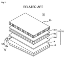
- Fig. 1 is a perspective view illustrating a liquid crystal display.
- the liquid crystal display 30 comprises a liquid crystal panel 20 and a backlight unit 10 disposed at the back of the liquid crystal panel.
- the liquid crystal panel 20 receives the light provided by the backlight unit 10 to display images.
- the backlight unit 10 comprises a light source unit 12, a light guide plate 14, a reflective sheet 16 and optical sheets 18.
- the light source unit 12 comprises a light source 12a and a light source reflector 12b.
- a cold cathode fluorescent lamp (CCFL) or an external electrode fluorescent lamp (EEFL) may be used for the light source 12a.
- the light source 12a is received inside the light source reflector 12b and disposed along one surface of the light guide plate 14.
- the light source reflector 12b is disposed outside the light source 12a to reflect the light generated at the light source 12a such that the light is input into the light guide plate 14.
- the side surface of the light guide plate 14 disposed adjacent to the light source unit 12 becomes a light incidence surface for receiving the light.
- the light generated at the light source unit 12 is input into the light guide plate 14 through the light incidence surface, and emitted through the upper surface of the light guide plate 14.
- the upper surface of the light guide plate 14 becomes the light emitting surface for emitting the light.
- the reflective sheet 16 reflects the light emitted through the lower surface of the light guide plate 14 such that the light is re-input into the inside of the light guide plate 14, which improves the light efficiency of the backlight unit 10.
- the optical sheets 18 may comprise a diffuser sheet 18a, a prism sheet 18b and a protector sheet 18c.
- the optical sheets 18a, 18b and 18c control the light such that the light is effectively provided to the viewing plane of the liquid crystal panel 20.
- the edge-light type backlight unit 10 which only uses the light that is input through the side surfaces of the light guide plate for illumination, has a problem that the light generated at the light source 12 is not fully used for illumination because the light loss occurs considerably at the light guide plate 14.
- the direct type backlight unit which has a plurality of light sources positioned directly under the liquid crystal panel, also has a problem that the light loss occurs at optical plates such as a diffusion plate.
- the light sources arranged adjacent to each other generates heat convection inside the backlight unit, and such heat convection deforms the optical sheets disposed over the light sources. The deformation of the optical sheets deteriorates the display quality.
- An object of the present invention is to provide a surface light source device that can be easily manufactured.
- Another object of the present invention is to provide a surface light source device that consumes low electric power and that is free of the heat-related problems.
- Another object of the present invention is to provide a surface light source device that is easily applicable to large size and thin display devices.
- Still further another embodiment of the present invention is to provide a backlight unit and a liquid crystal display that are provided with such surface light source device.
- the present invention provides a liquid crystal display comprising a liquid crystal panel displaying images according to electrical signals provided from the outside device; and a backlight unit for illuminating the liquid crystal panel from the back of the liquid crystal panel.
- the backlight unit comprises a surface light source device for providing surface light.
- the surface light source device includes at least one light source generating light; and at least one light pipe including an inner surface structured with a plurality of prisms, wherein the light from the light source is incident on the inner surface; and a smooth outer surface having a light emitting surface disposed substantially parallel to the liquid crystal panel, wherein the incident light is emitted through the light emitting surface; and at least one optical sheet disposed in one side of the surface light source device, wherein the optical sheet receives the light emitted from the surface light source device and provides the light to the liquid crystal panel.
- the present invention provides a backlight unit for illuminating a liquid crystal panel from the back of the liquid crystal panel.
- the backlight unit comprises a surface light source device for providing surface light.
- the surface light source device includes at least one light source generating light; and at least one light pipe including an inner surface structured with a plurality of prisms, wherein the light from the light source is incident on the inner surface; and a smooth outer surface having a light emitting surface disposed substantially parallel to the liquid crystal panel, wherein the incident light is emitted through the light emitting surface.
- the present invention provides a surface light source device for providing surface light.
- the surface light source comprises at least one light source generating light; and at least one light pipe including an inner surface structured with a plurality of prisms, wherein the light from the light source is incident on the inner surface; and a smooth outer surface having a light emitting surface disposed substantially parallel to the liquid crystal panel, wherein the incident light is emitted through the light emitting surface.
- the surface light source device can be embodied with a light pipe combined with point light sources or linear light sources. Therefore, the present invention has an advantage that the surface light source can be easily manufactured.
- the surface light source device according to the present invention uses less number of light sources. Therefore, the present invention has another advantage that the surface light source device consumes less electric power.
- the surface light source device has a structure where the light sources generating heat may be received inside the light pipe, the heat generated at the light sources is circulated only inside the light pipe and the heat is prevented from being easily transferred to the optical sheets. Therefore, the heat-related deformation of the optical sheets may be prevented.
- the surface light source device according to the present invention is easily applicable to large size and thin display devices.
- Fig. 1 is a perspective view illustrating a liquid crystal display
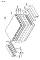
- Fig. 2a is an exploded perspective view illustrating a liquid crystal display according to one embodiment of the present invention.
- Fig. 2b is a cross-sectional view illustrating the liquid crystal display of Fig. 2a;
- Fig. 2c is a cross-sectional view illustrating the light pipe of Fig. 2b taken along the line A-A;
- Fig. 2d is an enlarged partial cross-sectional view illustrating the area C of Fig. 2c;
- Fig. 2e is a cross-sectional view illustrating a part of the liquid crystal display according to another embodiment of the present invention.
- Fig. 2f is a cross-sectional view illustrating a part of the liquid crystal display according to further another embodiment of the present invention.
- Fig. 2g is a partial cross-sectional view illustrating a part of the liquid crystal display according to still further another embodiment of the present invention.
- Fig. 3a is a cross-sectional view of the liquid crystal display according to further another embodiment of the present invention.
- Fig. 3b is a cross-sectional view of the surface light source of Fig. 3a taken along the line B-B;
- Figs. 3c and 3d are enlarged partial cross-sectional views of the area D of Fig. 3b;
- Figs. 4a-4c are cross-sectional views illustrating other embodiments of the diffusive layer and the reflector of Fig. 3b.
- Fig. 2a is an exploded perspective view illustrating a liquid crystal display according to one embodiment of the present invention
- Fig. 2b is a cross-sectional view illustrating the liquid crystal display of Fig. 2a.
- a liquid crystal panel 300 according to the present invention comprises a liquid crystal panel 200 and a backlight unit 100A.
- the liquid crystal panel 300 displays images according to driving signals and data signals provided by an outside device. To understand and work the present invention, it is not important to describe the detailed structure of the liquid crystal panel 200. And, the idea of the present invention is widely applicable to any type of liquid crystal panel usually employed in the liquid crystal display. Therefore, the structure of the liquid crystal panel 200 will not need to be herein described.
- the backlight unit 100A is positioned at the back of the liquid crystal panel 200 to provide light, for example white light to the liquid crystal panel 200.
- the backlight unit 100A comprises a surface light source device 110A for providing surface light suited to illuminating the viewing plane of the liquid crystal panel 200.
- the backlight unit 100A may comprises optical sheets 180 that are disposed between the liquid crystal panel 200 and the surface light source device 110A to transform the light provided by the surface light source device 110A to more suitable light for illuminating the liquid crystal panel 200.
- the surface light source device 110A according to one embodiment of the present invention comprises light source units 120, a light pipe 140 and a reflective sheet 160.
- Each light source unit 120 comprises light sources 120a generating the light.
- the light sources 120a according to one embodiment of the present invention are point light sources such as light emitting diodes (LEDs).
- the light sources 120a are mounted on a printed circuit board (PCB) 120b in a certain arrangement, and the outside electric power source is electrically connected to the light sources 120a through the wiring patterns of the PCB 120b.
- PCB printed circuit board
- the light sources 120a are disposed along two side surfaces. Therefore, the light generated at the light sources 120a is input into the light pipe 140 through its side surfaces.
- Each light source unit 120 comprises a housing 120c for receiving and supporting the PCB 120b mounted with the light sources 120a.
- the housing 120c may be made of metal and plastic materials, and each housing 120c has an inside groove for the PCB 120b to be inserted therein.
- the inner wall of the housing 120c has a reflective coating to reflect the light emitted from the light sources 120a.
- the two side surfaces of the light pipe 140 become light incidence surfaces through which the light generated at the light source unit 120 is input into the light pipe 140, and the upper surface of the light pipe 140 becomes the light emitting surface through which the light is output from the light pipe 140.
- the light emitting surface is preferably at least as wide as or wider than the viewing plane of the liquid crystal panel 200 so that the light is uniformly provided to the viewing plane.
- the backlight unit 100A has almost equal light efficiency to the conventional direct-lighting type backlight unit because the light pipe 140 has excellent light transportation capability and little light loss therein. Additionally, for the same level of brightness, fewer LEDs can be used in the backlight unit 100A of the present invention than in the conventional direct-lighting type backlight unit.
- the light source unit 120 may be disposed only at one side area of the light pipe 140.
- the light efficiency may be secured by installing reflecting means at the opposite side area of the light pipe 140 to reflect and reuses the light transported to the end of the light pipe 140.
- the light pipe 140 is designed to obtain uniform emitting light in such a manner that the cross-sectional area of the light pipe 140 becomes smaller along the longitudinal direction.
- Fig. 2c is a cross-sectional view illustrating the light pipe of Fig. 2b taken along the line A-A; and Fig. 2d is an enlarged partial cross-sectional view illustrating the area C of Fig. 2c.
- the inside of the light pipe 140 is hollow and filled with air, and the cross-section of the light pipe 140 is oval or rectangular.
- the light pipe 140 is a kind of hollow light waveguide.
- the light pipe 140 has a suitable structure for transporting the light input through its one or two side surfaces in a longitudinal direction.
- the inner surface 140b of the light pipe 140 is structured with micro prisms arranged in fine pitches, wherein each micro prism is extended in a longitudinal direction.
- the micro prisms can be formed as a regular triangle, a scalene triangle and an isosceles triangle, etc.
- the cross-section of each prism is preferably an isosceles triangle with 90° vertex angle.
- the outer surface of the light pipe 140 is not structured but smooth, and a part of the outer surface becomes the light emitting surface for emitting the light to the liquid crystal panel (not shown).
- the outer surface 140a of the light pipe 140 may be structured, and the inner surface 140b of the light pipe 140 may be smooth.
- both the outer and inner surfaces 140a ad 140b of the light pipe 140 may be structured.
- the distance between the outer surface 140a and the inner surface 140b varies widely according to the application circumstance. However, considering the light loss, it is preferable that the distance has a value of between 50 ⁇ 300 ⁇ m.
- the light pipe 140 is made of a thermoplastic resin that has good light transmittance, mechanical strength (especially impact resistance), thermal resistance and electrical stability.
- the light pipe 140 is made of polyethylen terephthalate (PET), polycarbonate (PC) or polymethyl methacrylate (PMMA). More preferably, the light pipe 140 is made of polymethyl methacrylate (PMMA).
- the light pipe 140 may be molded by already known plastic molding process such as injection molding or extrusion molding. It is within the capability of a person skilled in the art to make the light pipe 140 by such already known molding processes with the above mentioned materials without detailed description.
- the light pipe 140 can be made by another method where UV curing resin is coated on the polymer base film. More particularly, UV curing resin is first coated on a mold, and a base film is pressed by the mold with UV curing resin to transfer micro prism patterns on a surface of the base film. Ultraviolet ray is then irradiated over the micro prism patterns for curing, thereby to obtain an optical film having a structured surface. Finally, under applied heat, the optical film is rolled so that the light pipe 140 is obtained.
- the surface light source device 110A comprises a reflective sheet 160.
- the reflective sheet 160 reflects the light output through the lower surface of the light pipe 140 to re-input the light into the light pipe 140, thereby the light efficiency may be improved.
- the reflector sheet 180 may be manufactured by applying Ag on a sheet made of SUS, Brass, Al, PET, etc and coating it with Ti to prevent the thermal deterioration caused by heat absorption.
- the reflective sheet 160 may be obtained by dispersing micro-pores capable of scattering the light in a resin sheet such as PET.
- the backlight unit 100A may comprise a set of optical sheets 180 disposed between the surface light source device 110A and the liquid crystal panel 200.
- the set of optical sheets 180 may comprise a diffuser sheet 180a, a prism sheet 180b and a protector sheet 180c.
- the light emitted through the light emitting surface is input into the diffuser sheet 180a.
- the diffuser sheet 180a scatters the light to make the brightness uniform and widen the viewing angle.
- the prism sheet 180b is provided in the backlight unit 100A to compensate such declination of brightness.
- the prism sheet 180b refracts the light emitted from the diffuser sheet 180a in a low angle to collimate the light toward the front direction; thereby the brightness is improved within the effective viewing angle.
- the protector sheet 180c is disposed over the prism sheet 180b.
- the protector sheet 180c prevents the surface of the prism sheet 180b from being damaged, and also rewidens the viewing angle once narrowed by the prism sheet 180b.
- optical sheets 180 are not important to understand and work the present invention, and any conventional structure and material normally used in the art are widely applicable to the optical sheet 180 of the present invention.
- the light sources 120a generate light with applied electrical power.
- the light is input into the light pipe 140 through its side surfaces.
- a portion of the light input into the light pipe 140 is transported in a longitudinal direction in the light pipe 140 by the well-know phenomenon, i.e. total reflection.
- the medium which fills the inside of the light pipe 140 is air, and thus the light may be transported inside the light pipe 140 with little or no loss.
- the light input into the light pipe 140 is emitted through the outer surface of the light pipe 140 while transported inside the light pipe 140.
- the light emitted through the lower surface of the light pipe 140 is reflected on the reflective sheet 160 and re-input into the light pipe 140, whereas the light emitted through the upper surface of the light pipe 140, i.e. the light emitting surface is provided to the liquid crystal panel 200 through the optical sheets 180.
- the light emitted through the light emitting surface is first input into the diffuser sheet 180a.
- the diffuser sheet 180a scatters the light to make the brightness uniform and widen the viewing angle.
- the light is input to the prism sheet 180b through the diffuser sheet 180a, and the prism sheet 180b refracts the light emitted from the diffuser sheet 180a in a low angle to collimate the light toward the front direction.
- the light is input into the protector sheet 180c through the prism sheet 180b, and the viewing angle once narrowed while passing through the prism sheet 180b is re-widened by the protector sheet 180c to be input into the liquid crystal panel 200.
- the liquid crystal panel 200 modulates the arrangement of the liquid crystal molecules and controls its light transmittance to display images.
- Fig. 2e is a cross-sectional view illustrating a part of the liquid crystal display according to another embodiment of the present invention.
- Fig. 2f is a cross-sectional view illustrating a part of the liquid crystal display according to further another embodiment of the present invention.
- Fig. 2g is a partial cross-sectional view illustrating a part of the liquid crystal display according to still further another embodiment of the present invention. For the convenience, the same parts as those of the foregoing embodiment are not illustrated.
- LEDs in the form of point light sources are employed for the lights sources 120a.
- the linear light sources such as CCFLs or EEFLs may be employed for the light sources 120a.
- the linear light sources 130 are disposed adjacent to each other inside the light pipe 140.
- the light sources 130 can be disposed along two side surfaces of the light pipe 140. Therefore, the light generated at the light sources 130 is input into the light pipe 140 through its side surfaces.
- the surface light source device 110A is embodied with one light pipe 140.
- the surface light source device 110A may be also embodied with a plurality of light pipes 140 disposed in such a manner that the adjacent light pipes 140 contact each other.
- Such simple disposition of the light pipes 140 allows the optical communication between the light pipes 140 because each light pipe 140 has the same dimension.
- Fig. 3a is a cross-sectional view of the liquid crystal display according to further another embodiment of the present invention
- Fig. 3b is a cross-sectional view of the surface light source of Fig. 3a taken along the line B-B
- Figs. 3c and 3d are enlarged partial cross-sectional views of the area D of Fig. 3b.
- the liquid crystal display 400 comprises the liquid crystal panel 200 and a backlight unit 100B.
- the backlight unit 100B comprises a surface light source device 110B for providing surface light.
- the backlight unit 100B may optionally comprise the optical sheets 180 to transform the light provided by the surface light source device 110B to more suitable light for the illumination of the panel 200.
- the surface light source device 110B comprises the light source units 120, the light pipe 140, a diffusive layer 142 disposed outside the light pipe and a reflector 144 disposed inside the light pipe 140.
- the diffusive layer 142 enables the light confined inside the light pipe 140 to be emitted outside the light pipe 140 and scatters the light for brightness uniformity.
- the diffusive layer 142 comprises a base material 142b consisting of a resin and a plurality of diffusion particles 142a and 142a' distributed in the base material 142b.
- the base material 142b is preferably an acrylic resin that has good light transmittance, thermal resistance and mechanical strength. More preferably, the bases material 142b is polyacrylate or polymethyl methacrylate.
- Beads consisting of the same or other resins as the base material 142b may be used for the diffusion particles 142a and 142a'.
- the diffusion particles 142a and 142a' are preferably contained by 25-35wt% against the base material 142b. More preferably, the diffusion particles 142a and 142a' are contained by 30wt% against the base material 142b.
- the size and the distribution of the diffusion particles 142a are random. Such random structure increases the haze effect to prevent the defects such as scratches that physical contacts would make on the base material 142b or the diffuser sheet (130a of Fig. 3) from being projected onto the liquid crystal panel (200 of Fig. 3a).
- the size and the distribution of the diffusion particle 142a' are substantially uniform. Such uniform structure allows the brightness to increase although the haze effect rather decreases. In general, as the uniformity of the diffusion particles 142a' increases, the haze effect decreases but the brightness increases.
- the diffusive layer 142 can be formed by various methods already known in the art.
- the diffusive layer 142 can be obtained by a method where diffusion particles such as beads are mixed with a liquid phase resin and the mixture is applied to a base film, followed by the mixture being cured; and the film is thermo-compressed onto the outside surface of the light pipe 140.
- the diffusive layer 142 can be obtained by another method where a liquid phase resin with bead distributed therein is applied to the outside surface of the light pipe 140.
- the reflector 144 is disposed inside the light pipe 140.
- the reflector 144 prevents the light from being emitted through the lower surface of the light pipe 140 and thus improves the light efficiency. Furthermore, the reflector 144 enables the light confined in the light pipe 140 to be emitted outside the light pipe 140.
- the reflector 144 may consist of high reflective materials.
- the reflector 144 comprises a reflective coating consisting of metals such as Al or Ag.
- the optical sheets 180 are disposed between the liquid crystal panel 200 and the surface light source device 110B, and the optical sheets 180 may comprise the diffuser sheet 180a, the prism sheet 180b and the protector sheet 180c.
- the light sources 120a generate light with applied electrical power.
- the light is input into the light pipe 140 through its side surfaces.
- a portion of the light input into the light pipe 140 is transported in a longitudinal direction in the light pipe 140 by the well-know phenomenon, i.e. total reflection.
- the medium which fills the inside of the light pipe 140 is air, and thus the light may be transported inside the light pipe 140 with little or no loss.
- the light is reflected on the upper surface of the reflector 144 while transported inside the light pipe 140, and the reflected light is input into the diffusive layer 142.
- the inputted light is scattered and unified by the diffusion particles (142a and 142a' of Figs. 3a and 3b) distributed in the diffusive layer 142.
- the light passing though the diffusive layer 142 is inputted into the liquid crystal panel 200 through the diffuser sheet 180a, the prism sheet 180b and the protector sheet 180c.
- the diffusive layer 142 fully covers the outer surface of the light pipe 140, and the reflector 144 is inserted in the light pipe 140.
- the structure and disposition of the diffusive layer 142 and the reflector 144 can be modified variously by a person skilled in the art. Hereinafter, some modifications of the diffusive layer 142 and the reflector 144 will be described with reference to the drawings.
- Figs. 4a-4c are cross-sectional views illustrating other embodiments of the diffusive layer and the reflector of Fig. 3b. Only, the structural differences from the diffusive layer 142 and the reflector 144 are mainly described for convenience.
- the diffusive layer 142 is disposed to fully cover the outside surface of the light pipe 140, and the reflector 244 is disposed on the lower surface of the diffusive layer 142 as shown in the drawing.
- the diffusive layer 342 and the reflector 344 both are disposed only on a certain area of the outer surface of the light pipe 140.
- the diffusive layer 342 is formed at the position facing the liquid crystal panel (not shown), and the reflector 344 is disposed on the lower surface of the light pipe 140 and faces the diffusive layer 342 with the light pipe 140 therebetween.
- the diffusive layer 442 is formed to fully cover the outer surface of the light pipe 440, and the reflector 444 is disposed in the light pipe 440. Only, in this case, the inside area of the light pipe 440 where the reflector 444 is disposed is free of the micro prism structure.
Landscapes
- Physics & Mathematics (AREA)
- Engineering & Computer Science (AREA)
- Optics & Photonics (AREA)
- General Physics & Mathematics (AREA)
- Nonlinear Science (AREA)
- Mining & Mineral Resources (AREA)
- Mathematical Physics (AREA)
- Structural Engineering (AREA)
- Geochemistry & Mineralogy (AREA)
- General Life Sciences & Earth Sciences (AREA)
- Life Sciences & Earth Sciences (AREA)
- Chemical & Material Sciences (AREA)
- Crystallography & Structural Chemistry (AREA)
- Geology (AREA)
- General Engineering & Computer Science (AREA)
- Mechanical Engineering (AREA)
- Liquid Crystal (AREA)
- Planar Illumination Modules (AREA)
- Light Guides In General And Applications Therefor (AREA)
- Optical Elements Other Than Lenses (AREA)
- Devices For Indicating Variable Information By Combining Individual Elements (AREA)
Applications Claiming Priority (1)
| Application Number | Priority Date | Filing Date | Title |
|---|---|---|---|
| KR1020060026962A KR20070096457A (ko) | 2006-03-24 | 2006-03-24 | 광 파이프를 이용한 면 광원 장치, 이를 구비한 백라이트유닛 및 액정 표시 장치 |
Publications (1)
| Publication Number | Publication Date |
|---|---|
| EP1837701A1 true EP1837701A1 (fr) | 2007-09-26 |
Family
ID=37944195
Family Applications (1)
| Application Number | Title | Priority Date | Filing Date |
|---|---|---|---|
| EP06020148A Withdrawn EP1837701A1 (fr) | 2006-03-24 | 2006-09-26 | Source lumineuse de surface avec guide de lumière creux pour une unité de rétroéclairage et un affichage à cristaux liquides utilisant cette unité |
Country Status (6)
| Country | Link |
|---|---|
| US (1) | US20070223245A1 (fr) |
| EP (1) | EP1837701A1 (fr) |
| JP (1) | JP5089960B2 (fr) |
| KR (1) | KR20070096457A (fr) |
| CN (1) | CN100549782C (fr) |
| TW (1) | TWI347474B (fr) |
Cited By (8)
| Publication number | Priority date | Publication date | Assignee | Title |
|---|---|---|---|---|
| WO2009100307A1 (fr) * | 2008-02-07 | 2009-08-13 | 3M Innovative Properties Company | Rétroéclairage creux comportant des films structurés |
| CN102374455A (zh) * | 2010-08-18 | 2012-03-14 | Lg伊诺特有限公司 | 背光单元和使用该背光单元的显示设备 |
| US8469575B2 (en) | 2007-05-20 | 2013-06-25 | 3M Innovative Properties Company | Backlight and display system using same |
| US8523419B2 (en) | 2007-05-20 | 2013-09-03 | 3M Innovative Properties Company | Thin hollow backlights with beneficial design characteristics |
| US8608363B2 (en) | 2007-05-20 | 2013-12-17 | 3M Innovative Properties Company | Recycling backlights with semi-specular components |
| US8757858B2 (en) | 2008-06-04 | 2014-06-24 | 3M Innovative Properties Company | Hollow backlight with tilted light source |
| US9028108B2 (en) | 2007-05-20 | 2015-05-12 | 3M Innovative Properties Company | Collimating light injectors for edge-lit backlights |
| US9541698B2 (en) | 2008-02-22 | 2017-01-10 | 3M Innovative Properties Company | Backlights having selected output light flux distributions and display systems using same |
Families Citing this family (8)
| Publication number | Priority date | Publication date | Assignee | Title |
|---|---|---|---|---|
| TW201011415A (en) * | 2008-09-15 | 2010-03-16 | Chunghwa Picture Tubes Ltd | Light source set and back light module |
| WO2010083074A2 (fr) | 2009-01-15 | 2010-07-22 | 3M Innovative Properties Company | Bloc lumineux |
| TWI395021B (zh) * | 2009-07-02 | 2013-05-01 | 瀚宇彩晶股份有限公司 | 液晶顯示器之背光模組 |
| KR101830718B1 (ko) * | 2011-07-15 | 2018-02-22 | 엘지이노텍 주식회사 | 디스플레이 장치 |
| KR101339885B1 (ko) * | 2012-06-08 | 2013-12-10 | 주식회사 한광 | 광학조명필름이 내장된 광파이프조명장치 |
| JP2016033860A (ja) * | 2014-07-31 | 2016-03-10 | 株式会社ソフケン | 照明装置 |
| US20160154174A1 (en) * | 2014-12-02 | 2016-06-02 | Shenzhen China Star Optoelectronics Technology Co., Ltd. | Light guide plate, backlight module, and liquid crystal display device |
| JP6512201B2 (ja) * | 2016-09-30 | 2019-05-15 | 日亜化学工業株式会社 | 線状発光装置の製造方法及び線状発光装置 |
Citations (4)
| Publication number | Priority date | Publication date | Assignee | Title |
|---|---|---|---|---|
| US5863114A (en) * | 1993-03-09 | 1999-01-26 | Fujitsu Limited | Light emissive panel unit |
| JPH11142845A (ja) * | 1997-11-07 | 1999-05-28 | Toshiba Corp | バックライトユニットおよびこれを備えた液晶表示装置 |
| WO2002008663A2 (fr) * | 2000-07-26 | 2002-01-31 | 3M Innovative Properties Company | Illuminateur a surface creuse |
| US20060013015A1 (en) * | 2002-05-23 | 2006-01-19 | Kazuyuki Hashimoto | Surface light-emitting device |
Family Cites Families (9)
| Publication number | Priority date | Publication date | Assignee | Title |
|---|---|---|---|---|
| JP2673323B2 (ja) * | 1991-08-29 | 1997-11-05 | 日本写真印刷株式会社 | 面光源装置の導光板とその製造方法 |
| US5359691A (en) * | 1992-10-08 | 1994-10-25 | Briteview Technologies | Backlighting system with a multi-reflection light injection system and using microprisms |
| JP3311822B2 (ja) * | 1993-06-14 | 2002-08-05 | 日本ケミテック株式会社 | 中空導光板本体及びそれを用いた中空導光板 |
| JP3280828B2 (ja) * | 1995-06-30 | 2002-05-13 | 富士通化成株式会社 | バックライトユニット |
| US6031958A (en) * | 1997-05-21 | 2000-02-29 | Mcgaffigan; Thomas H. | Optical light pipes with laser light appearance |
| TW500962B (en) * | 1999-11-26 | 2002-09-01 | Sanyo Electric Co | Surface light source and method for adjusting its hue |
| JP2001312213A (ja) * | 2000-04-26 | 2001-11-09 | Internatl Business Mach Corp <Ibm> | バックライトユニット、液晶表示装置、ならびに導光板の製造方法 |
| US6809892B2 (en) * | 2000-07-26 | 2004-10-26 | 3M Innovative Properties Company | Hollow surface illuminator |
| JP3948625B2 (ja) * | 2003-11-26 | 2007-07-25 | 大日本印刷株式会社 | レンズシートを用いた面光源 |
-
2006
- 2006-03-24 KR KR1020060026962A patent/KR20070096457A/ko not_active Ceased
- 2006-09-26 EP EP06020148A patent/EP1837701A1/fr not_active Withdrawn
- 2006-09-28 US US11/528,583 patent/US20070223245A1/en not_active Abandoned
- 2006-09-29 CN CNB2006101419037A patent/CN100549782C/zh not_active Expired - Fee Related
- 2006-10-05 TW TW095137092A patent/TWI347474B/zh not_active IP Right Cessation
- 2006-11-07 JP JP2006301529A patent/JP5089960B2/ja not_active Expired - Fee Related
Patent Citations (4)
| Publication number | Priority date | Publication date | Assignee | Title |
|---|---|---|---|---|
| US5863114A (en) * | 1993-03-09 | 1999-01-26 | Fujitsu Limited | Light emissive panel unit |
| JPH11142845A (ja) * | 1997-11-07 | 1999-05-28 | Toshiba Corp | バックライトユニットおよびこれを備えた液晶表示装置 |
| WO2002008663A2 (fr) * | 2000-07-26 | 2002-01-31 | 3M Innovative Properties Company | Illuminateur a surface creuse |
| US20060013015A1 (en) * | 2002-05-23 | 2006-01-19 | Kazuyuki Hashimoto | Surface light-emitting device |
Cited By (14)
| Publication number | Priority date | Publication date | Assignee | Title |
|---|---|---|---|---|
| US8740442B2 (en) | 2007-05-20 | 2014-06-03 | 3M Innovative Properties Company | Backlight and display system using same |
| US9028108B2 (en) | 2007-05-20 | 2015-05-12 | 3M Innovative Properties Company | Collimating light injectors for edge-lit backlights |
| US9091408B2 (en) | 2007-05-20 | 2015-07-28 | 3M Innovative Properties Company | Recycling backlights with semi-specular components |
| US8469575B2 (en) | 2007-05-20 | 2013-06-25 | 3M Innovative Properties Company | Backlight and display system using same |
| US8523419B2 (en) | 2007-05-20 | 2013-09-03 | 3M Innovative Properties Company | Thin hollow backlights with beneficial design characteristics |
| US8608363B2 (en) | 2007-05-20 | 2013-12-17 | 3M Innovative Properties Company | Recycling backlights with semi-specular components |
| US8926159B2 (en) | 2007-05-20 | 2015-01-06 | 3M Innovative Properties Company | Thin hollow backlights with beneficial design characteristics |
| JP2011514624A (ja) * | 2008-02-07 | 2011-05-06 | スリーエム イノベイティブ プロパティズ カンパニー | 構造化フィルムを有する中空のバックライト |
| US8848132B2 (en) | 2008-02-07 | 2014-09-30 | 3M Innovative Properties Company | Hollow backlight with structured films |
| WO2009100307A1 (fr) * | 2008-02-07 | 2009-08-13 | 3M Innovative Properties Company | Rétroéclairage creux comportant des films structurés |
| US9541698B2 (en) | 2008-02-22 | 2017-01-10 | 3M Innovative Properties Company | Backlights having selected output light flux distributions and display systems using same |
| US8757858B2 (en) | 2008-06-04 | 2014-06-24 | 3M Innovative Properties Company | Hollow backlight with tilted light source |
| CN102374455B (zh) * | 2010-08-18 | 2016-01-20 | Lg伊诺特有限公司 | 背光单元和使用该背光单元的显示设备 |
| CN102374455A (zh) * | 2010-08-18 | 2012-03-14 | Lg伊诺特有限公司 | 背光单元和使用该背光单元的显示设备 |
Also Published As
| Publication number | Publication date |
|---|---|
| JP5089960B2 (ja) | 2012-12-05 |
| TW200736725A (en) | 2007-10-01 |
| CN100549782C (zh) | 2009-10-14 |
| KR20070096457A (ko) | 2007-10-02 |
| TWI347474B (en) | 2011-08-21 |
| JP2007256910A (ja) | 2007-10-04 |
| US20070223245A1 (en) | 2007-09-27 |
| CN101042497A (zh) | 2007-09-26 |
Similar Documents
| Publication | Publication Date | Title |
|---|---|---|
| US7710512B2 (en) | Prism sheet, backlight unit and liquid crystal display | |
| CN101122714B (zh) | 光导板和具有光导板的液晶显示装置 | |
| CN1828388B (zh) | 背光单元以及使用其的液晶显示器件 | |
| EP1837701A1 (fr) | Source lumineuse de surface avec guide de lumière creux pour une unité de rétroéclairage et un affichage à cristaux liquides utilisant cette unité | |
| US7649590B2 (en) | Backlight assembly and liquid crystal display having the same | |
| CN100501528C (zh) | 具有散热层的背光单元、具有散热层的显示设备以及用于制造散热层的方法 | |
| US8049837B2 (en) | Multilayer film, backlight unit and liquid crystal display having the same | |
| US20070086191A1 (en) | Optical member, method of manufacturing the optical member, and display device having the optical member | |
| US20080049441A1 (en) | Surface light source device, backlight unit and liquid crystal display having the same | |
| US20060291253A1 (en) | Light-guide plate, backlight assembly and liquid crystal display device having the same | |
| KR20010046581A (ko) | 표시 장치용 백라이트 장치 | |
| US20070091642A1 (en) | Light guide plate and backlight unit having the same | |
| CN100383640C (zh) | 直下式背光模组 | |
| KR100750995B1 (ko) | 광 파이프를 이용한 면 광원 장치, 이를 구비한 백라이트유닛 및 액정 표시 장치 | |
| KR100827380B1 (ko) | 광 파이프를 이용한 면 광원 장치, 이를 구비한 백라이트유닛 및 액정 표시 장치 | |
| KR100801021B1 (ko) | 발광 다이오드와 광 파이프를 이용한 백라이트 유닛 및이를 구비한 액정표시장치 | |
| KR20070040957A (ko) | 반사 입자를 포함하는 프리즘 시트 및 이를 포함하는백라이트 유닛 | |
| KR101054822B1 (ko) | 광파이프를 이용한 면광원장치, 이를 구비한 백라이트 유닛및 액정표시장치 | |
| TWI281070B (en) | Backlight moduld | |
| KR20080045521A (ko) | 백라이트 유닛과 이를 갖는 디스플레이장치 | |
| KR20090089969A (ko) | 광학필름, 이를 구비한 백라이트 유닛 및 액정표시장치 | |
| KR20090089968A (ko) | 광학필름, 이를 구비한 백라이트 유닛 및 액정표시장치 | |
| KR100829696B1 (ko) | 백라이트 유닛 및 이를 구비한 액정표시장치 | |
| CN1716047A (zh) | 平面光源装置 | |
| KR20080029550A (ko) | 액정표시장치 |
Legal Events
| Date | Code | Title | Description |
|---|---|---|---|
| PUAI | Public reference made under article 153(3) epc to a published international application that has entered the european phase |
Free format text: ORIGINAL CODE: 0009012 |
|
| 17P | Request for examination filed |
Effective date: 20060926 |
|
| AK | Designated contracting states |
Kind code of ref document: A1 Designated state(s): AT BE BG CH CY CZ DE DK EE ES FI FR GB GR HU IE IS IT LI LT LU LV MC NL PL PT RO SE SI SK TR |
|
| AX | Request for extension of the european patent |
Extension state: AL BA HR MK YU |
|
| 17Q | First examination report despatched |
Effective date: 20071214 |
|
| AKX | Designation fees paid |
Designated state(s): DE FR GB NL |
|
| RAP1 | Party data changed (applicant data changed or rights of an application transferred) |
Owner name: LG ELECTRONICS, INC. |
|
| GRAP | Despatch of communication of intention to grant a patent |
Free format text: ORIGINAL CODE: EPIDOSNIGR1 |
|
| INTG | Intention to grant announced |
Effective date: 20150810 |
|
| STAA | Information on the status of an ep patent application or granted ep patent |
Free format text: STATUS: THE APPLICATION IS DEEMED TO BE WITHDRAWN |
|
| 18D | Application deemed to be withdrawn |
Effective date: 20151222 |