EP1837718A1 - Hemmungsvorrichtung für Uhrwerke - Google Patents
Hemmungsvorrichtung für Uhrwerke Download PDFInfo
- Publication number
- EP1837718A1 EP1837718A1 EP06005703A EP06005703A EP1837718A1 EP 1837718 A1 EP1837718 A1 EP 1837718A1 EP 06005703 A EP06005703 A EP 06005703A EP 06005703 A EP06005703 A EP 06005703A EP 1837718 A1 EP1837718 A1 EP 1837718A1
- Authority
- EP
- European Patent Office
- Prior art keywords
- blocker
- rest
- ellipse
- exhaust device
- escape wheel
- Prior art date
- Legal status (The legal status is an assumption and is not a legal conclusion. Google has not performed a legal analysis and makes no representation as to the accuracy of the status listed.)
- Granted
Links
- 230000007935 neutral effect Effects 0.000 claims abstract description 6
- 230000002093 peripheral effect Effects 0.000 claims description 8
- 238000006073 displacement reaction Methods 0.000 claims description 3
- 239000010980 sapphire Substances 0.000 claims description 2
- 229910052594 sapphire Inorganic materials 0.000 claims description 2
- 239000002969 artificial stone Substances 0.000 claims 1
- 239000010437 gem Substances 0.000 claims 1
- 230000001174 ascending effect Effects 0.000 description 2
- 230000010355 oscillation Effects 0.000 description 2
- 230000035939 shock Effects 0.000 description 2
- 230000005540 biological transmission Effects 0.000 description 1
- 239000000470 constituent Substances 0.000 description 1
- 239000000314 lubricant Substances 0.000 description 1
- 238000005461 lubrication Methods 0.000 description 1
- 238000004519 manufacturing process Methods 0.000 description 1
Images





Classifications
-
- G—PHYSICS
- G04—HOROLOGY
- G04B—MECHANICALLY-DRIVEN CLOCKS OR WATCHES; MECHANICAL PARTS OF CLOCKS OR WATCHES IN GENERAL; TIME PIECES USING THE POSITION OF THE SUN, MOON OR STARS
- G04B17/00—Mechanisms for stabilising frequency
- G04B17/20—Compensation of mechanisms for stabilising frequency
- G04B17/28—Compensation of mechanisms for stabilising frequency for the effect of imbalance of the weights, e.g. tourbillon
- G04B17/285—Tourbillons or carrousels
-
- G—PHYSICS
- G04—HOROLOGY
- G04B—MECHANICALLY-DRIVEN CLOCKS OR WATCHES; MECHANICAL PARTS OF CLOCKS OR WATCHES IN GENERAL; TIME PIECES USING THE POSITION OF THE SUN, MOON OR STARS
- G04B15/00—Escapements
- G04B15/06—Free escapements
Definitions
- the subject of the present invention is an escapement device for a watch movement, in particular for a wristwatch or a pocket watch, the clockwork movement possibly comprising a tourbillon or not.
- the object of the invention is to provide a simple manufacturing exhaust device, to reduce shocks and friction to increase the efficiency and reduce or eliminate the lubrication of the device.
- the exhaust system according to the present invention is distinguished by the features listed in claim 1.
- the axis of balance 3 carries a plate 4 provided with a pulse lift 5 extending substantially radially and whose end protrudes from the periphery of the plate 4.
- This plate 4 further comprises near its periphery a release pin 6 extending perpendicularly to the plane of the plate 4 in the direction opposite to the balance 1.
- a spiral spring 7 is fixed by its inner end to the balance shaft 3 and its outer end 7a to a stud 8 fixed on a bridge or the plate of the movement (not shown) or on the cage of a whirlwind if exhaust is mounted in a whirlpool.
- the axis of the balance 3 is pivoted between a bridge and the plate of the movement or between the cage and a bridge of a tourbillon.
- the exhaust device further comprises an escape wheel 11 and its pinion 12 pivoted between the plate and a bridge of the movement and positioned such that each tooth of the escape wheel 11 can be placed on the path of the pulse lift 5 to give the pulses to the balance 1.
- the exhaust device further comprises a blocker 13 pivoted between the movement plate and a star bridge 14.
- This blocker 13 comprises a release lever 15 extending towards the plate 4 and can be actuated by the release pin 6 of this tray 4.
- the blocker 13 also comprises a rest ellipse 16 having the general shape of a cylinder provided with a plate 16a and extending perpendicularly to the plane of the blocker 13, the ellipse comprises a first part or end extending in the opposite direction the pendulum and a second portion or end extending in the direction of the pendulum.
- the rest ellipse 16 is constructed of sapphire.
- the ends of this rest ellipse are pivoted in fixed bearings 17, one carried by the star bridge 14 and the other by the platen of the movement.
- the star bridge 14 comprises two stops 18, 18a making it possible to limit the angular displacements of the blocker 13.
- the exhaust device further comprises a positioning arm 19 whose free end cooperates with the plane face 16a of the rest ellipse 16 and more particularly with the first part or end of the rest ellipse, to hold the blocker 13 in neutral position of rest.
- This positioning arm 19 is pivoted on the platen of the movement and subjected to the action of a spiral return spring 20 tending to apply its free end against the flat face 16a of the rest ellipse 16.
- the restoring force of this spiral return spring 20 is weak, just sufficient to replace the blocker 13 in its neutral position after it has been angularly displaced by the release pin 10 of the plate 4 coming into contact with the release lever 15 of the blocker during the pendulum oscillations 1.
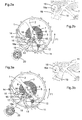
- Figures 2a and 2b illustrate the exhaust device at the moment when the balance 1 having completed its upward stroke, reverses its direction of rotation and begins its downward stroke for which it moves in the counterclockwise direction following the arrow F1. While the rocker 1 describes the additional arc in the downward period of the alternation, the escape wheel 11 is stopped by one of its teeth which is pressed against the cylindrical portion of the rest ellipse 16 of the blocker 13 and more particularly against the second part or end of the rest ellipse which is in its neutral rest position. The blocker 13 is held in this rest position by the arm 19 whose free end is applied against the flat face 16a of the rest ellipse 16 of the blocker 13.
- This arm 19 exerts a pressure, the lowest possible, thanks to the hairspring 20 fixed on the axis of rotation of the arm 19.
- the torque exerted by this spiral spring 20 on the arm 19 is adjustable with a mobile peg holder on the plate to which is fixed the other end of the spring 19.
- the release pin 6 is integral with the balance 1 by its driving on the plate 4, perpendicular to the pulse lift 5 and angularly offset relative thereto.
- the pendulum 1 thus moves in the counter-clockwise direction to the so-called "lost blow” phase illustrated in FIGS. 3a, 3b and 4a, 4b.
- the release pin 6 touches the end of the release lever 15 of the blocker 13 which causes a slight movement of the blocker 13 only in the clockwise direction.
- the escape wheel 11 does not undergo any geometric recoil during this phase of the "lost blow” because it rests with one of its teeth on the cylindrical portion of the rest ellipse 16 of the blocker 13 which is concentric with the axis This causes only a very low friction between a tooth of the escape wheel 11 and the rest ellipse 16 of the blocker 13.
- the pendulum 1 continues its downward movement then stops and begins its ascending phase clockwise along the arrow F2 to the position shown in Figures 5a and 5b.
- the release pin 6 comes into contact with the release lever 15 of the blocker 13 which has repositioned in the rest position under the action of the arm 19.
- the release pin 6 moves the blocker counterclockwise and simultaneously lifting pulse 5 is placed on the path of a tooth of the escape wheel 11.
- the stroke in the counterclockwise direction of the blocker 13 is stopped by the abutment 18a of the star bridge 14 and at this moment the tooth of the escape wheel 11 leaves the cylindrical wall 16 of the rest ellipse 16 which is thus released (FIGS. 6a, 6b and 7a, 7b).
- the escape wheel 11 is thus released thanks to the flat face 16a of the rest ellipse 16 of the blocker.
- another tooth of the escape wheel 11 collides with the pulse lift 5 of the plate 4 driven on the axis 3 of the balance 1 (FIG. 8).
- the arm 19 of the blocker 13 reposition the blocker 13 in the neutral rest position to allow the next tooth, the one that gave the impulse, of the escape wheel 11 to stop against the cylindrical peripheral surface. of the rest ellipse 16 of the blocker 13.
- this escapement device is a free escapement since it leaves the balance with complete freedom to traverse the additional arcs with the functions of the escapement. It is also a direct impulse escapement because it does not include an intermediate energy transmission system as is the case for anchor escapements.
- the four bodies of this exhaust system are:
- the plate 4 integral with the balance 1, with the pulse pallet 5 and the release pin 6.
- the impetus given by the escape wheel 11 is directly transmitted to the balance 1. This makes it possible to reduce shocks and friction and thus to increase the efficiency. This escapement also has the distinction of transmitting only one pulse per complete cycle (two alternations).
- the peripheral surface of the rest ellipse 16 could have various shapes provided that it comprises a first portion to stop the teeth of the escape wheel when the blocker 13 is in certain positions and a second portion to release the teeth of the escape wheel when the blocker 13 is in other positions as described above.
- the first portion is rounded and it is all the more preferable that it be cylindrical so that the friction between a tooth of the escape wheel and the ellipse when the blocker rotates is very low.
- the second portion of the peripheral surface of the rest ellipse 16 is flat.
- the peripheral surface of the first end of the ellipse must include a portion (preferably flat once more) to properly cooperate with the positioning arm 19 in the manner described above.
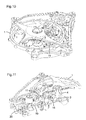
- FIGS. 10 to 13 represent, by way of example, the exhaust device described above mounted in a tourbillon cage whose center of rotation lies on the axis of the blocker 13 and not on the axis of the balance 1.
- Figure 11 is a section of the vortex showing the principle of inverted pivoting of the blocker on a fixed pivot.
- Figure 12 is a top view of the tourbillon cage while Figure 13 is a bottom view where we see the drive of the cage performed by an internal toothing performed on the second fixed wheel 21.
Landscapes
- Physics & Mathematics (AREA)
- General Physics & Mathematics (AREA)
- Mechanical Operated Clutches (AREA)
Priority Applications (1)
| Application Number | Priority Date | Filing Date | Title |
|---|---|---|---|
| EP20060005703 EP1837718B1 (de) | 2006-03-21 | 2006-03-21 | Hemmungsvorrichtung für Uhrwerke |
Applications Claiming Priority (1)
| Application Number | Priority Date | Filing Date | Title |
|---|---|---|---|
| EP20060005703 EP1837718B1 (de) | 2006-03-21 | 2006-03-21 | Hemmungsvorrichtung für Uhrwerke |
Publications (2)
| Publication Number | Publication Date |
|---|---|
| EP1837718A1 true EP1837718A1 (de) | 2007-09-26 |
| EP1837718B1 EP1837718B1 (de) | 2014-05-28 |
Family
ID=37564114
Family Applications (1)
| Application Number | Title | Priority Date | Filing Date |
|---|---|---|---|
| EP20060005703 Expired - Lifetime EP1837718B1 (de) | 2006-03-21 | 2006-03-21 | Hemmungsvorrichtung für Uhrwerke |
Country Status (1)
| Country | Link |
|---|---|
| EP (1) | EP1837718B1 (de) |
Cited By (2)
| Publication number | Priority date | Publication date | Assignee | Title |
|---|---|---|---|---|
| JP2010190855A (ja) * | 2009-02-20 | 2010-09-02 | Seiko Instruments Inc | デテント脱進機並びにこれを用いた調速・脱進機及び時計 |
| FR3008200A1 (fr) * | 2013-07-08 | 2015-01-09 | Daniel Galazzo | Echappement pour piece d'horlogerie avec tourbillon sans cage |
Citations (5)
| Publication number | Priority date | Publication date | Assignee | Title |
|---|---|---|---|---|
| US172165A (en) * | 1876-01-11 | Improvement in chronometer-escapements for watches | ||
| CH258A (fr) * | 1888-12-27 | 1889-02-20 | Clemence Freres | Echappement à détente perfectionné |
| CH26017A (de) * | 1902-04-12 | 1903-07-15 | Krupp Gmbh | Einrichtung an Geschützen zum Überführen von Munition von einem Munitionswagen in die Ladeaxe des Geschützes |
| CH58715A (fr) * | 1912-01-25 | 1913-04-01 | Theodore Jequier | Echappement pour pièces d'horlogerie à balancier |
| EP0018796A2 (de) * | 1979-04-30 | 1980-11-12 | George Daniels | Uhren, Pendeluhren, Chronometer und Hemmungen dafür |
-
2006
- 2006-03-21 EP EP20060005703 patent/EP1837718B1/de not_active Expired - Lifetime
Patent Citations (5)
| Publication number | Priority date | Publication date | Assignee | Title |
|---|---|---|---|---|
| US172165A (en) * | 1876-01-11 | Improvement in chronometer-escapements for watches | ||
| CH258A (fr) * | 1888-12-27 | 1889-02-20 | Clemence Freres | Echappement à détente perfectionné |
| CH26017A (de) * | 1902-04-12 | 1903-07-15 | Krupp Gmbh | Einrichtung an Geschützen zum Überführen von Munition von einem Munitionswagen in die Ladeaxe des Geschützes |
| CH58715A (fr) * | 1912-01-25 | 1913-04-01 | Theodore Jequier | Echappement pour pièces d'horlogerie à balancier |
| EP0018796A2 (de) * | 1979-04-30 | 1980-11-12 | George Daniels | Uhren, Pendeluhren, Chronometer und Hemmungen dafür |
Non-Patent Citations (1)
| Title |
|---|
| BREGUET A-L: "2001 : L'ANNEE DU TOURBILLON", LA FRANCE HORLOGERE, SOCIETE MILLOT ET CIE. BESANCON, FR, no. 621, 1 March 2001 (2001-03-01), pages 56 - 57, XP001003398, ISSN: 0015-9573 * |
Cited By (3)
| Publication number | Priority date | Publication date | Assignee | Title |
|---|---|---|---|---|
| JP2010190855A (ja) * | 2009-02-20 | 2010-09-02 | Seiko Instruments Inc | デテント脱進機並びにこれを用いた調速・脱進機及び時計 |
| FR3008200A1 (fr) * | 2013-07-08 | 2015-01-09 | Daniel Galazzo | Echappement pour piece d'horlogerie avec tourbillon sans cage |
| WO2015004336A3 (fr) * | 2013-07-08 | 2016-01-14 | Galazzo Daniel | Echappement pour pièce d'horlogerie avec tourbillon sans cage |
Also Published As
| Publication number | Publication date |
|---|---|
| EP1837718B1 (de) | 2014-05-28 |
Similar Documents
| Publication | Publication Date | Title |
|---|---|---|
| EP1967919B1 (de) | Hemmung mit Tangentialimpulsen | |
| EP1538491B1 (de) | Chronometerhemmung für Uhren | |
| EP1941326B1 (de) | Chronometerhemmung für uhrenstück | |
| EP2105806B1 (de) | Hemmungsmechanismus | |
| EP2487546B1 (de) | Zweiachsige Hochleistungshemmung | |
| EP2224292B1 (de) | Chronometerhemmung für Uhrwerk | |
| EP3559755A2 (de) | Flexible monolithische komponente für uhr | |
| EP2407830B1 (de) | Uhr | |
| EP1708046A1 (de) | Chronometerhemmung für Uhren | |
| EP2607968B1 (de) | Uhrhemmungsmechanismus | |
| EP4198641B1 (de) | Natürliche hemmung für uhrwerk und uhrwerk, das eine solche uhrhemmung umfasst | |
| EP3121661B1 (de) | Direkter uhrhemmungsmechanismus mit konstanter kraft | |
| EP3557334A1 (de) | Uhrhemmungsmechanismus mit ruheanker, und uhr, die mit einem solchen hemmungsmechanismus ausgestattet ist | |
| EP1837718B1 (de) | Hemmungsvorrichtung für Uhrwerke | |
| WO2018046563A1 (fr) | Mecanisme d'echappement | |
| EP3401739B1 (de) | Uhrwerk, das eine konstantkraftvorrichtung umfasst | |
| EP3206088A1 (de) | Hemmungsmechanismus | |
| EP3475765B1 (de) | Uhrwerkshemmung | |
| CH712288B1 (fr) | Dard bi-fonctionnel, dispositif de verrouillage et de sécurisation pour pièce d'horlogerie, et échappement horloger. | |
| CH707183B1 (fr) | Dispositif horloger. | |
| CH348362A (fr) | Mécanisme d'aiguille sautante pour pièce d'horlogerie | |
| WO2017013611A1 (fr) | Mécanisme d'échappement | |
| EP4250019A1 (de) | Uhr-oszillator für ein ultraflaches uhrwerk | |
| WO2025190470A1 (fr) | Mouvement horloger comprenant un mécanisme de remontage automatique | |
| CH301862A (fr) | Mécanisme de seconde sautante. |
Legal Events
| Date | Code | Title | Description |
|---|---|---|---|
| PUAI | Public reference made under article 153(3) epc to a published international application that has entered the european phase |
Free format text: ORIGINAL CODE: 0009012 |
|
| AK | Designated contracting states |
Kind code of ref document: A1 Designated state(s): AT BE BG CH CY CZ DE DK EE ES FI FR GB GR HU IE IS IT LI LT LU LV MC NL PL PT RO SE SI SK TR |
|
| AX | Request for extension of the european patent |
Extension state: AL BA HR MK YU |
|
| 17P | Request for examination filed |
Effective date: 20080223 |
|
| 17Q | First examination report despatched |
Effective date: 20080401 |
|
| AKX | Designation fees paid |
Designated state(s): CH DE FR GB IT LI |
|
| GRAP | Despatch of communication of intention to grant a patent |
Free format text: ORIGINAL CODE: EPIDOSNIGR1 |
|
| INTG | Intention to grant announced |
Effective date: 20140204 |
|
| GRAS | Grant fee paid |
Free format text: ORIGINAL CODE: EPIDOSNIGR3 |
|
| GRAA | (expected) grant |
Free format text: ORIGINAL CODE: 0009210 |
|
| AK | Designated contracting states |
Kind code of ref document: B1 Designated state(s): CH DE FR GB IT LI |
|
| REG | Reference to a national code |
Ref country code: GB Ref legal event code: FG4D Free format text: NOT ENGLISH |
|
| REG | Reference to a national code |
Ref country code: CH Ref legal event code: EP Ref country code: CH Ref legal event code: NV Representative=s name: MICHELI AND CIE SA, CH |
|
| REG | Reference to a national code |
Ref country code: DE Ref legal event code: R096 Ref document number: 602006041731 Country of ref document: DE Effective date: 20140710 |
|
| REG | Reference to a national code |
Ref country code: DE Ref legal event code: R097 Ref document number: 602006041731 Country of ref document: DE |
|
| PLBE | No opposition filed within time limit |
Free format text: ORIGINAL CODE: 0009261 |
|
| STAA | Information on the status of an ep patent application or granted ep patent |
Free format text: STATUS: NO OPPOSITION FILED WITHIN TIME LIMIT |
|
| PG25 | Lapsed in a contracting state [announced via postgrant information from national office to epo] |
Ref country code: IT Free format text: LAPSE BECAUSE OF FAILURE TO SUBMIT A TRANSLATION OF THE DESCRIPTION OR TO PAY THE FEE WITHIN THE PRESCRIBED TIME-LIMIT Effective date: 20140528 |
|
| 26N | No opposition filed |
Effective date: 20150303 |
|
| REG | Reference to a national code |
Ref country code: DE Ref legal event code: R097 Ref document number: 602006041731 Country of ref document: DE Effective date: 20150303 |
|
| REG | Reference to a national code |
Ref country code: DE Ref legal event code: R119 Ref document number: 602006041731 Country of ref document: DE |
|
| GBPC | Gb: european patent ceased through non-payment of renewal fee |
Effective date: 20150321 |
|
| REG | Reference to a national code |
Ref country code: FR Ref legal event code: ST Effective date: 20151130 |
|
| PG25 | Lapsed in a contracting state [announced via postgrant information from national office to epo] |
Ref country code: DE Free format text: LAPSE BECAUSE OF NON-PAYMENT OF DUE FEES Effective date: 20151001 Ref country code: GB Free format text: LAPSE BECAUSE OF NON-PAYMENT OF DUE FEES Effective date: 20150321 |
|
| PG25 | Lapsed in a contracting state [announced via postgrant information from national office to epo] |
Ref country code: FR Free format text: LAPSE BECAUSE OF NON-PAYMENT OF DUE FEES Effective date: 20150331 |
|
| PGFP | Annual fee paid to national office [announced via postgrant information from national office to epo] |
Ref country code: CH Payment date: 20160323 Year of fee payment: 11 |
|
| REG | Reference to a national code |
Ref country code: CH Ref legal event code: PL |
|
| PG25 | Lapsed in a contracting state [announced via postgrant information from national office to epo] |
Ref country code: LI Free format text: LAPSE BECAUSE OF NON-PAYMENT OF DUE FEES Effective date: 20170331 Ref country code: CH Free format text: LAPSE BECAUSE OF NON-PAYMENT OF DUE FEES Effective date: 20170331 |