EP1837735A2 - Gestion et contrôle de l'alimentation dans un équipement électronique - Google Patents
Gestion et contrôle de l'alimentation dans un équipement électronique Download PDFInfo
- Publication number
- EP1837735A2 EP1837735A2 EP20070104556 EP07104556A EP1837735A2 EP 1837735 A2 EP1837735 A2 EP 1837735A2 EP 20070104556 EP20070104556 EP 20070104556 EP 07104556 A EP07104556 A EP 07104556A EP 1837735 A2 EP1837735 A2 EP 1837735A2
- Authority
- EP
- European Patent Office
- Prior art keywords
- module
- fuel cell
- voltage
- power
- battery
- Prior art date
- Legal status (The legal status is an assumption and is not a legal conclusion. Google has not performed a legal analysis and makes no representation as to the accuracy of the status listed.)
- Withdrawn
Links
Images

Classifications
-
- G—PHYSICS
- G06—COMPUTING OR CALCULATING; COUNTING
- G06F—ELECTRIC DIGITAL DATA PROCESSING
- G06F1/00—Details not covered by groups G06F3/00 - G06F13/00 and G06F21/00
- G06F1/26—Power supply means, e.g. regulation thereof
- G06F1/263—Arrangements for using multiple switchable power supplies, e.g. battery and AC
Definitions
- the present invention relates to an apparatus and method for power management and control in portable electronic equipment, and more particularly, to an apparatus and method for power management and control of a battery pack or a fuel cell pack for generating a voltage when the fuel cell pack is connected to portable electronic equipment having an operation block driven by a driving voltage of the battery pack.
- portable electronic equipment contains a power management and control apparatus for efficiently managing the power of a battery.
- a fuel cell that generates electricity through the supply of fuel and outputs a voltage.
- the fuel cell generates a voltage in an electricity-generating body by supplying fuel such as hydrogen or methanol and air as an oxidizer gas to a stack so that the fuel and the air can electrochemically react with each other.
- a fuel cell pack includes a DC-DC converter for adjusting the output of power (voltage) generated by a fuel cell, and a fuel cell controller for controlling the output of the DC-DC converter according to an external demand.
- the device comprises a battery as a secondary battery, a battery protecting circuit for controlling the battery, a fuel cell for generating power in an electricity-generating body by causing fuel and air to electrochemically react with each other, and a fuel cell controller for controlling the fuel cell.
- the fuel cell controller and the battery protecting circuit transmit and receive information on a charged remaining capacity of the battery and the state of an output voltage of the fuel cell via a system management bus.
- the fuel cell controller and the battery protecting circuit share system load information of a central processing unit (CPU), which is recognized by an operating system (OS), in a computer via the system management bus so as to properly control the outputs of the fuel cell and the battery according to the load information.
- CPU central processing unit
- OS operating system
- the battery is charged using the output of the fuel cell, If the portable electronic equipment cannot be driven only by the output of the fuel cell, the voltage of the battery is further discharged and supplied. If the fuel cell and the battery cannot supply power required by the portable electronic equipment, a main body of the computer is forcibly shut down.
- the fuel cell controller acquires the amount of power required by the portable electronic equipment, i.e., load information of a central processing unit (CPU), which is recognized by OS, via a system bus to recognize desired system power and then recognizes the desired amount of power, i.e., consuming power information, based on task scheduling. That is, it is impossible to perform power management and control corresponding to an actual system load.
- CPU central processing unit
- ODD optical disk driver
- FDD floppy disk driver
- an object of the present invention is to provide an apparatus and method for power management and control in portable electronic equipment, wherein efficient power supply can be achieved according to consuming power of a system load, output power of a fuel cell, and a charged remaining capacity of a battery.
- Another object of the present invention is to provide an apparatus and method for power management and control in portable electronic equipment, wherein the performance of a system main body driven by power of a fuel cell or a charged voltage of a battery is limited if consuming power of the system main body exceeds the sum of the power of the fuel cell and the amount of the charged voltage of the battery.
- a further object of the present invention is to provide an apparatus and method for power management and control in portable electronic equipment, wherein proper power management and control, including controlling the output of a fuel cell, charging a battery, and limiting the performance of a system, is performed according to a load by monitoring current consumption of an operation and processing block or an operation block of the system in real time.
- an apparatus for power management and control in portable electronic equipment comprising: an operation block that is located within the portable electronic equipment having a power input terminal and a bus connection, performs various operations while consuming power when a driving voltage is supplied, and adjusts a system clock frequency in response to a performance limit signal; a fuel cell pack including a fuel cell for generating a voltage in an electricity-generating body by causing fuel and air to electrochemically react with each other, and a fuel cell controller for monitoring the state of the generated voltage; a battery pack including a secondary battery controller for monitoring information on a remaining capacity of an internal secondary battery and outputting the information; a consuming power sensor that senses the amount of power corresponding to a current consumed by the operation block and is connected from a voltage terminal of the fuel cell pack and a voltage terminal of the battery pack to a driving voltage input terminal of the operation block; and a power management and control unit having a control unit for acquiring the generated voltage capacity of the fuel cell and the information on
- the apparatus may further comprise a discharge switch provided between the voltage terminal of the battery pack and the power input terminal so as to establish a discharge path for the secondary battery in response to a discharging signal output from the control unit.
- the control unit preferably performs control such that the discharging signal is output only when the sensed power consumption is greater than an electricity-generating capacity of the fuel cell.
- the control unit may block the discharging signal and may control a charger connected between an output node of the consuming power sensor and the voltage terminal of the battery pack so as to charge the secondary battery of the battery pack if the sensed consuming power is less than the generated voltage capacity of the fuel cell.
- the consuming power sensor may be a current sense resistor.
- a DC-DC converter for dropping and stabilizing an input voltage may be connected between an output node of the consuming power sensor and a driving voltage terminal of the operation block so as to provide the stabilized voltage to the operation block.
- the fuel cell pack, the control unit, and the battery pack are connected via the bus of the bus connection, and the control unit acquires information on the electricity-generating capacity of the fuel cell and the remaining capacity of the battery via the bus.
- the fuel cell controller of the fuel cell pack, the control unit, and the secondary battery controller of the battery pack may transmit and receive information to and from one another via a system management (SM) bus.
- SM system management
- BIOS basic input output system
- PLS performance limit signal
- the operation block may control the rotational speeds of various motors.
- a method for power management and control in portable electronic equipment including an operation block for performing various operations while consuming power when a driving voltage is supplied and for lowering a system clock frequency and rotational speeds of various motors in response to a performance limit signal (PLS), and a consuming power sensor for sensing consuming power of the operation block.
- PLS performance limit signal
- the method comprises the steps of: upon connection of a fuel cell pack for generating a voltage in an electricity-generating body by causing fuel and air to electrochemically react with each other, supplying the voltage of the fuel cell pack to the operation block; and sensing the consuming power of the operation block by the consuming power sensor, and discharging the voltage of the battery pack mounted in the portable electronic equipment to supply the discharged voltage to the operation block if the sensed consuming power exceeds a generated voltage capacity of the fuel cell pack.
- the method may further comprise the step of supplying the voltage of the fuel cell pack to the battery pack to charge the battery pack if the detected consuming power of the operation block is less than the generated voltage capacity of the fuel cell pack.
- the method may further comprise the step of limiting performance by lowering an operation frequency of the operation block and the rotational speeds of the motors if the sensed consuming power of the operation block exceeds the sum of the voltage of the fuel cell pack and the voltage of the battery pack in a state where both the voltage of the fuel cell pack and the voltage of the battery pack are supplied to the operation block.
- Fig. 1 is a block diagram illustrating portable electronic equipment 1 that employs a power management and control apparatus according to a preferred embodiment of the present invention.
- the portable electronic equipment 1 according to the present invention comprises a system main body 20 with a battery pack 51 coupled thereto, and a fuel cell pack 30 connected to a power input terminal 10 and a bus connection 12 of the system main body 20.
- the fuel cell pack 30 comprises a fuel cell 32 for generating a voltage in an electricity-generating body by causing fuel and air to electrochemically react with each other, a DC-DC converter 34 for adjusting the voltage generated by the fuel cell 32 to a voltage with a level corresponding to a voltage control signal and for outputting the adjusted voltage, and a fuel cell controller 36 for monitoring the state of the fuel cell 32 and for controlling the operation of the DC-DC converter 34 through data transmission and reception to and from the outside.
- An output terminal of the DC-DC converter 34 and a data terminal of the fuel cell controller 36 in the fuel cell pack 30 are connected to the power input terminal 10 and the bus connection 12 of the system main body 20, respectively.
- the system main body 20 comprises an operation block 40 that consumes power while performing and processing various operations according to a user's demand or task processing when a driving voltage is supplied, and adjusts a frequency of an internal operation clock and lowers the rotational speeds of internal ODD and FDD motors in response to input of a performance limit signal (PLS).
- a system clock frequency of the operation block 40 may be supplied to a processor (CPU) (not shown) for generally controlling the portable electronic equipment 1.
- the system main body 20 comprises the battery pack 51 including a secondary battery controller for monitoring information on a charged remaining capacity of the internal secondary battery and outputting the information; and a power management and control unit 50 that monitors consuming power of the operation block 40 when the voltage terminal and the data terminal of the fuel cell pack 30 are connected to the power input terminal 10 and the bus connection 12, charges the battery pack 51 using a voltage generated in the fuel cell pack 30 or discharges the voltage of the battery pack 51 to the power input terminal 10 according to results of comparison of the sensed consuming power with an electricity-generating capacity of the fuel cell pack 30, and outputs a performance limit signal (PLS) to the operation block 40 if a voltage capacity that is the sum of the electricity-generating capacity of the fuel cell pack 30 and the charged remaining capacity of the battery pack 51 is less than the sensed consuming power.
- PLS performance limit signal
- the power management and control unit 50 comprises a consuming power sensor 53 that senses the consuming power of the operation block 40 in real time, is connected to a DC-DC converter 52 for stabilizing a voltage input via the power input terminal 10 into a voltage with a predetermined level, and supplies the voltage as an operation voltage for the operation block 40; a discharge switch 54 for connecting the voltage of the battery pack 51 to an input terminal of the consuming power sensor 53 in response to a discharging control signal; a charger 55 for converting a voltage at the voltage input terminal 10 or an output terminal of the consuming power sensor 53 into a charging voltage CV having a preset level so as to charge the battery pack 51 in response to a charging control signal CCS; and a control unit 56 for detecting the electricity-generating capacity of the fuel cell pack 30 and the charged remaining capacity of the battery pack 51 by transmitting and receiving data to and from the fuel cell pack 30 and the battery pack 51 via the bus connection, and for performing power management by generating the charging control signal CCS and the performance limit signal PLS according to the consuming power
- a BIOS 57 for controlling basic input/output of the system is provided between the control unit 56 and the operation block 40, so that the BIOS 57 supplies the operation block 40 with a system performance limit signal SPLS for lowering the system clock frequency and lowering the rotational speed of a motor of an ODD or FDD in response to the performance limit signal PLS output from the control unit 56.
- the control unit 56 can directly adjust the frequency of the operation block 40, the BIOS 57 may not be required.
- the power management and control apparatus of the portable electronic equipment 1 constructed as shown in Fig. 1 preferentially supplies the operation block 40 with the generated voltage output from the fuel cell pack 30 upon connection of the fuel cell pack 30 to the system main body 20, and simultaneously blocks a discharge path of the battery pack 51.
- the power management and control apparatus of the portable electronic equipment I charges the battery pack 51 while driving the operation block 40 using only the output voltage of the fuel cell pack 30 according to the consuming power of the operation block 40 in the system main body 20, the voltage capacity of the fuel cell pack 30, and the voltage capacity of the battery pack 51, simultaneously supplies both the voltage of the fuel cell pack 30 and the charged voltage of the battery pack 51 to the operation block 40, or lowers the system clock frequency of the operation block 40 to limit the performance of the system, thereby preventing the system from being shut down even when the consuming power of the operation block 40 temporarily exceeds the voltage capacities of the fuel cell pack 30 and the battery pack 51.
- the power management and control apparatus of the portable electronic equipment 1 according to the present invention constructed as above charges the battery pack 51 while driving the operation block 40 using the output voltage of the fuel cell pack 30, when the consuming power of the operation block 40 does not exceed the output voltage of the fuel cell pack 30.
- the power management and control apparatus discharges the charged voltage of the battery pack 30 to supplement insufficient power by properly managing the output power of the fuel cell pack 30 and the battery pack 51 in cooperation with each other.
- the power management and control apparatus of the portable electronic equipment 1 lowers the system clock frequency of the operation block 40 and simultaneously lowers the rotational speeds of the driving motors of the ODD, the FDD and the like, so that the operation of the portable electronic equipment 1 can be properly controlled even when the consuming power temporarily increases.
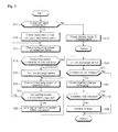
- Fig. 2 is a flowchart illustrating a method for power management and control, which is programmed in a ROM area of the control unit 56.
- the control unit 56 of the power management and control unit 50 in the system main body 20 reads data carried on the bus connection 12 in a predetermined period so as to determine whether the fuel cell pack 30 is connected to the system main body 20 (S10).
- step S10 If it is determined in step S10 that the fuel cell pack 30 is not connected to the system main body 20, the control unit 56 outputs a switching control signal SCTL to turn on the discharge switch 54 (S12). Accordingly, the voltage of the battery pack 51 is supplied as an operation voltage to the operation block 40 via the discharge switch 54, the consuming power sensor 53, and the DC-DC converter 52.
- the output voltage of the fuel cell pack 30 is supplied to the operation block 40 via the consuming power sensor 53 and the DC-DC converter 52.
- the operation block 40 consumes power while performing various operations according to a user's demand or task processing at a speed based on a preset internal system clock frequency.
- the consuming power sensor 53 connected between the power input terminal 10 and the operation block 40 senses the amount of a current consumed by the operation block 40 and supplies input terminals A1 and A2 of the control unit 56 with consuming power (CP) according to a load.
- CP consuming power
- the consuming power sensor 53 may be implemented in several different forms, it is implemented using a current sense resistor in the present invention.
- control unit 56 of the system main body 20 transmits and receives data to and from the fuel cell controller 36 of the fuel cell pack 30 via the bus connection 12 so as to recognize a connection state of the fuel cell pack 30.
- the control unit 56 also sequentially transmits and receives data to and from the fuel cell controller 36 of the fuel cell pack 30 and the secondary battery controller of the battery pack 51 via the bus connection 12 and the data bus 13, respectively, so as to check the electricity-generating capacity of the fuel cell pack 30 and the charged remaining capacity of the battery pack 51 (S14).
- the bus connection 12 and the data bus 13 are serial data buses that may be a system management (SM) bus or an inter integrated circuit (I 2 C) bus for clock and data transmission.
- SM system management
- I 2 C inter integrated circuit
- the control unit 56 converts an analog signal input via the input terminals A1 and A2 into a digital signal and checks the consuming power of the operation block 40 from the value of the digital signal (S16). After checking the voltage capacity of the fuel cell pack 30, the charged remaining capacity of the battery pack 51, and the consuming power of the operation block 40, the control unit 56 determines whether the output voltage of the fuel cell pack 30 is enough to drive the operation block 40 (S 18).
- control unit 56 compares the consuming power (CP) of the operation block 40 with the generated voltage capacity (FCVC) of the fuel cell pack 30 to determine whether the generated voltage capacity (FCVC) is greater than the consuming power (CP) of the operation block 40 (S18). If it is determined in step S 18 that the generated voltage capacity (FCVC) of the fuel cell pack 30 is greater than the consuming power (CP), the control unit 56 inactivates the switching control signal SCTL to turn off the discharge switch 54 (S20).
- control unit 56 analyzes the information on the charged remaining capacity of the battery pack 51, which has been acquired through data communication with the battery pack 51 via the data bus 13 in step S14, to determine whether charging the battery is required (S22). If it is determined in step S22 that the battery pack 51 is fully charged, the control unit 56 returns to the aforementioned initial step. If it is determined that the battery pack 51 is not fully charged, the control unit 56 activates the charging control signal CCS (S24).
- the charger 55 In response to the activated charging control signal CCS, the charger 55 converts the voltage of the fuel cell pack 30 input via the consuming power sensor 53 into a charging voltage (CV) with a preset level, thereby charging the battery pack 51.
- CV charging voltage
- control unit 56 communicates data with the secondary battery controller of the battery pack 51 via the data bus 13 to determine whether the secondary battery is fully charged (S26). If it is determined in step S26 that the secondary battery is not fully charged, the control unit 56 returns to the aforementioned initial step. If the battery pack 51 is fully charged, the control unit 56 inactivates the charging control signal CCS, thereby disabling the charger 55.
- the voltage of the fuel cell pack 30 is used to stably drive the operation block 40 and charge the battery pack 51.
- step S18 If it is determined in step S18 that the consuming power (CP) of the operation block 40 is greater than the generated voltage capacity (FCVC) of the fuel cell pack 30, the control unit 56 turns on the discharge switch 54 to establish a discharge path for the secondary battery in the battery pack 51 (S30) and then checks the consuming power of the operation block 40 sensed by the consuming power sensor 53 (S32).
- CP consuming power
- FCVC generated voltage capacity
- the charged voltage (BAT) of the battery pack 51 cooperates with the generated voltage (FCVC) output from the fuel cell pack 30, in the consuming power sensor 53. That is, the charged voltage (BAT) of the battery pack 51 is added to the generated voltage capacity (FCVC) of the fuel cell pack 30.
- control unit 56 After checking the consuming power (CP) of the operation block 40 in step S32, the control unit 56 determines whether the consuming power (CP) of the operation block 40 exceeds the sum of the generated voltage capacity (FCVC) of the fuel cell pack 30 and the voltage (BAT) of the battery pack 51 (S34).
- step S34 If it is determined in step S34 that the consuming power (CP) of the operation block 40 is less than the sum of the generated voltage capacity (FCVC) of the fuel cell pack 30 and the voltage (BAT) of the battery pack 51, the control unit 56 jumps to step S16 and then drives the operation block 40 with the both voltages.
- FCVC generated voltage capacity
- step S34 if it is determined in step S34 that the consuming power (CP) of the operation block 40 exceeds the sum of the generated voltage capacity (FCVC) of the fuel cell pack 30 and the voltage (BAT) of the battery pack 51, the control unit 56 provides the performance limit signal PLS to the BIOS 57 (S36).
- the BIOS 57 In response to the performance limit signal PLS, the BIOS 57 lowers the system clock frequency of the operation block 40 and limits the rotational speeds of the motors of the ODD, the FDD and the like to lower values. This process limits the performance of the operation block 40, thereby reducing the consuming power thereof.
- control unit 56 automatically lowers the system clock frequency of the operation block 40 or the rotational speeds of the motors consuming much power in such a manner that the consuming power of the system main body 20 does not exceed the generated voltage capacity of the fuel cell pack 30.
- the power management and control apparatus of the portable electronic equipment 1 establishes the discharge path for the battery pack 51 to supplement insufficient power using the charged voltage of the battery pack 51 if the consuming power of the system main body 20 exceeds the generated voltage capacity (FCVC) of the fuel cell pack 30. If the consuming power of the system main body 20 does not exceed the generated voltage capacity of the fuel cell pack 30 and the voltage of the battery pack 51 is not sufficiently charged, the power management and control apparatus enables the charger 55 so that the level of the charged voltage of the battery pack 51 is always in a fully charged state.
- FCVC generated voltage capacity
- the power management and control apparatus performs proper power management by limiting the performance of the operation block 40 to reduce overall power consumption in such a manner that the consuming power of the operation block 40 does not exceed the generated voltage capacity of the fuel cell pack 30.
- the portable electronic equipment is not limited only to a notebook computer but may be a variety of battery-powered electronic equipment such as PDAs, communication equipment, portable information terminals, and cameras.
- power management in portable electronic equipment powered by a voltage from a fuel cell pack is performed by monitoring the consuming power of an operation block in real time, charging/discharging a battery pack and limiting the performance of the operation block according to the sensed consuming power of the operation block and the generated voltage capacity of the fuel cell pack.
- the system is prevented from being shut down even when much power is temporarily consumed in the system main body.
Landscapes
- Engineering & Computer Science (AREA)
- Theoretical Computer Science (AREA)
- Power Engineering (AREA)
- Physics & Mathematics (AREA)
- General Engineering & Computer Science (AREA)
- General Physics & Mathematics (AREA)
- Fuel Cell (AREA)
- Charge And Discharge Circuits For Batteries Or The Like (AREA)
- Secondary Cells (AREA)
Applications Claiming Priority (2)
| Application Number | Priority Date | Filing Date | Title |
|---|---|---|---|
| KR1020060026658A KR101233504B1 (ko) | 2006-03-23 | 2006-03-23 | 연료전지와 축전지의 선택 제어방법 및 그 시스템 |
| KR1020070014948A KR101359091B1 (ko) | 2007-02-13 | 2007-02-13 | 휴대용 전자기기의 전원관리 제어장치 및 그 제어방법 |
Publications (2)
| Publication Number | Publication Date |
|---|---|
| EP1837735A2 true EP1837735A2 (fr) | 2007-09-26 |
| EP1837735A3 EP1837735A3 (fr) | 2012-05-09 |
Family
ID=38180161
Family Applications (1)
| Application Number | Title | Priority Date | Filing Date |
|---|---|---|---|
| EP20070104556 Withdrawn EP1837735A3 (fr) | 2006-03-23 | 2007-03-21 | Gestion et contrôle de l'alimentation dans un équipement électronique |
Country Status (2)
| Country | Link |
|---|---|
| US (1) | US7863775B2 (fr) |
| EP (1) | EP1837735A3 (fr) |
Cited By (6)
| Publication number | Priority date | Publication date | Assignee | Title |
|---|---|---|---|---|
| CN102538884A (zh) * | 2011-12-21 | 2012-07-04 | 王维 | 一种自记式超声波明渠流量计量装置 |
| WO2014200712A3 (fr) * | 2013-06-13 | 2015-03-05 | Microsoft Corporation | Traitement intégré sur puce et génération d'énergie |
| US9892029B2 (en) | 2015-09-29 | 2018-02-13 | International Business Machines Corporation | Apparatus and method for expanding the scope of systems management applications by runtime independence |
| US9939873B1 (en) | 2015-12-09 | 2018-04-10 | International Business Machines Corporation | Reconfigurable backup and caching devices |
| US9996397B1 (en) | 2015-12-09 | 2018-06-12 | International Business Machines Corporation | Flexible device function aggregation |
| US10170908B1 (en) | 2015-12-09 | 2019-01-01 | International Business Machines Corporation | Portable device control and management |
Families Citing this family (37)
| Publication number | Priority date | Publication date | Assignee | Title |
|---|---|---|---|---|
| KR20090009651A (ko) * | 2007-07-20 | 2009-01-23 | 삼성에스디아이 주식회사 | 포트를 통한 양방향 전력 전달이 가능한 전자기기 및 그동작 방법 |
| US7834612B2 (en) * | 2007-07-26 | 2010-11-16 | Altronix Corporation | Method and apparatus for regulating voltage in a remote device |
| TW201006091A (en) * | 2008-07-18 | 2010-02-01 | Nan Ya Printed Circuit Board | Battery management systems and methods |
| WO2010027422A2 (fr) * | 2008-08-25 | 2010-03-11 | Eveready Battery Company, Inc. | Alimentation de batterie pourvue d'une batterie consommant un fluide, dotee d'un gestionnaire de fluide ameliore |
| WO2010057115A2 (fr) | 2008-11-17 | 2010-05-20 | Express Imaging Systems, Llc | Commande électronique pour réguler la puissance pour un éclairage à semi-conducteurs et procédés de commande |
| US8283893B2 (en) * | 2009-02-05 | 2012-10-09 | Samsung Sdi Co., Ltd. | Protection circuit for battery pack and battery pack including the same |
| JP5480520B2 (ja) * | 2009-03-27 | 2014-04-23 | 伊藤忠商事株式会社 | 電池制御装置、車両、及び電池制御方法 |
| WO2010135575A2 (fr) | 2009-05-20 | 2010-11-25 | Express Imaging Systems, Llc | Détection de mouvement à grande portée pour la commande de l'éclairage |
| JP2011125122A (ja) * | 2009-12-09 | 2011-06-23 | Sony Corp | バッテリ制御システム、バッテリ制御装置、バッテリ制御方法およびプログラム |
| JP5552817B2 (ja) * | 2010-01-25 | 2014-07-16 | ソニー株式会社 | 電力管理システム、電力管理装置、電力管理方法、蓄電装置、及び電動移動体 |
| CN102455968A (zh) * | 2010-10-25 | 2012-05-16 | 纬创资通股份有限公司 | 电源管理方法及便携式电子装置 |
| US8901825B2 (en) | 2011-04-12 | 2014-12-02 | Express Imaging Systems, Llc | Apparatus and method of energy efficient illumination using received signals |
| US9360198B2 (en) | 2011-12-06 | 2016-06-07 | Express Imaging Systems, Llc | Adjustable output solid-state lighting device |
| US9497393B2 (en) | 2012-03-02 | 2016-11-15 | Express Imaging Systems, Llc | Systems and methods that employ object recognition |
| US9131552B2 (en) | 2012-07-25 | 2015-09-08 | Express Imaging Systems, Llc | Apparatus and method of operating a luminaire |
| US8896215B2 (en) | 2012-09-05 | 2014-11-25 | Express Imaging Systems, Llc | Apparatus and method for schedule based operation of a luminaire |
| US9301365B2 (en) * | 2012-11-07 | 2016-03-29 | Express Imaging Systems, Llc | Luminaire with switch-mode converter power monitoring |
| US9288873B2 (en) | 2013-02-13 | 2016-03-15 | Express Imaging Systems, Llc | Systems, methods, and apparatuses for using a high current switching device as a logic level sensor |
| TWM458020U (zh) * | 2013-02-19 | 2013-07-21 | Delta Electronics Inc | 電池備援系統及其電池備用模組 |
| US9466443B2 (en) | 2013-07-24 | 2016-10-11 | Express Imaging Systems, Llc | Photocontrol for luminaire consumes very low power |
| US9414449B2 (en) | 2013-11-18 | 2016-08-09 | Express Imaging Systems, Llc | High efficiency power controller for luminaire |
| US9462662B1 (en) | 2015-03-24 | 2016-10-04 | Express Imaging Systems, Llc | Low power photocontrol for luminaire |
| US10228740B2 (en) * | 2015-06-24 | 2019-03-12 | Intel Corporation | Sensor device and method |
| US9538612B1 (en) | 2015-09-03 | 2017-01-03 | Express Imaging Systems, Llc | Low power photocontrol for luminaire |
| KR102657052B1 (ko) | 2016-04-12 | 2024-04-15 | 삼성전자주식회사 | 배터리 충전 방법 및 전자 장치 |
| US9924582B2 (en) | 2016-04-26 | 2018-03-20 | Express Imaging Systems, Llc | Luminaire dimming module uses 3 contact NEMA photocontrol socket |
| US9985429B2 (en) | 2016-09-21 | 2018-05-29 | Express Imaging Systems, Llc | Inrush current limiter circuit |
| US10230296B2 (en) | 2016-09-21 | 2019-03-12 | Express Imaging Systems, Llc | Output ripple reduction for power converters |
| US10904992B2 (en) | 2017-04-03 | 2021-01-26 | Express Imaging Systems, Llc | Systems and methods for outdoor luminaire wireless control |
| US11375599B2 (en) | 2017-04-03 | 2022-06-28 | Express Imaging Systems, Llc | Systems and methods for outdoor luminaire wireless control |
| CN107933363B (zh) * | 2017-12-10 | 2019-03-22 | 东营思科维新能源科技有限公司 | 使用计算机管理电动车电池的系统 |
| CN110001421A (zh) * | 2018-10-18 | 2019-07-12 | 丰疆智慧农业股份有限公司 | 混合动力拖拉机及其充电方法 |
| US11317497B2 (en) | 2019-06-20 | 2022-04-26 | Express Imaging Systems, Llc | Photocontroller and/or lamp with photocontrols to control operation of lamp |
| US11212887B2 (en) | 2019-11-04 | 2021-12-28 | Express Imaging Systems, Llc | Light having selectively adjustable sets of solid state light sources, circuit and method of operation thereof, to provide variable output characteristics |
| CN112994124B (zh) * | 2019-12-12 | 2024-07-19 | 中国科学院大连化学物理研究所 | 一种水下组合能源供电方法及系统 |
| JP7366275B2 (ja) * | 2020-08-21 | 2023-10-20 | 三菱電機株式会社 | 燃料電池システムおよび燃料電池システムの制御方法 |
| US12439488B2 (en) | 2022-12-09 | 2025-10-07 | Express Imaging Systems, Llc | Field adjustable output for dimmable luminaires |
Citations (1)
| Publication number | Priority date | Publication date | Assignee | Title |
|---|---|---|---|---|
| US20030110012A1 (en) * | 2001-12-06 | 2003-06-12 | Doron Orenstien | Distribution of processing activity across processing hardware based on power consumption considerations |
Family Cites Families (6)
| Publication number | Priority date | Publication date | Assignee | Title |
|---|---|---|---|---|
| US6498460B1 (en) * | 2001-12-14 | 2002-12-24 | Compaq Information Technologies Group, L.P. | Prioritization-based power management protocol in a computer system |
| JP3715608B2 (ja) * | 2002-09-30 | 2005-11-09 | 株式会社東芝 | 電子機器システムおよび電池ユニット |
| JP2005032039A (ja) * | 2003-07-07 | 2005-02-03 | Sony Corp | 電子機器及び電子機器の電源管理制御方法、並びに電源装置 |
| US20050086545A1 (en) * | 2003-10-17 | 2005-04-21 | Dell Products L.P. | Information handling system including fast acting current monitoring and throttling capability |
| US7446501B2 (en) * | 2004-03-19 | 2008-11-04 | More Energy Ltd. | Integrated fuel cell controller for devices |
| WO2008092056A1 (fr) * | 2007-01-25 | 2008-07-31 | Eveready Battery Company, Inc. | Système d'alimentation portable |
-
2007
- 2007-03-21 EP EP20070104556 patent/EP1837735A3/fr not_active Withdrawn
- 2007-03-22 US US11/689,600 patent/US7863775B2/en not_active Expired - Fee Related
Patent Citations (1)
| Publication number | Priority date | Publication date | Assignee | Title |
|---|---|---|---|---|
| US20030110012A1 (en) * | 2001-12-06 | 2003-06-12 | Doron Orenstien | Distribution of processing activity across processing hardware based on power consumption considerations |
Cited By (8)
| Publication number | Priority date | Publication date | Assignee | Title |
|---|---|---|---|---|
| CN102538884A (zh) * | 2011-12-21 | 2012-07-04 | 王维 | 一种自记式超声波明渠流量计量装置 |
| WO2014200712A3 (fr) * | 2013-06-13 | 2015-03-05 | Microsoft Corporation | Traitement intégré sur puce et génération d'énergie |
| KR20160019447A (ko) * | 2013-06-13 | 2016-02-19 | 마이크로소프트 테크놀로지 라이센싱, 엘엘씨 | 온-칩 통합 처리 및 전력 발생 기법 |
| CN105359333A (zh) * | 2013-06-13 | 2016-02-24 | 微软技术许可有限责任公司 | 片上集成处理和发电 |
| US9892029B2 (en) | 2015-09-29 | 2018-02-13 | International Business Machines Corporation | Apparatus and method for expanding the scope of systems management applications by runtime independence |
| US9939873B1 (en) | 2015-12-09 | 2018-04-10 | International Business Machines Corporation | Reconfigurable backup and caching devices |
| US9996397B1 (en) | 2015-12-09 | 2018-06-12 | International Business Machines Corporation | Flexible device function aggregation |
| US10170908B1 (en) | 2015-12-09 | 2019-01-01 | International Business Machines Corporation | Portable device control and management |
Also Published As
| Publication number | Publication date |
|---|---|
| US7863775B2 (en) | 2011-01-04 |
| EP1837735A3 (fr) | 2012-05-09 |
| US20070224461A1 (en) | 2007-09-27 |
Similar Documents
| Publication | Publication Date | Title |
|---|---|---|
| US7863775B2 (en) | Power management and control in electronic equipment | |
| CN103777730B (zh) | 电源管理电路及其方法 | |
| US20110057605A1 (en) | Power Supply System with Power Saving Function and Power Supply Method Thereof | |
| CN114448010A (zh) | 一种充放电的控制系统、方法及电池包 | |
| US6977482B2 (en) | Selector circuit for power management in multiple battery systems | |
| US9407104B2 (en) | Battery powered charger | |
| EP1225674B1 (fr) | Appareil électronique portable, dispositif de charge et procédé correspondant | |
| JP4197189B2 (ja) | 電力供給のための回路および動作方法 | |
| US7183748B1 (en) | Electric charger and power supply device for portable terminal | |
| US7436149B2 (en) | Systems and methods for interfacing a battery-powered information handling system with a battery pack of a physically separable battery-powered input or input/output device | |
| JP4783454B2 (ja) | 電源供給装置、システムおよび充放電制御方法 | |
| EP1837734A2 (fr) | Appareil et procédé de gestion d'énergie de blocs-batteries dans un appareil portable | |
| US20080203817A1 (en) | Power architecture for battery powered remote devices | |
| US8862907B2 (en) | Information processing apparatus and power supply control method | |
| US20090322287A1 (en) | Charging system | |
| JP2007215251A (ja) | 蓄電池の充電システムおよび充電方法 | |
| JP2009033879A (ja) | 充電システムおよび充電方法 | |
| CN101043146B (zh) | 用于管理便携式设备中的电池组件的电能的装置和方法 | |
| US20050068002A1 (en) | Cell unit and power supply control method | |
| CN1237478C (zh) | 个人计算机卡电源管理系统 | |
| CN100507805C (zh) | 电子设备中的功率管理与控制 | |
| TW201011513A (en) | Multi-output voltage battery module and electronic device using the same | |
| US20050048330A1 (en) | Electronic system and power supply method | |
| US20070275271A1 (en) | Method and apparatus for controlling fuel cell in portable device | |
| JP4806927B2 (ja) | 電源装置 |
Legal Events
| Date | Code | Title | Description |
|---|---|---|---|
| PUAI | Public reference made under article 153(3) epc to a published international application that has entered the european phase |
Free format text: ORIGINAL CODE: 0009012 |
|
| 17P | Request for examination filed |
Effective date: 20070419 |
|
| AK | Designated contracting states |
Kind code of ref document: A2 Designated state(s): AT BE BG CH CY CZ DE DK EE ES FI FR GB GR HU IE IS IT LI LT LU LV MC MT NL PL PT RO SE SI SK TR |
|
| AX | Request for extension of the european patent |
Extension state: AL BA HR MK YU |
|
| PUAL | Search report despatched |
Free format text: ORIGINAL CODE: 0009013 |
|
| AK | Designated contracting states |
Kind code of ref document: A3 Designated state(s): AT BE BG CH CY CZ DE DK EE ES FI FR GB GR HU IE IS IT LI LT LU LV MC MT NL PL PT RO SE SI SK TR |
|
| AX | Request for extension of the european patent |
Extension state: AL BA HR MK RS |
|
| RIC1 | Information provided on ipc code assigned before grant |
Ipc: G06F 1/26 20060101AFI20120330BHEP |
|
| AKX | Designation fees paid |
Designated state(s): DE ES FR GB NL |
|
| 17Q | First examination report despatched |
Effective date: 20160801 |
|
| STAA | Information on the status of an ep patent application or granted ep patent |
Free format text: STATUS: THE APPLICATION IS DEEMED TO BE WITHDRAWN |
|
| 18D | Application deemed to be withdrawn |
Effective date: 20170214 |