EP1837737A2 - Dispositif d'entrée rotatif - Google Patents
Dispositif d'entrée rotatif Download PDFInfo
- Publication number
- EP1837737A2 EP1837737A2 EP06255464A EP06255464A EP1837737A2 EP 1837737 A2 EP1837737 A2 EP 1837737A2 EP 06255464 A EP06255464 A EP 06255464A EP 06255464 A EP06255464 A EP 06255464A EP 1837737 A2 EP1837737 A2 EP 1837737A2
- Authority
- EP
- European Patent Office
- Prior art keywords
- magnet
- input apparatus
- wheel
- rotary input
- circuit board
- Prior art date
- Legal status (The legal status is an assumption and is not a legal conclusion. Google has not performed a legal analysis and makes no representation as to the accuracy of the status listed.)
- Withdrawn
Links
Images


Classifications
-
- H—ELECTRICITY
- H01—ELECTRIC ELEMENTS
- H01H—ELECTRIC SWITCHES; RELAYS; SELECTORS; EMERGENCY PROTECTIVE DEVICES
- H01H25/00—Switches with compound movement of handle or other operating part
- H01H25/04—Operating part movable angularly in more than one plane, e.g. joystick
- H01H25/041—Operating part movable angularly in more than one plane, e.g. joystick having a generally flat operating member depressible at different locations to operate different controls
-
- G—PHYSICS
- G06—COMPUTING OR CALCULATING; COUNTING
- G06F—ELECTRIC DIGITAL DATA PROCESSING
- G06F3/00—Input arrangements for transferring data to be processed into a form capable of being handled by the computer; Output arrangements for transferring data from processing unit to output unit, e.g. interface arrangements
- G06F3/01—Input arrangements or combined input and output arrangements for interaction between user and computer
- G06F3/016—Input arrangements with force or tactile feedback as computer generated output to the user
-
- G—PHYSICS
- G06—COMPUTING OR CALCULATING; COUNTING
- G06F—ELECTRIC DIGITAL DATA PROCESSING
- G06F3/00—Input arrangements for transferring data to be processed into a form capable of being handled by the computer; Output arrangements for transferring data from processing unit to output unit, e.g. interface arrangements
- G06F3/01—Input arrangements or combined input and output arrangements for interaction between user and computer
- G06F3/03—Arrangements for converting the position or the displacement of a member into a coded form
- G06F3/033—Pointing devices displaced or positioned by the user, e.g. mice, trackballs, pens or joysticks; Accessories therefor
- G06F3/0362—Pointing devices displaced or positioned by the user, e.g. mice, trackballs, pens or joysticks; Accessories therefor with detection of one-dimensional [1D] translations or rotations of an operating part of the device, e.g. scroll wheels, sliders, knobs, rollers or belts
-
- H—ELECTRICITY
- H01—ELECTRIC ELEMENTS
- H01H—ELECTRIC SWITCHES; RELAYS; SELECTORS; EMERGENCY PROTECTIVE DEVICES
- H01H3/00—Mechanisms for operating contacts
- H01H3/32—Driving mechanisms, i.e. for transmitting driving force to the contacts
- H01H3/50—Driving mechanisms, i.e. for transmitting driving force to the contacts with indexing or locating means, e.g. indexing by ball and spring
- H01H2003/506—Driving mechanisms, i.e. for transmitting driving force to the contacts with indexing or locating means, e.g. indexing by ball and spring making use of permanent magnets
-
- H—ELECTRICITY
- H01—ELECTRIC ELEMENTS
- H01H—ELECTRIC SWITCHES; RELAYS; SELECTORS; EMERGENCY PROTECTIVE DEVICES
- H01H25/00—Switches with compound movement of handle or other operating part
- H01H25/04—Operating part movable angularly in more than one plane, e.g. joystick
- H01H25/041—Operating part movable angularly in more than one plane, e.g. joystick having a generally flat operating member depressible at different locations to operate different controls
- H01H2025/043—Operating part movable angularly in more than one plane, e.g. joystick having a generally flat operating member depressible at different locations to operate different controls the operating member being rotatable around wobbling axis for additional switching functions
-
- H—ELECTRICITY
- H01—ELECTRIC ELEMENTS
- H01H—ELECTRIC SWITCHES; RELAYS; SELECTORS; EMERGENCY PROTECTIVE DEVICES
- H01H25/00—Switches with compound movement of handle or other operating part
- H01H25/04—Operating part movable angularly in more than one plane, e.g. joystick
- H01H2025/048—Operating part movable angularly in more than one plane, e.g. joystick having a separate central push, slide or tumbler button which is not integral with the operating part that surrounds it
Definitions
- the present invention relates to a rotary input apparatus.
- a mobile terminal has the numbers 0-9 and the symbols * and # on a keypad of 12 keys.
- numbers there are also alphabet letters as well as consonants and vowels of Korean (or other) letters marked on such a keypad, to enable the input of information including numbers and letters.
- navigation keys formed above the keypad equipped with a variety of functions such as phone number search, writing and managing text messages, and connecting to the Internet, etc.
- navigation keys such as button types and rotary types, etc., but the use of rotary input apparatus is currently increasing, as they enable various functions such as menu browsing, etc.
- Rotary input apparatus are used in televisions, camcorders, and PDA's (personal digital assistants), etc., as input apparatus in the form of rotary switches, rotary encoders, and rotary volume dials, etc.
- An example of a conventional rotary input apparatus that generates click sensations include, first, a rotary input apparatus for generating click sensations consisting of a rotary member having a plurality of concavo-convex portions, a click member for engagement with and disengagement from the concavo-convex portions, a biasing member for urging the click member elastically in a direction towards the concavo-convex portions, and a holding member for holding the biasing member.
- a second example includes a rotary input apparatus consisting of a rotor capable of free rotational motion, cam seats provided in the rotor and having concavo-convex portions, clicking members to be put in slide contact with the cam seats, and a holding member to hold the clicking members, where the holding member is furnished with a plurality of holding parts for holding the clicking members.
- a rotary input apparatus consisting of a rotor capable of free rotational motion, cam seats provided in the rotor and having concavo-convex portions, clicking members to be put in slide contact with the cam seats, and a holding member to hold the clicking members, where the holding member is furnished with a plurality of holding parts for holding the clicking members.
- Such conventional rotary input apparatus for generating click sensations have grooves such as the concavo-convex portions or the cam seats, where click sensations are created when click members are caught on and disengaged from these grooves.
- the fact that click sensations are created even when they are not desired by the user presents an inconvenience in usage.
- click sensations are created as the click members are caught on and disengaged from concavo-convex portions or cam seats of constant sizes, the magnitude of the click sensations cannot be regulated.
- the present invention aims to provide a rotary input apparatus with which the user can decide whether or not to create click sensations and can regulate the magnitude of the click sensations.
- the invention also aims to provide a rotary input apparatus having a simple composition and excellent durability.
- a rotary input apparatus comprising a rotatable wheel, a first magnet joined to a side of the wheel for cooperation with the wheel and magnetized to have alternating N- and S-poles, a detection element positioned to face the first magnet for detecting changes in magnetism of the first magnet, a second magnet positioned to face the first magnet and magnetized to have alternating N- and S-poles in correspondence with the first magnet, a printed circuit board on which are mounted the detection element and the second magnet, a base to which the printed circuit board is secured, and a holder joined to the base and interposed between the wheel and the base to rotatably support the wheel.
- the second magnet may preferably be an electromagnet operated by receiving an electrical current from a circuit formed on the printed circuit board, and on the printed circuit board may be formed a circuit for regulating the amount of the electrical current delivered to the second magnet, or a circuit for modifying the direction of the electrical current delivered to the second magnet.
- the first magnet may be joined in a circumferential shape along the perimeter portion of a side of the wheel, and multiple second magnets may be mounted on the printed circuit board in correspondence with the first magnet. It may be preferable for the plurality of second magnets to be arranged in constant intervals.
- the number of N-poles or the number of S-poles on the first magnet may be an integer multiple of the number of second magnets.
- the second magnet may be positioned to face an N-pole or an S-pole of the first magnet.
- Some of the plurality of second magnets may be positioned to face N- or S-poles of the first magnet, and some of the plurality of second magnets may be positioned to face the boundaries between N- and S-poles of the first magnet.
- the holder may comprise a body portion positioned in contact with the wheel, an inclination portion extending in a predetermined angle from the body portion, and a securing portion extending from the inclination portion and joined to the base.
- the inclination portion may comprise a support hole for holding at least a portion of the detection element or the second magnet.
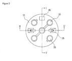
- a rotary input apparatus comprises a rotatably joined wheel 11, a washer 25 which secures the wheel 11 to a holder, a center key 29 joined at the center of the wheel 11, a ring-shaped magnet 13 secured to the bottom of the wheel 11 which rotates together with the wheel 11, the holder 15 joined to the upper surface of a base 39 which rotatably supports the wheel 11, a printed circuit board 31 secured to the upper surface of the base 39, Hall sensors 35 positioned in grooves of the printed circuit board 31 which are detection elements for sensing the rotation of the magnet 13, and an electromagnet 45 having an N- or S-pole mounted on the printed circuit board 31.
- a certain click sensation is created due to the interaction between the rotary magnet 13 and the electromagnet 45 when the wheel 11 is rotated, to provide a better tactile feel.
- the user can determine whether or not a click sensation is to be created and can regulate its magnitude, by allowing or disallowing electrical flow delivered to the electromagnet and by controlling the magnitude of the electrical flow.
- the rotary input apparatus according to this embodiment is a structure for generating click sensations, and as it is equipped with an electromagnet mounted on the printed circuit board, it is characterized by both a simple composition and excellent durability.
- the wheel 11 is generally shaped as a circular plate, with an insertion hole 14 formed in the center through which the center key 29 may be inserted.
- the wheel 11 has a plurality of securing protrusions 12 adjacent to the insertion hole 14 that protrude downwards.
- the wheel 11 is rotatably secured to the holder 15.
- the magnet 13 On the bottom surface of the wheel 11 is secured the magnet 13, which is magnetized to have multiple poles.
- the wheel 11 is rotated together with the magnet 13 by user operation, whereby a variety of inputs are made as the Hall sensors 35 sense the rotation angle, direction, and speed, etc., of the magnet 13.
- the securing protrusions 12, as illustrated in Fig. 3 or 4, are inserted through the center hole 21 of the holder 15 and the rotation holes 27 of the washer 25, with the ends processed such that they are not detached from the rotation holes 27.
- the washer 25 is inserted and secured onto the center of the holder 15, whereby the wheel 11 is secured to the holder 15.
- the central angles of the rotation holes 27 of the washer 25, through which the securing protrusions 12 are inserted, define the angle by which the wheel 11 is able to rotate.
- the magnet 13 is attached to the bottom surface of the wheel 11 to be rotated together with the wheel 11, and such rotation of the magnet 13 is sensed by the Hall sensors 35 for an input based on the rotation angle.
- an attraction is generated by the electromagnet 45 having an N- or S-pole, whereby a click sensation is generated.
- the magnet 13 has the shape of a ring magnetized to have a plurality of alternating N- and S-poles, and the Hall sensors 35 are able to detect the rotation angle, direction, and speed of the wheel 11 according to the changes in N- and S-poles above the Hall sensors 35.
- the holder 15 is secured to one side of the base 39 and rotatably supports the wheel 11.
- the holder 15 may be made of metal, such as stainless steel, etc., so that when the particular force applied on the wheel 11 is removed, the wheel 11 is returned to its original position due to the elasticity of the holder 15 itself.
- the holder 15 may be formed by press processing, etc. Of course, the holder 15 may also be formed by plastics, etc., that are high in elasticity.
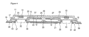
- the holder 15 includes a ring-shaped body portion 18, and a support portion 16 protruding from the perimeter of the body portion 18 and secured to a side of the base 39.
- the body portion 18 has a center hole 21 in the middle, and the support portion 16 protruding in four directions around the center hole 21 comprises an inclination portion 17 protruding downwards in a particular inclination, and a securing portion 19 extending horizontally from the end of the inclination portion 17.
- the inclination portion 17 protrudes outwards and connects the body portion 18 and the securing portion 19. Since the inclination portion 17 is formed by metal, etc., having elasticity, when an external force applied on the holder 15 is removed, the holder 15 is returned to its original position by means of the elasticity of the inclination portion 17. Thus, even when a particular portion of the wheel 11 is pressed so that the wheel 11 becomes tilted, this elasticity allows it to be restored to its original position.
- the securing portion 19 extends from the end of the inclination portion 17 and is secured to the upper surface of the base 39 to secure the holder 15. The securing portion 19 may be secured to the base 39 by means of adhesive or tape, etc.
- the rotary input apparatus Since the holder 15 is secured directly to a side of the base 39 by means of adhesive, etc., the rotary input apparatus according to this embodiment has superior endurance to external impact. Also, the elasticity of the holder 15, which is formed of metal, allows not only the holder 15 itself but also the wheel 11 to be restored to their original positions, to provide a better tactile feel.
- support portion holes 20 In the support portion 16 are formed support portion holes 20. As illustrated in Fig. 3 or 4, portions of the Hall sensors 35 and the electromagnet 45 may be positioned in the support portion holes 20. Also, the body portion 18 has ledges 23 formed adjacent to the center hole 21.
- the support portion holes 20 in the support portion 16 are formed to correspond with the Hall sensors 35 and electromagnet 45 mounted on the printed circuit board 31, and as illustrated in Fig. 3 or 4, hold portions of the Hall sensors 35 and electromagnet 45.
- the center hole 21 is formed in the center of the holder 15. Also, the wheel 11 is rotatably inserted onto a perimeter 22 forming the center hole 21, to prevent the wheel 11 from becoming detached.
- the ledges 23, as illustrated in Fig. 2, are formed adjacent to the center hole 21. The washer 25 is inserted and secured onto the ledges 23.
- the washer 25 is generally shaped as a donut, with a plurality of rotation holes 27 formed in certain intervals along the ring.
- the washer 25 is inserted and secured onto the ledges 23 to define the angle by which the wheel 11 is able to rotate. While there are four arc-shaped rotation holes 27 illustrated in this embodiment, the invention is not thus limited, and it is to be appreciated that the number and central angles of the rotation holes 27 may be changed according to design considerations. For example, one or two rotation holes 27 formed along the ring of the washer 25 with a central angle of 180° or 360° may be used for the rotation holes 27.
- the center key 29 is inserted through the insertion hole 14 of the wheel 11.
- the center key 29 is pressed by the user to perform a particular function, examples of which include connecting to the Internet or receiving DMB (Digital Multimedia Broadcasting), etc.
- DMB Digital Multimedia Broadcasting
- the printed circuit board 31 has the shape of a circular plate in correspondence with the base 39, with a plurality of dome buttons 33 formed on one side in correspondence with the push protrusions formed on the reverse side of the holder 15, and with the Hall sensors 35 and electromagnet 45 mounted facing the magnet 13. Also, there are receiving holes 37 formed on the printed circuit board 31 in which at least portions of the Hall sensors 35 may be inserted.
- the printed circuit board 31 is formed with a diameter somewhat shorter than the diameter of the base 39, in order to allow a sufficient area where the securing portion 19 of the holder 15 may be secured.
- the printed circuit board 31 supplies an electrical current having a certain magnitude and direction to the electromagnet 45, and this electrical current allows the electromagnet 45 to have an N- or S-pole. Since the printed circuit board 31 is able to block the electrical current inputted to the electromagnet 45, the user may change the settings so that click sensations are not generated during the rotation of the wheel 11. Also, the printed circuit board 31 can regulate the magnitude of the electrical current delivered to the electromagnet 45, thereby regulating the magnitude of the click sensations.
- the dome buttons 33 are pressed by push protrusions (not shown) formed on the reverse side of the holder 15 to perform separate functions. While in this embodiment the dome buttons 33 are illustrated as being pressed by means of the wheel 11, the invention is not thus limited, and any composition may be used in which certain pressing performs separate functions. For example, pressure sensors or contact sensors may also be used instead of the dome buttons 33.
- the receiving holes 37 are formed on the printed circuit board 31 in correspondence with the support portion holes 20 of the holder 15, and as illustrated in Figs. 3 and 4, at least portions of the Hall sensors 35 are positioned in the receiving holes 37.
- the thickness of the input device in the present embodiment may be reduced by the by the thickness of a receiving hole 37.
- the detection element may be a Hall sensor (Hall effect sensor), which is a silicon semiconductor using the effect of electromotive forces being generated when electrons experience the Lorentz force in a magnetic field and their direction is curved.
- the Hall sensors generate electromotive forces that are proportional to the rotation of the magnet 13 attached to the wheel 11, which are transferred via the printed circuit board 31 to an outside control unit (not shown).
- the detection element is not limited to Hall sensors, and any element may be used which can detect the rotation of the magnet 13.
- MR magnetic-resistive
- GMR giant magneto-resistive
- An MR sensor or a GMR sensor is an element of which the resistance value is changed according to changes in the magnetic field, and utilizes the property that electromagnetic forces curve and elongate the carrier path in a solid to change the resistance.
- MR sensors or GMR sensors small in size with high signal levels, but also they have excellent sensitivity to allow operation in low-level magnetic fields, and they are also superior in terms of temperature stability.
- the Hall sensors 35 are secured to the printed circuit board 31 by leads 36, where the leads 36 are inserted through the insertion holes 43 of the base 39 and secured to the reverse side of the printed circuit board 31.
- the base 39 as illustrated in Fig. 1, has the shape of a circular plate, and rotatably supports the holder 15 and the wheel 11.
- the diameter of the base 39 is formed to be somewhat longer than that of the printed circuit board 31.
- insertion holes 43 are formed on the base 39 in correspondence with the receiving holes 37 of the printed circuit board 31. As illustrated in Fig. 3, portions of the Hall sensors 35 are positioned in the insertion holes 43, whereby the thickness of the rotary input apparatus may further be reduced by the thickness of the insertion holes 43.
- the electromagnet 45 is mounted on the printed circuit board 31 and generates an N- or S-pole by means of the electrical current inputted via the printed circuit board 31.
- the polarity of the electromagnet 45 thus generated creates certain click sensations by interacting with the
- N- or S-poles of the magnet 13 are controlled by the printed circuit board 31.
- FIG. 5 there are six pairs of alternating N- and S-poles on the magnet 13 according to an embodiment of the invention, and there is one electromagnet 45 on the printed circuit board 31 facing an N- or S-pole of the magnet 13.
- the electromagnet 45 has an S-pole, there is attraction between the magnet 13 and the electromagnet 45. Due to this attraction between the magnet 13 and the electromagnet 45, a click sensation is generated when the magnet is rotated. Under this circumstance, the user applies a torque sufficient to overcome this attraction, and in the process of overcoming the attraction between the magnet 13 and the electromagnet 45, the user is made to feel a click sensation.
- the electromagnet 45 When the electromagnet 45 is made to face an S-pole of the magnet 13 due to the rotation of the magnet 13, the repulsion generated and the attraction to the surrounding N-poles allow easier rotation in the clockwise or counterclockwise direction. Since, in the embodiment illustrated in Fig. 5, the N- and S-poles are arranged in 30° angles and the minimum angle between an N-pole (or S-pole) and another N-pole (or S-pole) is 60°, six click sensations are created during 1 rotation of the wheel 11.
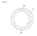
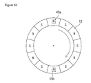
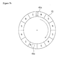
- electromagnet Although one electromagnet is illustrated in Fig. 5, the invention is not thus limited, and as illustrated in Figs. 6a and 6b, two or more electromagnets may be used.
- one electromagnet 45a is positioned facing an N-pole of the magnet 13, while the other electromagnet 45b is positioned on the boundary between an N- and S-pole.
- the first electromagnet 45a and the second electromagnet 45b each have an S-pole.
- the second electromagnet 45b is positioned at the boundary between an N- and S-pole, where there is an attraction of the second electromagnet 45b to the N-pole and a repulsion to the S-pole, so that a torque is provided that tends toward rotating the magnet 13 in the clockwise direction. As this torque is small compared to the attraction between the first electromagnet 45a and the N-pole, the magnet 13 is kept still and is not rotated.
- the user When the user wishes to apply a certain torque on the wheel 11 to rotate the magnet 13 clockwise, the user provides a torque of a strength sufficient to overcome the attraction between the first electromagnet 45a and the N-pole of the magnet 13, in the process of which the second electromagnet 45b positioned at the boundary between an N- and S-pole allows the magnet 13 to be rotated more easily.
- the rotation of the magnet 13 causes the first electromagnet 45a to be positioned at the boundary between an N- and S-pole, and causes the second electromagnet 45b to be positioned facing an N-pole.
- an attraction is generated between the second electromagnet 45b and the N-pole of the magnet 13, while the first electromagnet 45a is positioned at the boundary between the N- and S-pole to provide a force that tends toward rotating the magnet 13 clockwise. Therefore, according to the embodiment illustrated in Figs. 7a and 7b, a click sensation is generated every time the magnet 13 is rotated 15°.
- the wheel 11 When a rotational force is applied by a user on an outer side of the center key 29, the wheel 11 is rotated while inserted onto the perimeter 22 of the holder 15, which causes the magnet 13 to rotate together with the wheel 11.
- the Hall sensors 35 can sense the changes in poles due to the rotation of the magnet 13, to recognize the rotation direction, speed, and angle of the wheel 11.
- the Hall sensors 35 generate output signals corresponding to the rotation direction, rotation angle, and rotation speed of the wheel 11, which are transmitted via the printed circuit board 31 to an outside control unit, and the control unit identifies the output signals to perform an input corresponding to the rotation of the wheel 11.
- each of the dome buttons 33 positioned on the printed circuit board 31 to perform its own function.
- each dome button 33 may function as a hot key for launching a text message function, searching phone numbers, connecting to the Internet, or receiving satellite broadcasts, etc.
- center key 29 may also perform a separate function when pressed by a user.
- a rotary input apparatus is provided with which the user can decide whether or not to create click sensations and can regulate the magnitude of the click sensations, where the rotary input apparatus has a simple composition and yet has excellent durability.
Landscapes
- Engineering & Computer Science (AREA)
- General Engineering & Computer Science (AREA)
- Theoretical Computer Science (AREA)
- Human Computer Interaction (AREA)
- Physics & Mathematics (AREA)
- General Physics & Mathematics (AREA)
- Switches With Compound Operations (AREA)
- Input From Keyboards Or The Like (AREA)
- Rotary Switch, Piano Key Switch, And Lever Switch (AREA)
Applications Claiming Priority (1)
| Application Number | Priority Date | Filing Date | Title |
|---|---|---|---|
| KR20060026018 | 2006-03-22 |
Publications (1)
| Publication Number | Publication Date |
|---|---|
| EP1837737A2 true EP1837737A2 (fr) | 2007-09-26 |
Family
ID=38068439
Family Applications (1)
| Application Number | Title | Priority Date | Filing Date |
|---|---|---|---|
| EP06255464A Withdrawn EP1837737A2 (fr) | 2006-03-22 | 2006-10-24 | Dispositif d'entrée rotatif |
Country Status (2)
| Country | Link |
|---|---|
| US (1) | US7417422B2 (fr) |
| EP (1) | EP1837737A2 (fr) |
Cited By (1)
| Publication number | Priority date | Publication date | Assignee | Title |
|---|---|---|---|---|
| EP3198717A4 (fr) * | 2014-09-22 | 2018-04-25 | Samsung Electronics Co., Ltd. | Système haptique magnétique |
Families Citing this family (15)
| Publication number | Priority date | Publication date | Assignee | Title |
|---|---|---|---|---|
| JP4306669B2 (ja) * | 2005-10-11 | 2009-08-05 | オムロン株式会社 | 操作入力装置およびこれを用いた電子機器 |
| KR100834611B1 (ko) * | 2007-02-16 | 2008-06-02 | 삼성전자주식회사 | 휴대 단말기의 키 입력 장치 |
| WO2009014027A1 (fr) * | 2007-07-20 | 2009-01-29 | Alps Electric Co., Ltd. | Dispositif d'entrée |
| KR101404745B1 (ko) * | 2007-10-15 | 2014-06-12 | 엘지전자 주식회사 | 조그 입력장치 및 이를 구비한 휴대 단말기 |
| JP5098928B2 (ja) * | 2008-09-26 | 2012-12-12 | オムロン株式会社 | 入力装置およびこれを用いた電子機器 |
| JP2012138167A (ja) * | 2009-09-30 | 2012-07-19 | Nec Corp | アナログポインティングキー構造 |
| KR20160104950A (ko) | 2015-02-27 | 2016-09-06 | 삼성전자주식회사 | 입력 장치, 이를 구비한 전자 장치 및 그 제어 방법 |
| KR20160104935A (ko) | 2015-02-27 | 2016-09-06 | 삼성전자주식회사 | 회전체의 회전 인식부 제어 방법 및 그 전자 장치 |
| JP6473805B2 (ja) * | 2015-04-23 | 2019-02-20 | アルプスアルパイン株式会社 | 入力補助装置及び入力システム |
| KR20170023492A (ko) | 2015-08-24 | 2017-03-06 | 엘지전자 주식회사 | 전자디바이스 |
| US10292514B1 (en) * | 2016-09-16 | 2019-05-21 | Todd Kuhn | Rotating and self aligning magnetic retention system |
| US10395863B2 (en) | 2017-11-28 | 2019-08-27 | Denso International America, Inc. | Magnetic rotary dial |
| CN108037655A (zh) * | 2017-12-12 | 2018-05-15 | 歌尔科技有限公司 | 一种旋转控制器及其控制方法、智能手表 |
| CN112689038B (zh) * | 2020-12-17 | 2023-07-21 | Oppo广东移动通信有限公司 | 电子装置的装饰组件和电子装置 |
| US11842003B1 (en) * | 2022-10-19 | 2023-12-12 | Dell Products L.P. | Integrated force sensing method for haptic function |
Family Cites Families (10)
| Publication number | Priority date | Publication date | Assignee | Title |
|---|---|---|---|---|
| JP3049072B2 (ja) * | 1990-02-22 | 2000-06-05 | 北陸電気工業株式会社 | 回転型電気部品 |
| US6396259B1 (en) * | 1999-02-24 | 2002-05-28 | Nartron Corporation | Electronic throttle control position sensor |
| US6367337B1 (en) * | 2000-05-03 | 2002-04-09 | Cts Corporation | Non-contacting sensor for measuring relative displacement between two rotating shafts |
| US20030019113A1 (en) * | 2001-07-26 | 2003-01-30 | Valeo Schalter Und Sensoren Gmbh | Steering column module with steering angle sensor having low sensitivity to steering column radial run-out |
| JP4175007B2 (ja) | 2002-03-22 | 2008-11-05 | 松下電器産業株式会社 | 回転操作型入力装置 |
| DE10213224A1 (de) * | 2002-03-25 | 2003-10-16 | Delphi Tech Inc | Lenkstockmodul für ein Kraftfahrzeug |
| KR100512301B1 (ko) * | 2002-12-30 | 2005-09-02 | 삼성전기주식회사 | 브러시리스 진동모터 |
| JP4203371B2 (ja) * | 2003-07-31 | 2008-12-24 | アルプス電気株式会社 | 回転検出装置及びこれを備えた自動車 |
| US7095198B1 (en) * | 2005-06-16 | 2006-08-22 | Honeywell International Inc. | Speed sensor for a power sensor module |
| US7860538B2 (en) * | 2006-02-28 | 2010-12-28 | Lg Electronics Inc. | Mobile terminal |
-
2006
- 2006-10-13 US US11/546,879 patent/US7417422B2/en not_active Expired - Fee Related
- 2006-10-24 EP EP06255464A patent/EP1837737A2/fr not_active Withdrawn
Cited By (2)
| Publication number | Priority date | Publication date | Assignee | Title |
|---|---|---|---|---|
| EP3198717A4 (fr) * | 2014-09-22 | 2018-04-25 | Samsung Electronics Co., Ltd. | Système haptique magnétique |
| US10275028B2 (en) | 2014-09-22 | 2019-04-30 | Samsung Electronics Company, Ltd. | Magnetic haptic system |
Also Published As
| Publication number | Publication date |
|---|---|
| US7417422B2 (en) | 2008-08-26 |
| US20070222343A1 (en) | 2007-09-27 |
Similar Documents
| Publication | Publication Date | Title |
|---|---|---|
| US7417422B2 (en) | Rotary manipulation type input apparatus | |
| US20080211488A1 (en) | Rotary manipulation type input apparatus | |
| US7375511B2 (en) | Rotary input apparatus including a wheel and a center key with securing grooves to prevent rotation | |
| JP4978413B2 (ja) | 回転操作部品及びこれを用いた入力装置 | |
| US8212639B2 (en) | Haptic feedback system and method | |
| JP6226425B2 (ja) | 回転入力装置 | |
| JP4998171B2 (ja) | 回転操作型入力装置 | |
| US20030117132A1 (en) | Contactless sensing input device | |
| US8378858B2 (en) | Rotationally-operated input device | |
| JP2007235956A (ja) | 移動通信端末機 | |
| US7468603B2 (en) | Rotary manipulation type input apparatus | |
| EP2031620A2 (fr) | Dispositif d'entrée et appareil électronique l'utilisant | |
| JP2014229468A5 (fr) | ||
| EP1981050B1 (fr) | Composant pour fonctionnement d'entrée | |
| JP5131777B2 (ja) | 入力デバイス及びそれを用いた電子機器 | |
| EP1840710A2 (fr) | Appareil d'entrée rotatif | |
| JP2011100187A (ja) | 回転入力装置および電子機器 | |
| EP1456807B1 (fr) | Dispositif d'entree a detection sans contact | |
| US7375512B2 (en) | Rotary input apparatus including a permanent magnet ring, an electromagnet, a driving and control means | |
| JP2011129460A (ja) | 入力装置 | |
| US12386439B2 (en) | Roller input device | |
| JP4525502B2 (ja) | トラックボール装置 | |
| JP2004133648A (ja) | 入力装置および電子機器 | |
| KR20080098755A (ko) | 회전형 입력장치 | |
| KR20080095340A (ko) | 회전식 입력장치 |
Legal Events
| Date | Code | Title | Description |
|---|---|---|---|
| PUAI | Public reference made under article 153(3) epc to a published international application that has entered the european phase |
Free format text: ORIGINAL CODE: 0009012 |
|
| 17P | Request for examination filed |
Effective date: 20061030 |
|
| AK | Designated contracting states |
Kind code of ref document: A2 Designated state(s): AT BE BG CH CY CZ DE DK EE ES FI FR GB GR HU IE IS IT LI LT LU LV MC NL PL PT RO SE SI SK TR |
|
| AX | Request for extension of the european patent |
Extension state: AL BA HR MK YU |
|
| STAA | Information on the status of an ep patent application or granted ep patent |
Free format text: STATUS: THE APPLICATION IS DEEMED TO BE WITHDRAWN |
|
| 18D | Application deemed to be withdrawn |
Effective date: 20100504 |