EP1837860A2 - Elektronisches Schlagzeuginstrument - Google Patents
Elektronisches Schlagzeuginstrument Download PDFInfo
- Publication number
- EP1837860A2 EP1837860A2 EP07104427A EP07104427A EP1837860A2 EP 1837860 A2 EP1837860 A2 EP 1837860A2 EP 07104427 A EP07104427 A EP 07104427A EP 07104427 A EP07104427 A EP 07104427A EP 1837860 A2 EP1837860 A2 EP 1837860A2
- Authority
- EP
- European Patent Office
- Prior art keywords
- head
- rim
- electronic percussion
- percussion instrument
- sensor
- Prior art date
- Legal status (The legal status is an assumption and is not a legal conclusion. Google has not performed a legal analysis and makes no representation as to the accuracy of the status listed.)
- Withdrawn
Links
Images


Classifications
-
- G—PHYSICS
- G10—MUSICAL INSTRUMENTS; ACOUSTICS
- G10H—ELECTROPHONIC MUSICAL INSTRUMENTS; INSTRUMENTS IN WHICH THE TONES ARE GENERATED BY ELECTROMECHANICAL MEANS OR ELECTRONIC GENERATORS, OR IN WHICH THE TONES ARE SYNTHESISED FROM A DATA STORE
- G10H3/00—Instruments in which the tones are generated by electromechanical means
- G10H3/12—Instruments in which the tones are generated by electromechanical means using mechanical resonant generators, e.g. strings or percussive instruments, the tones of which are picked up by electromechanical transducers, the electrical signals being further manipulated or amplified and subsequently converted to sound by a loudspeaker or equivalent instrument
- G10H3/14—Instruments in which the tones are generated by electromechanical means using mechanical resonant generators, e.g. strings or percussive instruments, the tones of which are picked up by electromechanical transducers, the electrical signals being further manipulated or amplified and subsequently converted to sound by a loudspeaker or equivalent instrument using mechanically actuated vibrators with pick-up means
- G10H3/146—Instruments in which the tones are generated by electromechanical means using mechanical resonant generators, e.g. strings or percussive instruments, the tones of which are picked up by electromechanical transducers, the electrical signals being further manipulated or amplified and subsequently converted to sound by a loudspeaker or equivalent instrument using mechanically actuated vibrators with pick-up means using a membrane, e.g. a drum; Pick-up means for vibrating surfaces, e.g. housing of an instrument
-
- G—PHYSICS
- G10—MUSICAL INSTRUMENTS; ACOUSTICS
- G10D—STRINGED MUSICAL INSTRUMENTS; WIND MUSICAL INSTRUMENTS; ACCORDIONS OR CONCERTINAS; PERCUSSION MUSICAL INSTRUMENTS; AEOLIAN HARPS; SINGING-FLAME MUSICAL INSTRUMENTS; MUSICAL INSTRUMENTS NOT OTHERWISE PROVIDED FOR
- G10D13/00—Percussion musical instruments; Details or accessories therefor
- G10D13/01—General design of percussion musical instruments
- G10D13/02—Drums; Tambourines with drumheads
-
- G—PHYSICS
- G10—MUSICAL INSTRUMENTS; ACOUSTICS
- G10D—STRINGED MUSICAL INSTRUMENTS; WIND MUSICAL INSTRUMENTS; ACCORDIONS OR CONCERTINAS; PERCUSSION MUSICAL INSTRUMENTS; AEOLIAN HARPS; SINGING-FLAME MUSICAL INSTRUMENTS; MUSICAL INSTRUMENTS NOT OTHERWISE PROVIDED FOR
- G10D13/00—Percussion musical instruments; Details or accessories therefor
- G10D13/10—Details of, or accessories for, percussion musical instruments
- G10D13/26—Mechanical details of electronic drums
-
- G—PHYSICS
- G10—MUSICAL INSTRUMENTS; ACOUSTICS
- G10H—ELECTROPHONIC MUSICAL INSTRUMENTS; INSTRUMENTS IN WHICH THE TONES ARE GENERATED BY ELECTROMECHANICAL MEANS OR ELECTRONIC GENERATORS, OR IN WHICH THE TONES ARE SYNTHESISED FROM A DATA STORE
- G10H2220/00—Input/output interfacing specifically adapted for electrophonic musical tools or instruments
- G10H2220/461—Transducers, i.e. details, positioning or use of assemblies to detect and convert mechanical vibrations or mechanical strains into an electrical signal, e.g. audio, trigger or control signal
- G10H2220/525—Piezoelectric transducers for vibration sensing or vibration excitation in the audio range; Piezoelectric strain sensing, e.g. as key velocity sensor; Piezoelectric actuators, e.g. key actuation in response to a control voltage
-
- G—PHYSICS
- G10—MUSICAL INSTRUMENTS; ACOUSTICS
- G10H—ELECTROPHONIC MUSICAL INSTRUMENTS; INSTRUMENTS IN WHICH THE TONES ARE GENERATED BY ELECTROMECHANICAL MEANS OR ELECTRONIC GENERATORS, OR IN WHICH THE TONES ARE SYNTHESISED FROM A DATA STORE
- G10H2230/00—General physical, ergonomic or hardware implementation of electrophonic musical tools or instruments, e.g. shape or architecture
- G10H2230/045—Special instrument [spint], i.e. mimicking the ergonomy, shape, sound or other characteristic of a specific acoustic musical instrument category
- G10H2230/251—Spint percussion, i.e. mimicking percussion instruments; Electrophonic musical instruments with percussion instrument features; Electrophonic aspects of acoustic percussion instruments or MIDI-like control therefor
- G10H2230/275—Spint drum
- G10H2230/301—Spint drum rim, i.e. mimicking using or striking the rim of a drum or percussion instrument, rimshot; Interfacing aspects of the generation of different drumsound harmonic contents when a drum sensor is struck closer to the rim
Definitions
- Embodiments of the present invention relate to electronic percussion instruments, in particular to an electronic percussion instrument that has a rim part separate from a hoop part that imparts tension to the head, and a method of arranging the rim part, hoop part, and head part forming an electronic percussion instrument.
- Methods for playing an acoustic drum have included the ordinary playing method of hitting only the surface (head) and the rim shot playing method.
- the rim shot playing method generally includes two types of playing methods: the open rim shot where the rim and the hitting surface (head) are hit simultaneously creating the drum's unique harmonic overtone effect, and the closed rim shot where only the rim is hit creating the "katsu-katsu" percussive sound.
- previous embodiments of electronic percussion instruments comprise a head used as a hitting surface positioned on the upper surface of a hollow body part, a head sensor that detects the vibrations due to hits to the head, and a rim sensor that detects the vibrations due to hits to the rim, allowing for the reproduction of a rim shot based on the signals detected by these two sensors.
- the outer circumference of the head is secured with screws that extend through the rim and into the body part. Therefore, when adjusting the tension of the head, the distance between the head and the tip of the rim changes, and playing a rim shot becomes difficult. For example, when the head is new, the distance between the upper surface of the head and the tip of the rim is relatively substantial. However, when the head stretches from use, screws that impart tension to the head are turned to maintain tension. When this is done, the distance between the tip of the rim and the upper surface of the head decreases. The changed distance makes hitting the rim with the central part of a stick while at the same time hitting the upper surface of the head with the tip of the stick in order to play a rim shot more difficult.
- Embodiments of the present invention may be configured to address the above-mentioned problems.
- the embodiments of the present invention comprise an electronic percussion instrument that can accurately detect the strength of a hit and is easy to play.
- an electronic percussion instrument that detects vibrations due to a hit and outputs a corresponding signal.
- the head of the instrument is held in place independent of a rim part. The independence stops vibrations originating from a hit of the rim from directly traveling to the head and interfering with the proper signal detection of hits to the head part.
- an electronic percussion instrument detects vibrations due to a hit and outputs a corresponding signal, and comprises a body, a head, a head support member, a hoop, and a head sensor.
- the body has a hollow circular cylindrical shape with a rim part on the outer circumference of the body.
- the head which has an inner and an outer circumference, has a flat surface preferably positioned lower than the upper circumference of the rim part.
- the head support member has a cylindrical shape and is positioned on the inner side of the cylinder formed by the body, and contacts the inner circumference of the lower surface of the head.
- the hoop surrounds the outer circumference of the head and provides tension to the head.
- the head sensor detects the vibrations of the head.
- the outer circumference of the head may be made smaller. Therefore the cost of the head can be made smaller.
- the rim part is preferably arranged in a distance from the head in such a way that the rim part does not directly contact the head in a radial direction. Therefore, a hit to the rim part is not directly transmitted to the head.
- An electronic percussion instrument in a second preferred embodiment comprises an electronic percussion instrument of the first embodiment, wherein the upper surface of the hoop is approximately flush with the upper surface of the head. Since the upper surface of the hoop is approximately flush with the upper surface of the head, the upper surface of the head and the upper surface of the hoop appear to form a uniform head surface. Accordingly, the hitting surface appears larger than the surface of the actual head and may be easier to hit.
- An electronic percussion instrument in a third preferred embodiment comprises an electronic percussion instrument of the first embodiment, wherein the hoop is secured by means of a plurality of bolts to a plurality of internal threads formed in a frame connected to the head support member.
- An electronic percussion instrument in a fourth preferred embodiment comprises an electronic percussion instrument of the third embodiment, wherein the hoop has bolt head accommodating holes so that the heads of the bolts do not protrude from the upper surface of the hoop. This can provide the advantageous result that the head surface appears to form a uniform surface that includes the upper surface of the hoop, making use easier.
- An electronic percussion instrument in a fifth preferred embodiment comprises an electronic percussion instrument of the first embodiment, wherein the body and head support member are formed in one body by means of resin. This can provide the advantageous result that the body and head support member can be made inexpensively.
- An electronic percussion instrument in a sixth preferred embodiment comprises an electronic percussion instrument of the first embodiment, wherein a rim sensor, that detects the vibrations of the body, is located in the vicinity of the head sensor.
- a rim sensor that detects the vibrations of the body.
- An electronic percussion instrument in a seventh preferred embodiment comprises an electronic percussion instrument of the first embodiment, wherein an attaching part that holds the body part positioned on the outer circumference of the body part. Additionally, the head sensor is positioned on the side opposite the attaching part with the central part of the body interposed between. This can provide the advantageous result that the head sensor is positioned close to the player.
- the hitting force detected by the head sensor does not greatly differ depending on the hitting position, and the hitting force can be accurately detected.
- a plurality of electronic percussion instruments such as a tom and cymbal may be assembled, and the vibrations of other electronic percussion instruments that are hit are transmitted to the drum stand causing the drum stand to vibrate. Since the head sensor is placed in a position far from where the drum stand is assembled, there can be the advantageous result that the head sensor is not subjected to the influence of the vibrations transmitted via the drum stand, due to another electronic percussion instrument being hit.
- An electronic percussion instrument in an eighth preferred embodiment comprises an electronic percussion instrument of the first embodiment, wherein the head is made of mesh knitted out of vertical threads formed from synthetic resin and horizontal threads that are at an angle, prefarbly at a right angle, to those vertical threads.
- An electronic percussion instrument in a ninth preferred embodiment comprises an electronic percussion instrument of the eighth embodiment, wherein the head comprises two layers of mesh. This can provide the advantageous result that a strong tension can be applied to the mesh, which makes for a better feeling hitting surface, such as with regards to rebounding.
- An electronic percussion instrument in a tenth embodiment comprises an electronic percussion instrument that detects vibrations due to a hit and outputs a corresponding signal, and includes a body part, a head, an attaching part, and a head sensor.
- the body has a hollow circular cylindrical shape with a rim part on the outer circumference of the body.
- the head which has an inner and an outer circumference, has a flat surface preferably positioned lower than the upper edge of the rim part.
- the attaching part holds the body part and is positioned on the outer circumference of the body part.
- the head sensor detects the vibration of the head and is located on the side opposite the attaching part with the central part of the cylinder of the body interposed between. Therefore, when the electronic percussion instrument is attached to the drum stand via the attaching part, the head sensor may be placed in a position close to the player.
- the hitting force detected by the head sensor does not greatly differ depending on the hitting position, and the hitting force can be accurately detected.
- a plurality of electronic percussion instruments such as a tom and cymbal may be assembled, and the vibrations of other electronic percussion instruments that are hit may be transmitted to the drum stand causing the drum stand to vibrate. Since the head sensor is placed in a position far from the position in which the drum stand is assembled, the effect of the vibration of the drum stand on the head sensor is reduced.
- An electronic percussion instrument in an eleventh preferred embodiment comprises an electronic percussion instrument of the tenth embodiment, wherein a rim sensor that detects the vibrations of the body is placed in the vicinity of the head sensor.
- a plurality of electronic percussion instruments such as a tom and cymbal may be assembled, and the vibrations of other electronic percussion instruments that are hit may be transmitted to the drum stand causing the drum stand to vibrate. Since the rim sensor is placed in a position far from the position in which the drum stand is assembled, the effect of the vibration of the drum stand on the rim sensor is reduced.
- An electronic percussion instrument in a twelfth preferred embodiment comprises an electronic percussion instrument of the tenth embodiment, wherein the head is made of mesh knitted out of vertical threads formed from synthetic resin and horizontal threads that are at an angle, prefarably at a right angle, to those vertical threads.
- the head is made of mesh knitted out of vertical threads formed from synthetic resin and horizontal threads that are at an angle, prefarably at a right angle, to those vertical threads.
- An electronic percussion instrument in a thirteenth preferred embodiment comprises an electronic percussion instrument of the twelfth embodiment, wherein the head comprises two layers of mesh. This can provide the advantageous result that a strong tension can be applied to the mesh, which makes for a better feeling hitting surface, such as with regards to rebounding.
- Fig. 1 is an external perspective view of an electronic percussion instrument according to one embodiment of the present invention.
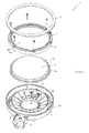
- Fig. 2 is an exploded perspective view of the electronic percussion instrument of Fig. 1.
- Fig. 3 is a plan view with the hoop taken off of the head of the electronic percussion instrument of Fig. 1.
- Fig. 4 is a cross-sectional view at a cross-section that includes the joining bolts of the electronic percussion instrument of Fig. 1.
- Fig. 5 is a cross-sectional view of a sensor part of the electronic percussion instrument of Fig. 1.
- An electronic percussion instrument 1 is an electronic percussion instrument referred to as an "electronic drum” that is played using sticks and the like, provided with sensors that detect vibrations due to hits.
- Music note equipment (not shown) controls a sound source based on the signals detected by the sensors and is designed so as to generate musical notes or sounds in proportion to the hits.
- the musical notes or sounds are output from speaker equipment via amplifier equipment.
- Fig. 1 is an external perspective view of an electronic percussion instrument 1 according to one embodiment of the present invention.
- the exterior of electronic percussion instrument 1, as shown in Fig. 1 is provided with a body part 2, a rim cover 3, a hoop 4, and a head 5.
- Fig. 2 is an exploded perspective view that shows these parts in a disassembled state.
- tension is applied to the head 5 and it is fixed in place.
- the rim cover 3 is fit onto the outer circumferential part 2a of the body part 2.
- the body part 2 forms a framework of the electronic percussion instrument 1 and, in the embodiment shown in Fig. 2, is formed in an approximately hollow cylindrical shape from a resin material.
- the outer circumference of the body part 2 is formed in a cylindrical shape with the outer circumferential part 2a erected almost vertically from the bottom part 2g (refer to Fig. 4).
- the rim cover in this embodiment, is fit on the periphery of the upper edge of the outer circumferential part 2a forming the rim part.
- a head support member 2b is formed as one unit with the bottom part 2g and the outer circumference part 2a, and is arranged in a standing manner from the bottom part 2g.
- the unit forms a cylindrical shape of concentric circles with the outer circumference part 2a.
- the head support member 2b is supported by a plurality of ribs 2d, in this embodiment, arranged in a standing manner perpendicular to the bottom part 2g.
- the ribs 2d are formed in the body part 2 as shapes radiating from the central direction of the cylinder. Furthermore, in the central part of the cylinder of the bottom part 2g, at least one circular hole 2h is formed and the air inside the body part 2 can freely go outside.
- the lower surface of the head 5 contacts the upper edge circumference of the head support member 2b, and the ring shaped hoop 4 surrounds the outer circumference of the head while imparting tension to the head 5.
- the rim cover 3 in this embodiment, comprises a cylindrical shaped cover made of rubber, soft plastic, or the like, fit onto the upper edge of the perimeter of the body part 2.
- the rubber makes hitting the rim with the shaft and the like of a stick feel softer because the rubber covering is more flexible than the body part 2, which is made of hard resin.
- the rim part corresponds to the part comprising the rim cover 3 and the outer circumference part 2a.
- the hoop 4 in this embodiment, comprises the bolt holes 4b into which the joining bolts 7 are inserted, and the bolt head accommodating holes 4c (or recesses) that receive the heads of the joining bolts 7.
- the bolt holes 4b and bolt head accommodating holes 4c divide the circumference of the hoop 4 into a plurality (for example six) equal parts on the hoop main body 4a that contacts the ring shaped head framework 5b of the head 5.
- internal threads 2e into which the joining bolts 7 are screwed, are positioned on the bottom of the head part 2, between the head support member 2b and the outer circumference part 2a, dividing the circumference of the head part 2 into a plurality (for example six) equal parts (refer to Fig. 3).
- the head 5, in this embodiment, comprises a hitting surface member 5a comprising of film shaped material formed from synthetic resin and a mesh shaped material knitted out of synthetic fibers bonded to a head framework 5b.
- the head framework 5b has a ring shape and is composed of a metal material or the like.
- the hitting surface member 5a is hit by sticks and the like.
- the joining bolts 7, in this embodiment, are made of steel, join the hoop 4 to the body part 2 by screwing them together, and impart tension to the head 5 through the hoop 4.
- the head 5 is sandwiched between the hoop 4 and the head support member 2b providing support.
- the tension imparted to the head 5 can be adjusted by tightening the joining bolts 7. Furthermore, when a rim shot takes place, because the upper edge of the outer circumferential part 2a is hit and the hoop is not hit directly, the joining bolts 7 do not loosen.
- the body part 2 in one embodiment, has an attaching part 2c protruding from the body for attaching a stand and the like (Fig. 2 lower part).
- a rod hole 2f for receiving a rod-shaped support portion of a stand is inserted therein.
- a mechanism such as a threaded set screw may extend into the hole 2f to frictionally engage the inserted rod and inhibit relative movement between the rod and the body part 2.
- a handle 8 may be provided for allowing a user to manually drive that mechanism. This handle is devised so that, when it is turned to the right the rod inserted into the rod hole 2f is held and, when it is turned to the left the rod is released.
- a head sensor 21 and a rim sensor 31, in one embodiment, are positioned in the inner side of the cylinder that the head support member 2b forms, opposite the attaching part 2c.
- the central axis of the cylinder that the body part 2 forms is between the attaching part 2c and the head sensor 21 and rim sensor 31.
- the head sensor 21 is bonded to the top of the support plate 11 extending above two supports positioned in a standing manner with respect to the bottom 2g (refer to Fig. 3), and the rim sensor 31 is bonded to the bottom part 2g.
- Fig. 3 is a plan view that shows an electronic percussion instrument 1, when the hoop 4 and the head 5 are removed.
- a stereo jack 9 is provided in order to output the electric signals detected by the head sensor 21 and the rim sensor 31.
- the electric signals detected by the head sensor 21 and the rim sensor 31 are each independently output by means of a stereo plug inserted into this stereo jack.
- Fig. 4 is a cross-sectional view, cut at a plane perpendicular to the hitting surface 5a of the head 5, through the shaft centers of joining bolts 7 of an electronic percussion instrument 1.
- Fig. 4(a) is the plan view that shows the position of the cross-section shown in Fig. 4(b), and Fig. 4(b) is that cross-sectional view.
- the rim cover 3 is mated to the upper edge of the body part 2, and the hitting surface 5a is placed lower than the upper edge of that rim cover.
- the head framework 5b contacts the hoop main body 4a, and the hoop 4 is pressed down by screwing joining bolts 7 into the internal threads 2e.
- the upper surface of the head 5 and the upper surface of the hoop 4 are approximately flush when assembled. Therefore the hitting surface looks uniform at the upper surface of the head 5 and the upper surface of the hoop 4, making the player feel like the hitting area is larger and therefore easier to play.
- the bolt holes 4b into which the joining bolts 7 are inserted divide the circumference of the hoop 4 into a plurality (such as six) equal divisions in this embodiment.
- the hitting surface member 5a is made of a mesh material bonded to a head framework 5b that has a ring shape. As shown in Fig. 4, since the head framework 5b is fit onto the outer circumference of the head support member 2b, the hitting surface member 5a extends to the upper edge surface (Fig. 4 upper side) of the body part 2. The head sensor 21 contacts the bottom surface (Fig. 4 lower side surface) of the extended hitting surface member 5a.
- the air resistance of the hitting surface is reduced.
- the hitting surface feels better when hit by means of sticks and the like, yet the acoustic sound emanating from the hitting surface is reduced, for example, so only the musical note from the speaker equipment may be heard by the player.
- heads made of multiple layers of mesh material are described in U.S. Patent No. 5,920,026 , which is incorporated herein by reference.
- Other suitable mesh head materials have been sold in the United States by Roland Corporation with and for certain products in Roland's V-drumTM line of electronic percussion instruments.
- the vibrations of the hitting surface member 5a due to a hit propagate only within the hitting surface member 5a, the influence of that vibration is not substantially imparted to the body part 2. Therefore, such vibrations of the hitting surface member 5a are only detected by the head sensor 21 and are not mistakenly detected by the rim sensor 31. Furthermore, the tension of the hitting surface member 5a can be arbitrarily adjusted to accommodate the playing method of the user by changing the degree to which the jointing bolts 7 are screwed into the internal threads 2e.
- Fig. 5(a) is a plan view that shows the position of the cross-section shown in Fig. 5(b), and Fig. 5(b) is that cross-sectional view.
- the head sensor 21 comprises a sensor device used for detecting the vibrations of the head 5 and, in one embodiment, comprises a piezoelectric device 22 and cushioned double-sided tape.
- the piezoelectric device 22 and the like may be covered by a cushion member 23.
- the piezoelectric device 22 is a vibration detection sensor that converts piezo and the like vibrations to electric signals.
- the piezoelectric device 22 may be formed in a disk shaped body and has an output signal line (not shown).
- the upper and lower surfaces of the piezoelectric device 22, the cushioning member 23, and the cushioned double-sided tape are each attached by a suitable adhesive material.
- the output signal line is connected to the stereo jack 9 (refer to Fig. 3), and the electric signal from the piezoelectric device 22 may be output to a musical note device (not shown) via the stereo jack 9.
- the cushioned double-sided tape in a preferred embodiment, has adhesive material for adhering the piezoelectric device 22 to the support plate 11 and comprises double-sided tape with an adhesive layer laminated on the upper and lower surfaces of a cushioning layer.
- the cushioned double-sided tape is formed in approximately a disk shape, and the piezoelectric device 22 is stuck to the support plate 11 by means of this cushioned double-sided tape.
- the cushion member 23 transmits vibrations from the head 5 to the piezoelectric device 22.
- the cushion member 23 may comprise an approximately cylindrical shaped elastic member made of polyurethane foam or other suitable sponge-like material, or the like.
- the cushion member 23 is stuck to the piezoelectric device 22 and in one embodiment has a diameter larger than that of the piezoelectric device 22.
- the cushion member is positioned so that the upper surface of the cylindrically shaped body of the cushion member contacts the lower surface of the head 5 (hitting surface member 5a).
- a head sensor 21 may be secured to the top of a support member 11 by cushioned double-sided tape, with the upper surface of the cushion member 23 in contact with the lower surface of the head.
- the rim sensor 31 in one embodiment, comprises a sensing device used to detect the vibrations of the outer circumferential part 2a of the body part 2 and, similar to the above mentioned embodiment of the head sensor 21, has a piezoelectric device as a vibration detection sensor and cushioned double-sided tape for the purpose of securing the piezoelectric device to the bottom part 2g.
- a piezoelectric device as a vibration detection sensor and cushioned double-sided tape for the purpose of securing the piezoelectric device to the bottom part 2g.
- the rim sensor 31 is secured to the upper side of the bottom part 2g by means of cushioned double-sided tape.
- the secured position of this rim sensor 31 is in the vicinity of the head sensor 21 and is a position on the side opposite the attaching part 2c with the central axis of the cylinder that forms the body part 2 interposed in between.
- the rim part formed in the body part 2 does not have to impart tension to the head 5 (which is provided by a hoop 4 that is a separate member), so the height of the upper edge of the rim part from the upper surface of the head 5 may be uniform and constant. Therefore a rim shot can more easily be played.
- the vibration from a rim shot propagated to the head 5 may be mistakenly detected by the head sensor.
- the rim part does not directly touch the head 5, preventing false detection of a rim shot by the head sensor.
- the rim part comprises a rubber rim cover 3 that fits on to the outer circumferential part 2a but the rim cover 3 may also be omitted.
Landscapes
- Physics & Mathematics (AREA)
- Engineering & Computer Science (AREA)
- Acoustics & Sound (AREA)
- Multimedia (AREA)
- Electrophonic Musical Instruments (AREA)
Applications Claiming Priority (2)
| Application Number | Priority Date | Filing Date | Title |
|---|---|---|---|
| JP2006076442A JP2007249141A (ja) | 2006-03-20 | 2006-03-20 | 電子打楽器 |
| JP2006076441A JP4721936B2 (ja) | 2006-03-20 | 2006-03-20 | 電子打楽器 |
Publications (2)
| Publication Number | Publication Date |
|---|---|
| EP1837860A2 true EP1837860A2 (de) | 2007-09-26 |
| EP1837860A3 EP1837860A3 (de) | 2007-11-14 |
Family
ID=38229731
Family Applications (1)
| Application Number | Title | Priority Date | Filing Date |
|---|---|---|---|
| EP07104427A Withdrawn EP1837860A3 (de) | 2006-03-20 | 2007-03-19 | Elektronisches Schlagzeuginstrument |
Country Status (2)
| Country | Link |
|---|---|
| US (1) | US7612273B2 (de) |
| EP (1) | EP1837860A3 (de) |
Cited By (13)
| Publication number | Priority date | Publication date | Assignee | Title |
|---|---|---|---|---|
| US20140069265A1 (en) * | 2012-09-12 | 2014-03-13 | Ai-Musics Technology Inc. | Electric Drum And Cymbal With Spider Web-Like Sensor |
| US20140260921A1 (en) * | 2013-03-12 | 2014-09-18 | Yamaha Corporation | Electronic percussion instrument |
| US9053694B2 (en) | 2013-03-12 | 2015-06-09 | Yamaha Corporation | Electronic percussion instrument |
| US9129585B2 (en) | 2013-03-12 | 2015-09-08 | Yamaha Corporation | Electronic percussion instrument |
| US9153220B2 (en) | 2013-03-12 | 2015-10-06 | Yamaha Corporation | Electronic percussion instrument |
| US9460699B2 (en) | 2013-03-12 | 2016-10-04 | Yamaha Corporation | Electronic percussion instrument |
| CN107851427A (zh) * | 2015-09-04 | 2018-03-27 | 罗兰株式会社 | 低音大鼓用消音件及低音大鼓 |
| USD1023131S1 (en) * | 2022-04-24 | 2024-04-16 | Ningbo Kinlin Electronic Technology Co., Ltd. | Drum |
| USD1042882S1 (en) * | 2023-12-26 | 2024-09-17 | Iromascents A.B. Ltd. | Modular drum |
| USD1051982S1 (en) * | 2023-12-28 | 2024-11-19 | Ningbo Kinlin Electronic Technology Co., Ltd. | Drum |
| EP4485447A1 (de) * | 2023-06-29 | 2025-01-01 | Roland Corporation | Schlaginstrument und zugkraftanwendungsverfahren dafür |
| USD1087213S1 (en) * | 2023-07-06 | 2025-08-05 | Roland Corporation | Electronic percussion instrument |
| USD1092608S1 (en) * | 2023-07-06 | 2025-09-09 | Roland Corporation | Electronic percussion instrument |
Families Citing this family (28)
| Publication number | Priority date | Publication date | Assignee | Title |
|---|---|---|---|---|
| US9343048B2 (en) * | 2005-05-16 | 2016-05-17 | James Frederick Shepherd | Drum rim raising device with a piezoelectric sensor and a force sensor |
| JP5067214B2 (ja) * | 2008-03-13 | 2012-11-07 | ヤマハ株式会社 | 電子打楽器 |
| SE532779C2 (sv) * | 2008-08-28 | 2010-04-06 | 2Box Ab | Spännsargsarrangemang till ett slaginstrument |
| USD616017S1 (en) * | 2008-10-29 | 2010-05-18 | Famous Drum Company, Llc | Drum |
| JP5441507B2 (ja) * | 2009-06-11 | 2014-03-12 | ローランド株式会社 | ドラム用ブラケット |
| EP3366692A1 (de) * | 2009-06-22 | 2018-08-29 | Amgen, Inc | Proteinneufaltung mit einem chemisch gesteuerten redoxzustand |
| US8563843B1 (en) * | 2010-01-13 | 2013-10-22 | Guy Shemesh | Electronic percussion device and method |
| US8933310B2 (en) * | 2011-11-09 | 2015-01-13 | Rtom Corporation | Acoustic/electronic drum assembly |
| JP5897895B2 (ja) | 2011-12-14 | 2016-04-06 | ローランド株式会社 | 打楽器 |
| USD726247S1 (en) * | 2011-12-14 | 2015-04-07 | Roland Corporation | Electronic percussion instrument |
| JP2013142872A (ja) | 2012-01-12 | 2013-07-22 | Roland Corp | 電子打楽器 |
| US9099070B2 (en) * | 2012-09-12 | 2015-08-04 | Ai-Musics Technology Inc. | Electric drum and cymbal with spider web-like sensor |
| JP6399796B2 (ja) * | 2013-09-02 | 2018-10-03 | ローランド株式会社 | 打楽器およびその打楽器に用いられるドラムヘッド |
| US9390697B2 (en) | 2013-12-23 | 2016-07-12 | Pearl Musical Instrument Co. | Removable electronic drum head and hoop for acoustic drum |
| TWI643182B (zh) * | 2014-09-11 | 2018-12-01 | 功學社教育用品股份有限公司 | 具有蜘蛛網狀感測器之電子鼓及鈸 |
| US11308928B2 (en) | 2014-09-25 | 2022-04-19 | Sunhouse Technologies, Inc. | Systems and methods for capturing and interpreting audio |
| EP3198247B1 (de) | 2014-09-25 | 2021-03-17 | Sunhouse Technologies, Inc. | Vorrichtung zur erfassung von schwingungen von einem objekt, und system zur erfassung von schwingungen von einer trommel. |
| JP1550608S (de) * | 2015-07-10 | 2016-05-30 | ||
| US10679591B2 (en) * | 2016-12-21 | 2020-06-09 | Gewa Music Gmbh | Trigger tray for percussion instrument |
| KR20190107684A (ko) | 2017-01-17 | 2019-09-20 | 드럼 워크샵, 인크. | 전자 심벌 조립체 및 그의 구성요소 |
| TWM548340U (zh) * | 2017-05-24 | 2017-09-01 | Sound And Light Co Ltd | 可抑制音源雜訊的電子打擊樂器 |
| JP2019148623A (ja) * | 2018-02-26 | 2019-09-05 | ローランド株式会社 | 電子打楽器 |
| JP7194011B2 (ja) * | 2018-12-26 | 2022-12-21 | ローランド株式会社 | 打楽器および張力付与方法 |
| CN113129858B (zh) * | 2019-12-26 | 2026-04-17 | 罗兰株式会社 | 电子打击乐器以及打击检测方法 |
| CN114945976A (zh) * | 2020-01-20 | 2022-08-26 | 鼓工场有限公司 | 电子音乐乐器和系统 |
| JP2025524809A (ja) | 2022-07-21 | 2025-08-01 | ドラム ワークショップ, インコーポレイテッド | 電子楽器、システム、及び方法 |
| JP2025006380A (ja) * | 2023-06-29 | 2025-01-17 | ローランド株式会社 | 電子打楽器およびリムセンサの支持方法 |
| CN121620796A (zh) * | 2023-08-28 | 2026-03-06 | 罗兰株式会社 | 弹性体、鼓皮、打击乐器及弹性体的安装方法 |
Family Cites Families (39)
| Publication number | Priority date | Publication date | Assignee | Title |
|---|---|---|---|---|
| US3509264A (en) * | 1967-12-29 | 1970-04-28 | Allen J Green | Electric drum or other percussion instrument |
| US3659032A (en) * | 1971-06-25 | 1972-04-25 | Gordon H May | Percussion instrument |
| US4048895A (en) * | 1976-10-12 | 1977-09-20 | May Randall L | Adjustable pitch drum |
| US4168646A (en) * | 1978-07-24 | 1979-09-25 | May Randall L | Electro-acoustically amplified drum |
| US4242937A (en) * | 1979-02-08 | 1981-01-06 | Pozar Cleve F | Pickup assembly for percussion instrument |
| US4254685A (en) * | 1979-06-13 | 1981-03-10 | Rose Calvin D | Drum and drumhead structure |
| US4279188A (en) * | 1979-09-21 | 1981-07-21 | Scott Robert D | Acoustic coupling free electric drum |
| US4475434A (en) * | 1982-09-20 | 1984-10-09 | Willis Ward L | Quick release drum head assembly |
| JPS60159499U (ja) * | 1984-03-31 | 1985-10-23 | 星野楽器株式会社 | 電子ドラムのパツド |
| CA1264240A (en) * | 1985-03-13 | 1990-01-09 | Terry Paul Cleland | Percussion musical instrument drum-head tensioning assembly and drum shell constructin therefor |
| JPS636494U (de) * | 1986-06-30 | 1988-01-16 | ||
| JPH0715027Y2 (ja) * | 1986-10-14 | 1995-04-10 | ヤマハ株式会社 | 電子ドラム |
| US4798121A (en) * | 1987-05-27 | 1989-01-17 | Aquarian Accessories Corporation | Impact resistant drumhead |
| US4998960A (en) * | 1988-09-30 | 1991-03-12 | Floyd Rose | Music synthesizer |
| US5042356A (en) * | 1989-07-06 | 1991-08-27 | Karch Jeffrey M | Kit for converting a conventional drum into an electronically triggered drum |
| US5105710A (en) * | 1991-09-16 | 1992-04-21 | Steven Rothmel | Tuned electronic drum pad |
| US5430245A (en) * | 1993-01-14 | 1995-07-04 | Rtom Corporation | Electroacoustical drum |
| US6756535B1 (en) * | 1996-07-04 | 2004-06-29 | Roland Corporation | Electronic percussion instrumental system and percussion detecting apparatus therein |
| JP3695037B2 (ja) * | 1997-01-24 | 2005-09-14 | ヤマハ株式会社 | 電子打楽器 |
| US5915289A (en) * | 1997-12-12 | 1999-06-22 | Hart; Peter | Electronic cymbal apparatus |
| US6069307A (en) * | 1999-01-25 | 2000-05-30 | Rtom Corporation | Inflatable musical drum |
| JP3835084B2 (ja) * | 1999-11-15 | 2006-10-18 | ヤマハ株式会社 | ドラム、減音装置および電子打楽器用ヘッド |
| US6365812B1 (en) * | 2000-01-20 | 2002-04-02 | Dimension Polyant Sailcloth, Inc. | Drumhead material and method |
| WO2002065445A2 (en) * | 2001-02-12 | 2002-08-22 | Keith Le Blanc | Electronic drum |
| US6580023B2 (en) * | 2001-08-13 | 2003-06-17 | Remo, Inc. | Convertible drumhead |
| JP3644433B2 (ja) | 2001-09-27 | 2005-04-27 | ヤマハ株式会社 | 打撃検出装置及び電子打楽器 |
| EP1298641B1 (de) * | 2001-09-27 | 2009-02-18 | Yamaha Corporation | Einfaches elektronisches Musikinstrument, Spielerkonsole und eingebautes Signalverarbeitungssystem |
| US6686526B2 (en) * | 2001-10-17 | 2004-02-03 | Leonard E. Ezbicki | Percussion practice aid |
| US6949701B2 (en) * | 2002-01-18 | 2005-09-27 | Yamaha Corporation | Drumhead |
| JP3818203B2 (ja) * | 2002-04-05 | 2006-09-06 | ヤマハ株式会社 | 電子打楽器 |
| JP3680819B2 (ja) * | 2002-06-10 | 2005-08-10 | ヤマハ株式会社 | ドラム |
| US7074996B2 (en) * | 2002-08-08 | 2006-07-11 | Latin Percussion Inc. | Drum head assembly and method of tensioning a drum head |
| US6765139B2 (en) * | 2002-12-03 | 2004-07-20 | Belli Remo D | Drumhead and tensioning apparatus |
| JP3933566B2 (ja) | 2002-12-17 | 2007-06-20 | ローランド株式会社 | 電子打楽器および振動検出装置 |
| US6982376B2 (en) * | 2003-07-28 | 2006-01-03 | Wise Johnathan R | Real drum trigger monitor and amplified tone module |
| US7074994B2 (en) * | 2003-07-28 | 2006-07-11 | Remo, Inc. | Tunable drumhead |
| US20050109190A1 (en) * | 2003-11-26 | 2005-05-26 | Aviation Devices & Electronic Components, Inc. | Dampening material for a drum |
| JP4183626B2 (ja) * | 2004-01-08 | 2008-11-19 | ローランド株式会社 | 電子打楽器 |
| JP4144564B2 (ja) * | 2004-05-25 | 2008-09-03 | ヤマハ株式会社 | 電子ドラム |
-
2006
- 2006-09-01 US US11/514,805 patent/US7612273B2/en active Active
-
2007
- 2007-03-19 EP EP07104427A patent/EP1837860A3/de not_active Withdrawn
Cited By (17)
| Publication number | Priority date | Publication date | Assignee | Title |
|---|---|---|---|---|
| US8841527B2 (en) * | 2012-09-12 | 2014-09-23 | Al-Musics Technology Inc. | Electric drum and cymbal with spider web-like sensor |
| US20140069265A1 (en) * | 2012-09-12 | 2014-03-13 | Ai-Musics Technology Inc. | Electric Drum And Cymbal With Spider Web-Like Sensor |
| CN104050958B (zh) * | 2013-03-12 | 2018-04-06 | 雅马哈株式会社 | 电子打击乐器 |
| US20140260921A1 (en) * | 2013-03-12 | 2014-09-18 | Yamaha Corporation | Electronic percussion instrument |
| US9053694B2 (en) | 2013-03-12 | 2015-06-09 | Yamaha Corporation | Electronic percussion instrument |
| US9129585B2 (en) | 2013-03-12 | 2015-09-08 | Yamaha Corporation | Electronic percussion instrument |
| US9153220B2 (en) | 2013-03-12 | 2015-10-06 | Yamaha Corporation | Electronic percussion instrument |
| US9196237B2 (en) * | 2013-03-12 | 2015-11-24 | Yamaha Corporation | Electronic percussion instrument |
| US9460699B2 (en) | 2013-03-12 | 2016-10-04 | Yamaha Corporation | Electronic percussion instrument |
| CN107851427A (zh) * | 2015-09-04 | 2018-03-27 | 罗兰株式会社 | 低音大鼓用消音件及低音大鼓 |
| CN107851427B (zh) * | 2015-09-04 | 2021-12-28 | 罗兰株式会社 | 低音大鼓用消音件及低音大鼓 |
| USD1023131S1 (en) * | 2022-04-24 | 2024-04-16 | Ningbo Kinlin Electronic Technology Co., Ltd. | Drum |
| EP4485447A1 (de) * | 2023-06-29 | 2025-01-01 | Roland Corporation | Schlaginstrument und zugkraftanwendungsverfahren dafür |
| USD1087213S1 (en) * | 2023-07-06 | 2025-08-05 | Roland Corporation | Electronic percussion instrument |
| USD1092608S1 (en) * | 2023-07-06 | 2025-09-09 | Roland Corporation | Electronic percussion instrument |
| USD1042882S1 (en) * | 2023-12-26 | 2024-09-17 | Iromascents A.B. Ltd. | Modular drum |
| USD1051982S1 (en) * | 2023-12-28 | 2024-11-19 | Ningbo Kinlin Electronic Technology Co., Ltd. | Drum |
Also Published As
| Publication number | Publication date |
|---|---|
| US7612273B2 (en) | 2009-11-03 |
| EP1837860A3 (de) | 2007-11-14 |
| US20070234886A1 (en) | 2007-10-11 |
Similar Documents
| Publication | Publication Date | Title |
|---|---|---|
| US7612273B2 (en) | Electronic percussion instrument | |
| JP4183626B2 (ja) | 電子打楽器 | |
| US5293000A (en) | Electronic percussion system simulating play and response of acoustical drum | |
| US5811709A (en) | Acoustic drum with electronic trigger sensor | |
| JP3818203B2 (ja) | 電子打楽器 | |
| EP2261890B1 (de) | Schlaginstrumentensystem und -verfahren | |
| US9343048B2 (en) | Drum rim raising device with a piezoelectric sensor and a force sensor | |
| US7179985B2 (en) | Hybrid electric/acoustic percussion instrument | |
| JP2004198657A (ja) | 電子打楽器および振動検出装置 | |
| US7858859B2 (en) | Stand for a drum and also relating thereto | |
| US5977473A (en) | Acoustic drum with shell wall embedded electronic trigger sensor and head to shell sound transfer arm | |
| US9589552B1 (en) | Percussion instrument and cajon | |
| JP2013142872A (ja) | 電子打楽器 | |
| JP2012014003A (ja) | 打楽器用打撃検出装置 | |
| US9691366B2 (en) | Hybrid drum apparatus | |
| JP4721936B2 (ja) | 電子打楽器 | |
| JP2007249141A (ja) | 電子打楽器 | |
| JP2005274727A (ja) | 打楽器用パッド | |
| US7657051B1 (en) | Bass drum speaker | |
| JP2006259193A (ja) | 電子ドラムの取付構造 | |
| WO2009110838A1 (en) | Drum head for electronic percussion instrument | |
| JP4556894B2 (ja) | 電子打楽器装置 | |
| US12620374B2 (en) | Drum enhancement assembly | |
| US20240153473A1 (en) | Drum enhancement assembly | |
| EP3843082B1 (de) | Trommelkopf und befestigungverfahren von dämpfungsschichten |
Legal Events
| Date | Code | Title | Description |
|---|---|---|---|
| PUAI | Public reference made under article 153(3) epc to a published international application that has entered the european phase |
Free format text: ORIGINAL CODE: 0009012 |
|
| AK | Designated contracting states |
Kind code of ref document: A2 Designated state(s): AT BE BG CH CY CZ DE DK EE ES FI FR GB GR HU IE IS IT LI LT LU LV MC MT NL PL PT RO SE SI SK TR |
|
| AX | Request for extension of the european patent |
Extension state: AL BA HR MK YU |
|
| PUAL | Search report despatched |
Free format text: ORIGINAL CODE: 0009013 |
|
| AK | Designated contracting states |
Kind code of ref document: A3 Designated state(s): AT BE BG CH CY CZ DE DK EE ES FI FR GB GR HU IE IS IT LI LT LU LV MC MT NL PL PT RO SE SI SK TR |
|
| AX | Request for extension of the european patent |
Extension state: AL BA HR MK YU |
|
| 17P | Request for examination filed |
Effective date: 20080508 |
|
| 17Q | First examination report despatched |
Effective date: 20080609 |
|
| AKX | Designation fees paid |
Designated state(s): DE FR GB SE |
|
| STAA | Information on the status of an ep patent application or granted ep patent |
Free format text: STATUS: THE APPLICATION IS DEEMED TO BE WITHDRAWN |
|
| 18D | Application deemed to be withdrawn |
Effective date: 20110304 |