EP1838143A2 - Appareil de stockage - Google Patents
Appareil de stockage Download PDFInfo
- Publication number
- EP1838143A2 EP1838143A2 EP06255688A EP06255688A EP1838143A2 EP 1838143 A2 EP1838143 A2 EP 1838143A2 EP 06255688 A EP06255688 A EP 06255688A EP 06255688 A EP06255688 A EP 06255688A EP 1838143 A2 EP1838143 A2 EP 1838143A2
- Authority
- EP
- European Patent Office
- Prior art keywords
- area
- external air
- cabinet
- storage apparatus
- cooling
- Prior art date
- Legal status (The legal status is an assumption and is not a legal conclusion. Google has not performed a legal analysis and makes no representation as to the accuracy of the status listed.)
- Withdrawn
Links
Images


Classifications
-
- G—PHYSICS
- G11—INFORMATION STORAGE
- G11B—INFORMATION STORAGE BASED ON RELATIVE MOVEMENT BETWEEN RECORD CARRIER AND TRANSDUCER
- G11B33/00—Constructional parts, details or accessories not provided for in the other groups of this subclass
- G11B33/14—Reducing influence of physical parameters, e.g. temperature change, moisture, dust
- G11B33/1406—Reducing the influence of the temperature
- G11B33/1413—Reducing the influence of the temperature by fluid cooling
- G11B33/142—Reducing the influence of the temperature by fluid cooling by air cooling
-
- H—ELECTRICITY
- H05—ELECTRIC TECHNIQUES NOT OTHERWISE PROVIDED FOR
- H05K—PRINTED CIRCUITS; CASINGS OR CONSTRUCTIONAL DETAILS OF ELECTRIC APPARATUS; MANUFACTURE OF ASSEMBLAGES OF ELECTRICAL COMPONENTS
- H05K7/00—Constructional details common to different types of electric apparatus
- H05K7/20—Modifications to facilitate cooling, ventilating, or heating
- H05K7/20709—Modifications to facilitate cooling, ventilating, or heating for server racks or cabinets; for data centers, e.g. 19-inch computer racks
- H05K7/20718—Forced ventilation of a gaseous coolant
- H05K7/20736—Forced ventilation of a gaseous coolant within cabinets for removing heat from server blades
Definitions
- the present invention generally relates to a high-density mounting storage apparatus housing numerous memory mediums in a cabinet, and in particular but not exclusively relates to a storage apparatus having a configuration for improving the cooling capability in the cabinet.
- a part of the power supplied to a hard disk drive in an electronic apparatus is converted into frictional heat caused by the rotation of the hard disk or resistance heat of an electronic circuit.
- a storage apparatus having a plurality of hard disk drives arranged in an array, the denser these hard disk drives are mounted, the higher the heating value.
- the storage apparatus is being operated, it is necessary to cool the hard disk drives and electronic circuits in the storage apparatus.
- a magnetic disk device configured by including in a single apparatus cabinet a plurality of magnetic disk drives for magnetically storing information, a control circuit board mounted with a control circuit for controlling such magnetic disk drives, and a ventilation means for cooling the magnetic disk drives and control circuit board with air cooling, wherein the magnetic disk drives, control circuit board and ventilation means are retained in a frame to configure a single disk box, and a plurality of such disk boxes are housed in a single apparatus cabinet.
- Japanese Patent Laid-Open Publication No. 2005-19562 describes a storage apparatus including a ventilation unit provided on a ceiling of a cabinet for ventilating the interior and exterior of the cabinet, a hollow duct having two opening surfaces and arranged in a first housing unit for housing a first electronics device housing box formed at a level on the side near the ceiling so that the first opening surface faces the ventilation unit, a second opening surface faces a second housing unit for housing a second electronics device housing box formed at a level on the side far from the ceiling, air inside the second electronics device housing box housed in the second housing unit is discharged from the ventilation unit outside the cabinet through the interior of the duct, and air in the first electronics device housing box housed in the first housing unit is discharged from the ventilation unit outside the cabinet along the outer wall surface of the duct.
- Japanese Patent Laid-Open Publication No. H8-273345 proposes providing a ventilation means to each disk box for cooling each disk unit, no consideration is given to streamlining the exhaust air or miniaturizing the fan.
- the present invention was devised in view of the foregoing problems, and an object thereof is to inhibit the noise generated by the fan upon cooling the storage apparatus, and inhibit the electricity consumption required for such cooling.
- an aspect of the present invention is characterized in that the flow of external air for cooling the first housing unit and the flow of external air for cooling the second housing unit are not mixed in the storage apparatus.
- an aspect of the present invention provides a storage apparatus having in a cabinet, and arranged in one direction, a memory medium housing unit for storing a plurality of memory mediums, a control unit for performing data I/O processing to the memory mediums in response to a data I/O request from an upper-level host system, and a power supply unit for supplying power to the memory medium housing unit and the control unit, including: a plurality of cooling areas formed in the cabinet; an external air introduction/discharge device for directing external air to the respective cooling areas, and thereafter discharging the external air from a discharge area of the cabinet outside the cabinet; and an external air guidance area for guiding the external air that passed through each of the cooling areas to the discharge area; wherein the external air guidance area is configured so that the external air that passed through one cooling area will not get mixed with the external air that passed through another cooling area.
- FIG. 1 is a perspective view showing the overall storage apparatus.
- the storage apparatus 100 is configured by housing, in a cabinet 200 forming a large rectangular shape, a DC power supply 600, a battery 800, an LG box (control unit) 400 and an HDD box 300 from the ground plane side of the cabinet toward the top side of the cabinet in that order.
- An upper-level system not shown (a host system for example) is connected to the storage apparatus illustrated in FIG. 1, and data to be accessed by the host system is stored in the hard disk drive in the HDD box 300.
- Each HDD box 300 has a plurality of hard disk drives 300A arranged in an array.
- the LG box 400 has a control circuit for controlling the input and output of data between the host system and storage apparatus.
- the DC power supply 600 converts AC power into DC power, and supplies DC power to the LG box and HDD box.
- the battery 800 is a standby power supply device.
- FIG. 2 is a perspective view showing a state where the respective units are housed in the cabinet 200 of the storage apparatus 100.
- the foregoing HDD box 300 is housed in the upper row of the storage apparatus 10.
- the hard disk drive 300A in the HDD box 300 is insertably and removably housed in the HDD box.
- Electric fans 500 are provided at the top face of the storage apparatus. These electric fans guide the external air from outside the cabinet toward the center of the cabinet via the HDD box, and discharge this external air from the top of the storage apparatus.
- a total of 64 disk drives 310 are loaded in an array in the HDD box 300; 4 rows in the direction of gravitational force, and 16 rows in a direction perpendicular to the vertical direction.
- a plurality of frames are assembled to form a rectangular shape so as to configure the overall cabinet 200, and the upper row, middle row and lower row of the cabinet are formed with partition frames 201, 202.
- the HDD box 300 is supported above the partition frame 201.
- the control unit 400 is being supported and fixed by the partition frame 202 in the middle row formed between the partition frame 201 and partition frame 202.
- the DC power supply 600, battery 800 and AC box 700 are housed in the lower row formed between the partition frames and the frame 203 at the bottom of the cabinet.
- the LG box (control unit) 400 has a plurality of logical substrates 430 with a control circuit formed thereon.
- the logical substrate 430 is insertably and removably housed in the LG box.
- the logical substrate 430 includes a channel adapter for performing communication between the storage apparatus 100 and information processing device in order to input and output data, a disk adapter for performing I/O processing of data stored in the disk drive 300A, and a cache memory for storing data sent to and received from the information processing device.
- Electric fans 410 for drawing in external air from the outside to inside of the cabinet are provided to the top face of the LG box 400. These electric fans guide external air into the cabinet via the power supply unit and LG box, and then discharge such external air outside the cabinet.
- the battery 800, AC box 700 and DC power supply 600 are housed inside the lower row of the cabinet 200. These integrally form the power supply unit of the storage apparatus. By disposing the heavy power supply unit in the lower row of the storage apparatus 100, it is possible to stabilize the storage apparatus upon grounding the storage apparatus. Incidentally, as shown in FIG. 1, an operational input unit 100A is provided to the front side of the storage apparatus.
- the DC power supply 600 converts AC power into DC power, and supplies DC power to the LG box 400 and disk drive 310.
- the battery 800 supplies backup powder to the respective components inside the storage apparatus 100 during a blackout or failure in the DC power supply 600.
- the AC box 700 is an intake of AC power to the storage apparatus 100, and functions as a breaker. AC power introduced into the AC box 700 is supplied to the DC power supply 600.
- the significant heating value generated by the power supply unit in the lower row of the storage is cooled by the external air supplied into the cabinet with the electric fans 410.
- a pair of HDD boxes 300, LG boxes 400 and power supply units are respectively disposed and housed in the storage apparatus; one from the front side and one from the back side of the storage apparatus.
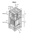
- FIG. 3 is a perspective view of the overall storage apparatus for showing the cooling system of the storage apparatus.
- the cooling area of the storage apparatus is broadly separated into two sections; in other words, the cooling area is configured from an area 212 for cooling the HDD box 300, and an area 214 for cooling the LG box 400 and power supply unit 410A.
- the electric fan 500 aspirates the external air 216 from the outside to inside of the cabinet via the HDD box. This external air is discharged outside the storage apparatus 100 as exhaust air 218 by the electric fan 500.
- the external air 216 passes through the vicinity of the hard disk drive while flowing from the outside to inside of the cabinet so as to cool the hard disk drive.
- the electric fan 410 explained with reference to FIG. 2 aspirates the external air 220 from the outside to inside of the cabinet via the LG box 400 and power supply unit 410A, and this external air rises in the cabinet, passes through a space 222 formed between the HDD box and side face of the cabinet, and is discharged outside the cabinet as exhaust air 224.
- the external air guidance route or external air guidance area from the external air being introduced as intake air 216 and thereafter discharged outside the cabinet as exhaust air 218, and the route or area from the external air being introduced as intake air 220 and thereafter discharged outside the cabinet as exhaust air 224 from the left and right side faces of the cabinet are formed so that the external air of the former and external air of the latter do not get mixed. In other words, it is possible to substantially avoid the external air 220 from becoming the external air for cooling the HDD box.
- a decorative panel 230 is provided around the cabinet 200.
- the decorative panel although not shown, is provided with a plurality of openings for introducing external air.
- a ventilation space is formed between the decorative panel 230 and cabinet 200.
- the external air is aspirated into the storage apparatus from the front side, back side, right side and left side of the storage apparatus.
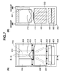
- FIG. 5 is a perspective view showing this configuration.
- a pair of HDD boxes 300 is housed inside the storage apparatus respectively from the front side and back side of the storage apparatus.
- a structure 210 substantially differentiating the introduction route of the intake air 220 passing through the cabinet as shown in FIG. 3 from the introduction route of the external air 216 passing through the cabinet.
- the introduction route of external air in the cabinet will be as shown in FIG. 6A and 6B, and FIG. 7A and 7B.
- FIG. 6A and 6B although this partially overlaps with the explanation of FIG.
- intake air 216 enters the structure 210 from the front side and left/right sides of the HDD box, and is discharged outside the cabinet as exhaust air 218 with the fan 500 in the exhaust air area of the storage apparatus.
- the structure 210 is formed in a rectangular shape where the planar surface and inside are opened.
- the bottom face of the structure 210 is shielded so that the external air 220 (refer to FIG. 7) will not enter the structure. This is the same for the left and right sides of the structure 210.
- the structure 210 is configured by including a bottom face 210A, left and right side faces 210C, and a frame 210B for forming the overall structure in a rectangular shape.
- a panel 330 is fixed to the frame 210B. This panel, as shown in FIG. 5, is facing the HDD box.
- a plurality of openings 330A are formed on the panel 330 to allow external air to enter into the structure 210.
- the density of forming such openings is formed so as to increase toward the lower end of the structure 210 (toward the bottom face of the storage apparatus) (refer to FIG. 8B).
- the structure 210 is configured such as the upper part thereof is formed in an open box shape, a fan 500 is provided to the upper part of the structure, and a fan 410 is also provided facing downward toward the bottom of the structure 10 so as to separate the external air. Therefore, the noise generated during the operation of the fan can be reduced, and it is possible to discharge external air efficiently.
- the intake air 220 was mixed with the intake air 216 in the cabinet, and the mixed external air was collectively discharged with the fan 500.
- the fan 500 there was no choice but to enlarge the fan 500.
- the power consumption and noise of the fan would increase.
- the enlargement of the axis for rotating the wings of the fan would shield the air passage, by miniaturizing the fan, such fan can be installed in accordance with the area of the passage.
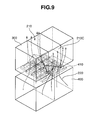
- inclined faces 213A and 213B are formed from the front side end 211A and back side end 211B of the bottom face 210A toward the center of the structure 210 at the left and right sides of the bottom face 210A of the structure 210.
- a ridge line 213D is formed from the center 215A of the bottom face 210A so as to connect the inclined faces 213A and 213B and an intersection 213C.
- a pair of semitriangular cone-shaped concave portions 217 is formed from the center of the structure to the left and right sides, respectively.
- Outside air 220 is force fed to the structure 210 side with the fan 400, thereafter comes in contact with the bottom face 210A of the structure 210, and directed to the left and right side faces 210C of the structure along the concave portion 217.
- the width of this concave portion since the concave portion is of a triangular cone shape, the width of the concave portion gradually becomes larger from the center of the structure toward the left and right sides, and external air 220 is directed smoothly to from the center of the structure to the left and right sides. In other words, external air 220 is directed smoothly from the center of the structure to the left and right sides with the pair of concave portions 217 formed from the center of the structure toward the left and right sides.
- the structure 210 is configured to have a concave portion so that the exhaust air from the LG box flows toward a direction in which the HDD box is not installed; that is, in a direction toward the side face. Further, the inclined faces 213A, 213B are able to direct external air from the front side and back side of the structure to the center of the structure. The flow of this external air is shown in FIG. 9.
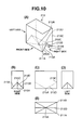
- FIG. 11A to 11 D show the measurements of the structure.
- One side on the front side of the bottom face of the structure is L, one side on the side face is D, and the height of the structure is H.
- the intermediate point of the front side end 211A and back side end 211B of the bottom face of the structure is 211 D.
- the length from 211 A to 211 D is d, the length from 211 D to the center 215A of the bottom face 210A is I, and the length from 211 D to 213C is h.
- the structure is formed to satisfy the relationship of: 0 ⁇ L - 2 ⁇ l L / 2 0 ⁇ d ⁇ D / 2 0 ⁇ h ⁇ H
- This structure is formed from metal, resin or Styrofoam.
- the size of L - 21 may be larger than 0.
- the apex of the semitriangular concave portion 217 does not have to be formed at the single point of 215A, and there may be several apexes as shown with 215B and 215C, and the space between such apexes may be distant.
- 211 C may be provided at a position that is more inside than the front side end 211A of the bottom face
- 211 E may be provided at a position that is more inside than the back side end 211B of the bottom face, respectively, and the concave portion 217 may be formed from such 211 C and 211 D toward the center of the structure.
- length a or b from 211 C or 211 E to 211 D may be formed shorter than one side D/2 on the side of the bottom face of the structure 210 so that a, b ⁇ D/2.
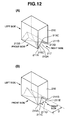
- the ridge line 213D formed from the center 215A of the bottom face 210A so as to connect the inclined faces 213A, 213B and the intersection 213C, for instance, as shown in FIG. 13, may also be a curved line.
- one side on the front side of the bottom face of the structure is L
- one side on the side face is D
- the height of the structure is H.
- the intermediate point of the front side end 211A and back side end 211B of the bottom face of the structure is 211 D.
- the length from 211A to 211 D is d
- the length from 211 D to the center 215A of the bottom face 210A is I
- the length from 211 D to 213C is h.
- the structure is formed to satisfy the relationship of: 0 ⁇ L - 2 ⁇ l ⁇ L / 2 0 ⁇ d ⁇ D / 2 0 ⁇ h ⁇ H
- the structure is formed to satisfy the relationship of 0° ⁇ ⁇ , ⁇ , ⁇ , ⁇ , ⁇ 90°.
- the shape of the concave portion 217 formed on the bottom face of the structure 210 does not necessarily have to be a shape similar to a cone shape, and, as shown in FIG. 14, may be configured by combining various shapes such as an oval shape or circular shape.
- the ridge line 213D formed so as to connect the inclined faces 213A, 213B and the intersection 213C does not necessarily have to be a straight line, and may also be a flux line, curved line, or formed in a staircase pattern.
- the ridge line 213D does not necessarily have to be a symmetrical line profile.
- the shape of the cut area of the concave portion 217 appearing on the side face 210C of the structure 210 does not necessarily have to be triangular, and, as shown in FIG. 15, may be a semi oval shape or circular shape, and there is no particular limitation in the shape of the cut area so as long as the concave portion has some kind of depression.
- the cut area does not necessarily have to take on a symmetrical shape on both side faces.
Landscapes
- Engineering & Computer Science (AREA)
- Computer Hardware Design (AREA)
- General Engineering & Computer Science (AREA)
- Physics & Mathematics (AREA)
- Thermal Sciences (AREA)
- Microelectronics & Electronic Packaging (AREA)
- Cooling Or The Like Of Electrical Apparatus (AREA)
Applications Claiming Priority (1)
| Application Number | Priority Date | Filing Date | Title |
|---|---|---|---|
| JP2006083445A JP2007257792A (ja) | 2006-03-24 | 2006-03-24 | ストレージ装置 |
Publications (2)
| Publication Number | Publication Date |
|---|---|
| EP1838143A2 true EP1838143A2 (fr) | 2007-09-26 |
| EP1838143A3 EP1838143A3 (fr) | 2009-12-09 |
Family
ID=38328402
Family Applications (1)
| Application Number | Title | Priority Date | Filing Date |
|---|---|---|---|
| EP06255688A Withdrawn EP1838143A3 (fr) | 2006-03-24 | 2006-11-03 | Appareil de stockage |
Country Status (3)
| Country | Link |
|---|---|
| US (1) | US7914366B2 (fr) |
| EP (1) | EP1838143A3 (fr) |
| JP (1) | JP2007257792A (fr) |
Families Citing this family (14)
| Publication number | Priority date | Publication date | Assignee | Title |
|---|---|---|---|---|
| US7857688B1 (en) * | 2006-12-11 | 2010-12-28 | Emc Corporation | Electrical cabinet having multi-channel exhaust with bleeding vents to alleviate back-pressure |
| US8182319B2 (en) * | 2008-12-10 | 2012-05-22 | Oracle America Inc. | Computer chassis fan modules providing vibration isolation and pinch release |
| US9696046B2 (en) * | 2010-03-26 | 2017-07-04 | Trane International Inc. | Modular air handling unit |
| US9759446B2 (en) | 2010-03-26 | 2017-09-12 | Trane International Inc. | Air handling unit with integral inner wall features |
| US10139115B2 (en) * | 2010-03-26 | 2018-11-27 | Trane International Inc. | Air handling unit with inner wall space |
| JP5464158B2 (ja) * | 2011-03-08 | 2014-04-09 | 株式会社安川電機 | 制御装置 |
| TW201242483A (en) * | 2011-04-06 | 2012-10-16 | Hon Hai Prec Ind Co Ltd | Data center |
| JP5339492B2 (ja) * | 2011-07-15 | 2013-11-13 | 日本電気株式会社 | 蓄電装置 |
| WO2012083698A1 (fr) * | 2011-08-01 | 2012-06-28 | 华为技术有限公司 | Dispositif et système de suppression de bruit de ventilation |
| US20130100610A1 (en) * | 2011-10-19 | 2013-04-25 | Danfoss A/S | Air duct arrangement for cooling a group of at least two heat producing modules |
| JP6007641B2 (ja) * | 2012-07-27 | 2016-10-12 | 株式会社豊田自動織機 | 電池パック |
| CN104603881B (zh) * | 2012-10-18 | 2017-03-08 | 株式会社日立制作所 | 存储装置和所述存储装置的存储控制器 |
| US10026454B2 (en) * | 2015-04-28 | 2018-07-17 | Seagate Technology Llc | Storage system with cross flow cooling of power supply unit |
| US20190357390A1 (en) * | 2018-05-18 | 2019-11-21 | Nokia Solutions And Networks Oy | Fan apparatuses for chassis airflow |
Family Cites Families (5)
| Publication number | Priority date | Publication date | Assignee | Title |
|---|---|---|---|---|
| US5136464A (en) * | 1990-04-20 | 1992-08-04 | Kabushiki Kaisha Toshiba | Housing structure for housing a plurality of electric components |
| JPH04226098A (ja) * | 1990-04-20 | 1992-08-14 | Toshiba Corp | 複数の電気用品を収納するためのハウジング構造体 |
| JPH08273345A (ja) * | 1995-03-31 | 1996-10-18 | Hitachi Ltd | 磁気ディスク装置 |
| JPH09274791A (ja) * | 1996-04-03 | 1997-10-21 | Hitachi Ltd | 磁気ディスク装置および電子装置 |
| JP2005019562A (ja) * | 2003-06-24 | 2005-01-20 | Hitachi Ltd | 電子機器の冷却構造 |
-
2006
- 2006-03-24 JP JP2006083445A patent/JP2007257792A/ja active Pending
- 2006-05-22 US US11/437,693 patent/US7914366B2/en not_active Expired - Fee Related
- 2006-11-03 EP EP06255688A patent/EP1838143A3/fr not_active Withdrawn
Also Published As
| Publication number | Publication date |
|---|---|
| JP2007257792A (ja) | 2007-10-04 |
| EP1838143A3 (fr) | 2009-12-09 |
| US7914366B2 (en) | 2011-03-29 |
| US20070220912A1 (en) | 2007-09-27 |
Similar Documents
| Publication | Publication Date | Title |
|---|---|---|
| US7643285B2 (en) | Storage apparatus | |
| EP1838143A2 (fr) | Appareil de stockage | |
| JP4818700B2 (ja) | 記憶制御装置 | |
| US7558056B2 (en) | Disk array device | |
| US9084375B2 (en) | Airflow module and data storage device enclosure | |
| JPH0729364A (ja) | 強制空気冷却を伴う電気装置 | |
| US20070064383A1 (en) | Storage system | |
| JP2005019562A (ja) | 電子機器の冷却構造 | |
| JPH08264983A (ja) | 計量空気ダクト付きモジュール取付け冷却用外囲器 | |
| US7242580B1 (en) | Disk array apparatus | |
| CN102841660A (zh) | 电脑散热系统 | |
| CN102386571B (zh) | 变压器的冷却装置 | |
| JP3254756B2 (ja) | 電子装置 | |
| US7636239B2 (en) | Storage control device | |
| JPH08278834A (ja) | 無停止型コンピュータ | |
| JP3072039B2 (ja) | 外部記憶装置の冷却構造 | |
| US20030095381A1 (en) | Electronic card cooling | |
| US7043739B2 (en) | Disk array apparatus | |
| US20160324034A1 (en) | Container for electronic device and relay device | |
| CN222213734U (zh) | 一种高效数据擦除器 | |
| JP2005056499A (ja) | 集合ディスク装置 | |
| JP2006066037A5 (fr) | ||
| CN1708211A (zh) | 一种机壳面板结构 | |
| JPH1186523A (ja) | 集合型磁気ディスク装置 |
Legal Events
| Date | Code | Title | Description |
|---|---|---|---|
| PUAI | Public reference made under article 153(3) epc to a published international application that has entered the european phase |
Free format text: ORIGINAL CODE: 0009012 |
|
| 17P | Request for examination filed |
Effective date: 20061122 |
|
| AK | Designated contracting states |
Kind code of ref document: A2 Designated state(s): AT BE BG CH CY CZ DE DK EE ES FI FR GB GR HU IE IS IT LI LT LU LV MC NL PL PT RO SE SI SK TR |
|
| AX | Request for extension of the european patent |
Extension state: AL BA HR MK YU |
|
| PUAL | Search report despatched |
Free format text: ORIGINAL CODE: 0009013 |
|
| AK | Designated contracting states |
Kind code of ref document: A3 Designated state(s): AT BE BG CH CY CZ DE DK EE ES FI FR GB GR HU IE IS IT LI LT LU LV MC NL PL PT RO SE SI SK TR |
|
| AX | Request for extension of the european patent |
Extension state: AL BA HR MK RS |
|
| 17Q | First examination report despatched |
Effective date: 20100610 |
|
| AKX | Designation fees paid |
Designated state(s): DE FR GB IE |
|
| STAA | Information on the status of an ep patent application or granted ep patent |
Free format text: STATUS: THE APPLICATION IS DEEMED TO BE WITHDRAWN |
|
| 18D | Application deemed to be withdrawn |
Effective date: 20101021 |