EP1838464B1 - Procede et appareil pour trier un courant d'articles legers plats emmenes par du gaz - Google Patents
Procede et appareil pour trier un courant d'articles legers plats emmenes par du gaz Download PDFInfo
- Publication number
- EP1838464B1 EP1838464B1 EP05808176A EP05808176A EP1838464B1 EP 1838464 B1 EP1838464 B1 EP 1838464B1 EP 05808176 A EP05808176 A EP 05808176A EP 05808176 A EP05808176 A EP 05808176A EP 1838464 B1 EP1838464 B1 EP 1838464B1
- Authority
- EP
- European Patent Office
- Prior art keywords
- articles
- facility
- inspection
- gas
- sorting
- Prior art date
- Legal status (The legal status is an assumption and is not a legal conclusion. Google has not performed a legal analysis and makes no representation as to the accuracy of the status listed.)
- Expired - Lifetime
Links
Images



Classifications
-
- B—PERFORMING OPERATIONS; TRANSPORTING
- B07—SEPARATING SOLIDS FROM SOLIDS; SORTING
- B07C—POSTAL SORTING; SORTING INDIVIDUAL ARTICLES, OR BULK MATERIAL FIT TO BE SORTED PIECE-MEAL, e.g. BY PICKING
- B07C5/00—Sorting according to a characteristic or feature of the articles or material being sorted, e.g. by control effected by devices which detect or measure such characteristic or feature; Sorting by manually actuated devices, e.g. switches
- B07C5/34—Sorting according to other particular properties
- B07C5/342—Sorting according to other particular properties according to optical properties, e.g. colour
- B07C5/3425—Sorting according to other particular properties according to optical properties, e.g. colour of granular material, e.g. ore particles, grain
-
- A—HUMAN NECESSITIES
- A24—TOBACCO; CIGARS; CIGARETTES; SIMULATED SMOKING DEVICES; SMOKERS' REQUISITES
- A24B—MANUFACTURE OR PREPARATION OF TOBACCO FOR SMOKING OR CHEWING; TOBACCO; SNUFF
- A24B1/00—Preparation of tobacco on the plantation
- A24B1/04—Sifting, sorting, cleaning or removing impurities from tobacco
-
- B—PERFORMING OPERATIONS; TRANSPORTING
- B07—SEPARATING SOLIDS FROM SOLIDS; SORTING
- B07C—POSTAL SORTING; SORTING INDIVIDUAL ARTICLES, OR BULK MATERIAL FIT TO BE SORTED PIECE-MEAL, e.g. BY PICKING
- B07C5/00—Sorting according to a characteristic or feature of the articles or material being sorted, e.g. by control effected by devices which detect or measure such characteristic or feature; Sorting by manually actuated devices, e.g. switches
- B07C5/36—Sorting apparatus characterised by the means used for distribution
- B07C5/363—Sorting apparatus characterised by the means used for distribution by means of air
- B07C5/365—Sorting apparatus characterised by the means used for distribution by means of air using a single separation means
- B07C5/366—Sorting apparatus characterised by the means used for distribution by means of air using a single separation means during free fall of the articles
-
- Y—GENERAL TAGGING OF NEW TECHNOLOGICAL DEVELOPMENTS; GENERAL TAGGING OF CROSS-SECTIONAL TECHNOLOGIES SPANNING OVER SEVERAL SECTIONS OF THE IPC; TECHNICAL SUBJECTS COVERED BY FORMER USPC CROSS-REFERENCE ART COLLECTIONS [XRACs] AND DIGESTS
- Y10—TECHNICAL SUBJECTS COVERED BY FORMER USPC
- Y10S—TECHNICAL SUBJECTS COVERED BY FORMER USPC CROSS-REFERENCE ART COLLECTIONS [XRACs] AND DIGESTS
- Y10S209/00—Classifying, separating, and assorting solids
- Y10S209/906—Pneumatic or liquid stream feeding item
-
- Y—GENERAL TAGGING OF NEW TECHNOLOGICAL DEVELOPMENTS; GENERAL TAGGING OF CROSS-SECTIONAL TECHNOLOGIES SPANNING OVER SEVERAL SECTIONS OF THE IPC; TECHNICAL SUBJECTS COVERED BY FORMER USPC CROSS-REFERENCE ART COLLECTIONS [XRACs] AND DIGESTS
- Y10—TECHNICAL SUBJECTS COVERED BY FORMER USPC
- Y10S—TECHNICAL SUBJECTS COVERED BY FORMER USPC CROSS-REFERENCE ART COLLECTIONS [XRACs] AND DIGESTS
- Y10S209/00—Classifying, separating, and assorting solids
- Y10S209/915—Centrifugal feeder
Definitions
- the invention relates to a method for sorting a gas-driven stream of generally flat and light-weight articles of varying dimensions through executing a, preferably optical, inspection and upon so finding a non-conforming article removing the latter from the stream.
- Such articles may result from production processes that are agriculture-based, or from other sources and a prime example for the products to be sorted are tobacco products such as leaves or parts cut therefrom or stems.
- tobacco products such as leaves or parts cut therefrom or stems.
- Such products once packaged are transported, and then the products are handled for separating them again.
- Typical sizes for conforming particles of the product under consideration are without limitation lengths and widths in a range from 1 to 500 millimeters.
- Tobacco is relatively quite expensive and the separated products may be accompanied by various matters of non-conforming tobacco character, as well as by various categories of non-tobacco origin, such as the successive stages of the production may introduce.
- optical means “radiative” and thus including the use of radiation that is not visible for the eye.
- inspection by means of other techniques like by acoustic waves might be feasible.
- United States Patent No. 5,862,919 to Eason discloses the sorting of particles through feeding thereof by a horizontal conveyor belt, while separating both conforming and non-conforming articles through selectively activating a gas ejector during a falling trajectory of the particles, which trajectory will always deviate appreciably from a straight line.
- the present inventor has found that a straight line motion during both the inspection phase and the transmittal phase of the conforming articles is better for accurate detection and accurate removal of the particles.
- free motion of the particles allows for double-sided visual inspection. Moreover, such could be combined with better orienting the particles before inspection, which should give superior results.
- US 4 657 144 A discloses a method and apparatus for detecting and removing foreign material which may be found in a stream of particulate matter, such as tobacco.
- an inspection is executed, to find the foreign material.
- Upon detection of the foreign material same is removed.
- the inspection and detection are made in a condition of the stream in which it is falling in a cascade past an optical detector.
- a signal is generated in order to activate a fluid blast directed at the portion of the cascade in which the foreign material is located.
- Said fluid blast is driven in a direction substantially transverse to said straight falling stream, so that the foreign material is forced to fall into a receptacle situated laterally of said straight falling stream.
- US 6 542 234 B1 discloses a method of detecting the articles of a tobacco particle stream by scanning by means of a fine-beam light barrier discloses transporting the tobacco particles in a stream through a sensor tube, where the dimensions of the particles are measured to detect the particle size distribution of the product.
- a "gas stream” is not expressis verbis mentioned in the document, it may be derived from the upward transportation of the stream in the sensor tube and from the fact that the particles are individually evaluated there, that they are entrained in a gas stream. There is no disclosure of the further treatment of the tobacco stream after having left the sensor tube, not even a separation of eventually not-complying particles.
- DE 34 28 966 A1 discloses a method and an apparatus for inspecting tobacco leaves to evaluate same as to their colour.
- the tobacco leaves are distributed and transported on a horizontally extending endless conveyor belt from where they are ejected, supported by an air jet, towards a guiding screen.
- an optical inspection unit is arranged which issues signals dependent of the tobacco leave inspection result which are provided to a pneumatic unit which is arranged at the downstream end of said guiding screen.
- Said pneumatic unit is able to impart an air pulse to the tobacco leaves passing said pneumatic unit, so that the flight path of the tobacco leaves is influenced dependent of the inspection result.
- the tobacco leaves may deposit in one of two receptacles in which the tobacco leaves are collected.
- a method according to the invention is characterized according to the characterizing part of Claim 1.
- the method is specifically dimensioned for sorting tobacco products such as leaves or parts thereof or stems.
- the inspection used is an optical inspection.
- the invention also relates to an apparatus being arranged for implementing the method as claimed in Claim 1, and in particular as claimed in Claim 3. Further advantageous aspects of the invention are recited in dependent Claims.
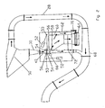
- FIG. 1 illustrates in principle an overall set-up of a sorting apparatus according to the invention. It is to be noted that the installation configuration of the individual components of this set-up may be altered depending on the requirements (product, space, etc.), for instance when using the "open channel” organization (see further below). As shown, in this configuration the overall length of the machine is about 17 meters.
- Item 20 is a feeding conveyor belt that feeds the articles. The providing of the articles proper as resulting from splitting, etcetera, of the tobacco has not been shown for clarity.
- the articles fall from the conveyor belt and into the transport system that in this embodiment centers on a substantially closed air-carrying duct arrangement To this effect, a feeding chute 21 opens towards the conveyor belt side, and particles will fall through this chute.
- the transporting air circulates through various openings in an inclined plate 23, although in principle, another gas or gas mixture could be used.
- the size and distribution of the openings and of other inlets, not shown in detail, would give an appropriate feeding speed for letting the articles or product travel independently from each other through the apparatus channel.
- the net air exchange through chute 21 should be kept low to maintain both dust loss and also maintain air intake at low levels. One way to effect this is keeping the local internal air pressure of the system approximately equal to ambient air pressure.
- a rising duct will carry the particle stream to an appropriate height, in this case some 5 meters; thereafter, the rising duct proceeds as a generally horizontal tube.
- the air duct is divided through an inclined and slowly slanting downwardly separation plate 33 that carries an air transmission pattern of holes. In this manner, part of the air stream can be diverted to bypass duct 28, while the particles of interest cannot pass through the holes. On the other hand, small and generally uninteresting particles such as dust can pass through these holes.
- This feature allows for adjusting the air speed below the separating plate. Air speed before the separating plate is in a range of 20-30 meters/second, while it is in the range of e.g. 10-20 meters/second in the area where the inspection takes place. Through a certain centrifugal force, the particles of interest are driven to the descending and subsequently, nearly vertical wall at indication 30, and generally tend to turn their broad area in a more or less horizontal direction to the right side in the Figure.
- Both the centrifugal force and the air outletting through the plate can contribute to orient conforming particles.
- the result should be a monolayer of well-oriented "good” particles, so that a large fraction thereof will be accepted.
- the effect on "bad” particles need not be considered, inasmuch as the optical survey discussed hereinafter would be able to pick them out as being non-conforming.
- the inventor has found that the above manner of orienting the particles is inexpensive, uncomplicated, and has a high success rate.
- the separation of unwanted particles is effected during the substantially vertical motion of the particles, through optical inspection and then removal to the right (or alternatively, to the left, or in other directions) in an inspection/separation duct 40, which operation will be more clearly illustrated in Figure 2 .
- the duct orientation, and therefore, the particle motion may have some deviation from vertical: it is contemplated that +/- 15° would often be acceptable, and in any way, +/-5° would give a good solution. More or less similar deviations from a straight-line motion could apply.
- the stream with particles retained and the bypass stream 28 of air merge again. Downstream from indication 32, the useful particles are removed from the system in an air-operated product separator arrangement 34 for further processing not considered here.
- air-product separator 34 goes through further ducts and main driving air pump arrangement 36. Finally, the overall duct is attached at indication 38 to the particle feeding position discussed earlier. Generally, there is little loss of air, and therefore also little air suppletion will be necessary, so that the process as a whole takes place in a substantially closed system: the air will cycle several times before being exhausted with the useful particles at air-product separator 34 or via the air bleed-off pipe which is connected to the circuit as a standard going to an exhaust air treatment device. This lowers overall noise levels, and also lowers the risk of high dust concentrations outside the system.
- the preferred embodiment as shown has the sorting during a falling motion of the particles, in principle other straight-line arrangements could operate in a satisfying manner.
- the primary motion is horizontal, the removal of non-conforming particle could be effected in a substantially horizontal, in a substantially vertical manner, or according to still other orientations.
- the primary motion is ascending or descending, various geometrical arrangements can be designed, also depending on the gas velocity, the size of the channel, the nature of the conforming and/or non-conforming particles, etcetera.
- Figure 2 illustrates an enlarged view of a part of sorting facility proper according to the invention, showing in particular items 28, 30 and 40 of Figure 1 .
- the downwardly inclined course at separation plate 50 (indicated with numeral 33 in figure 1 ), which lets the particles more or less “approach” the wall 30 at reduced air velocities in a range of 10 to 20 meters/second.
- the downward inclination of plate 50 shown in the figures is plane, said inclination preferably is cylindrically towards wall 30.
- the air flow through separation 50 would assist such "approach”.
- the transition between the part at 50 and the selection facility proper should be short to maintain the particle orientation; in the embodiment it is about 10% of the total system height, or some 35 centimeters.
- the vertical part of the duct 40 has a more or less square or rectangular cross-section.
- the selecting proper is effected with double-sided background illumination sources such as lighting 56, double sided narrow beam particle lighting 54, double mirrors 53 and double-sided line cameras 52.
- double-sided background illumination sources such as lighting 56, double sided narrow beam particle lighting 54, double mirrors 53 and double-sided line cameras 52.
- the output signals from the horizontal line of optical detection units such as cameras are processed in a processing facility not shown, which facility can measure particle shapes in appropriate manner, through correlating successive scans, measuring total exposed particle area, and rejecting such particles as considered non-conforming to the standard range of particle shapes.
- the available data processing time interval can be kept sufficiently long for a moderate-power computer.
- the particle proceeds downward in a vertical direction. If the particle is considered bad however, at indication 58 the particle will be removed by suction to the right. Through the suction by underpressure, no additional superfluous air motion and no unwanted turbulence will be introduced into the falling duct.
- the removal operation proper can be further effected or supported by a gas nozzle 66 that is momentarily activated for ejecting the particle through the opening at indication 58; this lets the non-conforming particle escape in a horizontal direction that is substantially across the primary motion of the particles before separation.
- the removal can have some tolerance from horizontal, such as +/- 15°.
- gravity and/or principal air movement will make the rejected particle fall downward.
- a perforated plate separates the reject duct that goes to reject bin 64, whereas the bulk of the air stream through underpressure by pump 70 will at indication 62 be led to another part of the closed system or elsewhere.
- said air stream might near indication 62 reenter bypass duct 28, and therefore remain as well in the overall system.
- the two principal streams 28,72 of air merge again. This merging can alternatively occur behind air-product separator facility 34, as in Fig. 1 .
- air-product separator facility 34 for clarity, no extensive discussion of air-product separator facility 34 is given, inasmuch as the removing of particles by air-product separator activity is well-known to persons skilled in the art of air-driving particles in an industrial environment.
- Figure 3 shows an article carrying channel wall 41 of duct 40 with extensions 42 to keep the articles from moving along the channel wall. It has been found that such will keep particle speed more uniform, so that the arrival of a particular particle at the position of nozzle 66 can be predicted more accurately. Indeed, the particles will not be delayed by extensive friction along the wall.
- the extensions will influence the boundary layer of the flowing gas and may look like fish scales. Their height (perpendicular to the wall) is in a range of 0.5 to 2.5 millimeters, whereas their area (along the duct's wall) is a few millimeters square. Mechanical working of the wall will allow easy manufacture thereof.
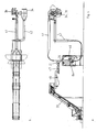
- Figure 4 shows an overall set-up of another sorting system according to the invention.
- the feeding conveyer 20 feeds the articles to a vibrating plate 46 that forms a uniform layer of the articles and the latter feeds the articles to a speedy tape transporter 47 that reduces the thickness of the layer of articles.
- the articles then are fed into the feeding chute 21 where below indication 30 the articles enter an inspection/separation duct 40 that is positioned within housing 86.
- duct 40 forms a part of a quasi-closed system comprising tubes 41,42 that connect the duct 40 to air-operated product separator arrangement 34 which is connected to air pump arrangement 36. In this case the articles are sucked into the duct 40 by an under-pressure that is created in tube 42.
- Figure 5 illustrates an enlarged view of a part of the system of figure 4 comprising duct 40 below point 30 and chute 21.
- the upper part of the duct 40 is here over a length of about 1 meter laterally bordered by a cover tube 84 which feeds though a throttle-valve 83 a leakage air flow into duct 40 at location 85, below which the inspection and separation of impurities and unwanted articles takes place in a further part of duct 40 having a length of e.g. about 0.5 meter.
- the effect of said leakage airflow is illustrated in figure 6 .
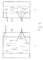
- Figure 6 shows two cross-sections of the part shown in figure 5 at different heights.
- the a and b figure 6 are taken respectively above point 85 and below point 85 in figure 5 .
- the particles 99 are present all over the cross-section of duct 40, their main orientation being parallel to wall 41 of duct 40.
- Below level 85 the leakage air flow is introduced into the duct 40, flows along the walls thereof and forms a compartment 49 in duct 40 with a smaller width, into which compartment the articles 99 are confined.
- This has several advantages. Firstly, the walls of duct 40 which contain transparent parts below level 85 are kept free from impurities that may hamper the inspection.
- the layer of particles 99 is provided with a more uniform velocity distribution, which is important to enable an accurate timing between the observance of a bad particle and the moment of its separation.
- the focusing into the particles 99 has become easier since the layer thickness of the stream of particles 99, which corresponds with the width of compartment 49 in figure 6b , is decreased.
- housing 86 below level 85 (see figure 5 once more) the inspection and separation of particles is performed in housing 86.
- the inspection takes place through two optical detection systems, in this example two camera's 52 that observe the reflected light from a particle in duct 40.
- Two radiation sources, here lamps 80 are used for each camera 52 that throw angled radiation, here light, beams on the particle stream in order to reduce a possible shadow effect, if any.
- gas nozzle 66 by which such particles are ejected into a side-chamber 91 of the duct 40 which is through tube 93 connected to a reject enclosure and a separate air pump, the latter both not shown in the drawing.
- Anti back-flow arrangement 92 which here involves a so-called snail-shell construction of underpressure facility 62, prevents ejected particles from reentering duct 40.
- chamber 91 can be advantageously provided with an over pressure valve - also not shown in the drawing - which contributes to the prevention of re-entrance of ejected particles to duct 40 in case of pressure fluctuations.
- the over pressure valve can be provided with a particle filter and can be used together with a pump connected to tube 93 or in stead of such a pump. In stead of an over pressure valve a ventilator may be connected to chamber 91.
- the overall apparatus could be based on an open channel organization. This will obviate the need for various gas input/output balancing configurations.
- conveyor belt 20 ( Figure 1 ) could immediately feed duct 30 in Figure 2 .
- lamps are used for the optical inspection, the use of one or more lasers is feasible as well.
- the arrangement could need only a gas suction facility at the downstream end of the inspection/sorting channel prior to indication 68 in Figure 2 . Obviously, this would produce a low-cost arrangement as compared with the embodiment of Figure 2 .
- the embodiments should be considered as being illustrative, and no restriction should be construed from those embodiments, other than as have been recited in the Claims.
- the unit of figure 5 could e.g. be used in the system of figure 1
- the bypass of figure 2 could be used in system of figure 4
- details of the unit of figure 2 could be used in the unit of figure 5 and vice versa.
Landscapes
- Life Sciences & Earth Sciences (AREA)
- Agronomy & Crop Science (AREA)
- Sorting Of Articles (AREA)
- Air Transport Of Granular Materials (AREA)
- Separation Of Gases By Adsorption (AREA)
Claims (10)
- Procédé pour trier un flux d'articles généralement plats et légers, de dimensions variées, en exécutant un examen optique et, lorsque ce faisant un article non conforme est découvert, en retirant celui-ci du flux, dans lequel ledit examen et ledit tri sont effectués au cours d'un déplacement sensiblement en ligne droite desdits articles, et l'enlèvement est effectué par un entraînement par un gaz, dans une direction sensiblement transversale audit déplacement en ligne droite,
caractérisé en ce que
ledit flux est entraîné par un gaz,
ledit examen est précédé d'une orientation desdits articles par une force centrifuge qui oriente lesdits articles vers une paroi inclinée, dans une transition vers ledit déplacement en ligne droite, ledit déplacement en ligne droite étant sensiblement vertical dans une direction de chute, et
ledit entraînement par un gaz dans une direction sensiblement transversale audit déplacement en ligne droite est effectué par aspiration due à une dépression. - Procédé selon la revendication 1, caractérisé en ce qu'il est spécifiquement dimensionné pour trier des produits de tabac tels que des feuilles ou des parties de celles-ci, ou des tiges.
- Appareil comprenant une installation de tri pour trier un flux d'articles généralement plats et légers de dimensions variées en utilisant une installation d'examen optique (52, 543, 54, 56) qui active une installation d'enlèvement (58, 66) pour, lorsqu'un article non conforme est découvert, retirer ce dernier du flux, dans lequel ladite installation d'examen (52, 53, 54, 56) et ladite installation d'enlèvement (58, 66) sont agencées pour opérer au cours d'un déplacement sensiblement en ligne droite desdits articles, et ladite installation d'enlèvement (58, 66) est agencée pour enlever des articles non conformes par un entraînement par un gaz dans une direction sensiblement transversale audit déplacement en ligne droite,
caractérisé en ce que
ledit flux d'articles est entraîné par un gaz,
ladite installation d'examen (52, 53, 54, 56) est précédée d'une installation d'orientation (26) pour orienter lesdits articles par une force centrifuge et/ou une force par aspiration d'air qui est adaptée à orienter lesdits articles en direction d'une paroi inclinée (33; 50) qui sert de transition vers ladite section de déplacement en ligne droite (40),
ledit appareil comprend un conduit (40) orienté sensiblement verticalement, auquel sont amenés lesdits articles et dans lequel ledit déplacement en ligne droite desdits articles s'effectue dans une direction de chute, et
ladite installation d'enlèvement (58, 66) comprend une installation à dépression de gaz (62) alimentée par ledit conduit (40) de transport des articles. - Appareil selon la revendication 3, caractérisé en ce qu'il est dimensionné spécifiquement pour trier des feuilles de tabac ou des parties de celles-ci.
- Appareil selon la revendication 3 ou 4, caractérisé en ce que ladite installation d'examen (52, 53, 54, 56) et ladite installation d'enlèvement (58, 66) sont agencées successivement dans la direction de chute desdits articles.
- Appareil selon la revendication 3, caractérisé en ce qu'il est basé sur un système de canaux sensiblement fermés pour déplacer lesdits articles.
- Appareil selon la revendication 6, caractérisé en ce que ladite installation d'enlèvement (58, 66) contient une enceinte de refus (64) et un conduit de recyclage de gaz qui se reconnecte audit système de canaux clos.
- Appareil selon la revendication 3, caractérisé en ce que ladite paroi inclinée (66; 50) est associée à une installation de transmission de gaz (28) qui recycle le gaz transmis vers un point (68) de confluence aval alimenté par une sortie qui transporte des articles utiles transmis à travers ledit appareil.
- Appareil selon la revendication 3, caractérisé en ce qu'un conduit (40) de transport d'articles pourvu desdites installations d'examen et de tri contient des extensions (42) prenant naissance sur la paroi, pour empêcher lesdits articles de se déplacer le long de la paroi (41) de la conduite.
- Appareil selon la revendication 3, caractérisé en ce que ledit conduit (40) de transport d'articles est pourvu de plus de moyens (83, 84) de circulation d'air, qui opèrent pour confiner lesdits articles dans un compartiment plus petit à l'intérieur dudit conduit (40).
Priority Applications (2)
| Application Number | Priority Date | Filing Date | Title |
|---|---|---|---|
| EP05808176A EP1838464B1 (fr) | 2004-11-01 | 2005-10-19 | Procede et appareil pour trier un courant d'articles legers plats emmenes par du gaz |
| PL05808176T PL1838464T3 (pl) | 2004-11-01 | 2005-10-19 | Sposób sortowania napędzanego gazem strumienia zasadniczo płaskich i lekkich przedmiotów |
Applications Claiming Priority (3)
| Application Number | Priority Date | Filing Date | Title |
|---|---|---|---|
| EP04105438 | 2004-11-01 | ||
| PCT/EP2005/055365 WO2006048376A1 (fr) | 2004-11-01 | 2005-10-19 | Procede et appareil pour trier un courant d'articles legers plats emmenes par du gaz |
| EP05808176A EP1838464B1 (fr) | 2004-11-01 | 2005-10-19 | Procede et appareil pour trier un courant d'articles legers plats emmenes par du gaz |
Publications (2)
| Publication Number | Publication Date |
|---|---|
| EP1838464A1 EP1838464A1 (fr) | 2007-10-03 |
| EP1838464B1 true EP1838464B1 (fr) | 2009-07-08 |
Family
ID=35590236
Family Applications (1)
| Application Number | Title | Priority Date | Filing Date |
|---|---|---|---|
| EP05808176A Expired - Lifetime EP1838464B1 (fr) | 2004-11-01 | 2005-10-19 | Procede et appareil pour trier un courant d'articles legers plats emmenes par du gaz |
Country Status (8)
| Country | Link |
|---|---|
| US (1) | US8002117B2 (fr) |
| EP (1) | EP1838464B1 (fr) |
| JP (1) | JP5455306B2 (fr) |
| CN (1) | CN101132867B (fr) |
| AT (1) | ATE435710T1 (fr) |
| DE (1) | DE602005015360D1 (fr) |
| PL (1) | PL1838464T3 (fr) |
| WO (1) | WO2006048376A1 (fr) |
Cited By (3)
| Publication number | Priority date | Publication date | Assignee | Title |
|---|---|---|---|---|
| WO2011083070A2 (fr) | 2010-01-07 | 2011-07-14 | Hauni Maschinenbau Ag | Procédé et dispositif pour séparer des corps étrangers d'un flux de tabac |
| US8002117B2 (en) | 2004-11-01 | 2011-08-23 | Comas, S.P.A. | Method and apparatus for sorting a gas-driven stream of generally flat and lightweight articles |
| EP3492186A1 (fr) | 2017-12-04 | 2019-06-05 | Hauni Maschinenbau GmbH | Trieuse dans l'industrie du tabac et procédé de tri d'articles sensiblement plats et légers |
Families Citing this family (8)
| Publication number | Priority date | Publication date | Assignee | Title |
|---|---|---|---|---|
| US8281931B2 (en) * | 2009-09-18 | 2012-10-09 | Key Technology, Inc. | Apparatus and method for post-threshing inspection and sorting of tobacco lamina |
| CN102029263A (zh) * | 2010-11-19 | 2011-04-27 | 南京文采科技有限责任公司 | 叶中含梗检测与剔除装置 |
| CN102551188B (zh) * | 2011-12-31 | 2014-04-02 | 贵州烟叶复烤有限责任公司 | 烟叶梗头打叶处理工艺 |
| WO2015113769A1 (fr) * | 2014-01-31 | 2015-08-06 | Thyssenkrupp Industrial Solutions Ag | Séparateur à dérivation |
| CN104117489A (zh) * | 2014-07-09 | 2014-10-29 | 成都信泰科技有限公司 | 气流式光谱异物剔除方法及设备 |
| JP6275911B1 (ja) | 2017-10-02 | 2018-02-07 | 株式会社服部製作所 | 色彩選別機 |
| WO2022102135A1 (fr) * | 2020-11-16 | 2022-05-19 | 株式会社Fuji | Système d'élimination de matières étrangères |
| CN114542724B (zh) * | 2022-02-24 | 2026-04-21 | 株式会社Bfc | 电控空压阀及高速微小零部件的电控空压阀选取装置 |
Family Cites Families (23)
| Publication number | Priority date | Publication date | Assignee | Title |
|---|---|---|---|---|
| GB1397726A (en) * | 1971-07-28 | 1975-06-18 | Molins Ltd | Tobacco feed systems |
| US3968366A (en) * | 1972-03-16 | 1976-07-06 | Asfour Emil S | Apparatus for sorting tobacco leaves |
| DE3227670A1 (de) * | 1981-07-24 | 1983-02-10 | Molins PLC, London | Verfahren und vorrichtung zum pneumatischen zufuehren von tabak |
| DE3428966A1 (de) * | 1984-08-06 | 1986-02-06 | Institut po Techničeska Kibernetika i Robotika, Sofia/Sofija | Verfahren und vorrichtung zum sortieren von tabakblaettern |
| US4657144A (en) * | 1985-02-25 | 1987-04-14 | Philip Morris Incorporated | Method and apparatus for detecting and removing foreign material from a stream of particulate matter |
| US4915824A (en) * | 1985-08-12 | 1990-04-10 | Surtees Guy F | Pneumatic classifier for tobacco and method |
| GB8625953D0 (en) * | 1986-10-30 | 1986-12-03 | G B E International Plc | Programmable zone size in detection system |
| JPS63152418A (ja) * | 1986-12-15 | 1988-06-24 | Tatsumi Eyaa Eng:Kk | 原綿中の色物検出装置における空気回路 |
| US5325875A (en) * | 1987-08-24 | 1994-07-05 | Universal Leaf Tobacco Co., Inc. | Apparatus for separating threshed leaf tobacco |
| US4895174A (en) * | 1988-05-19 | 1990-01-23 | R. J. Reynolds Tobacco Company | Tobacco particle separator |
| DE4206054C2 (de) * | 1991-03-06 | 2002-11-28 | Hauni Werke Koerber & Co Kg | Verfahren und Vorrichtung zum Herstellen eines Tabakstranges |
| US5305893A (en) * | 1991-09-30 | 1994-04-26 | Brown & Williamson Tobacco Corporation | Conveyor system including flow diverter means |
| JPH0623219A (ja) * | 1992-07-10 | 1994-02-01 | Mitsubishi Heavy Ind Ltd | 集塵装置 |
| JP2848776B2 (ja) * | 1994-01-06 | 1999-01-20 | 鐘紡株式会社 | 供給装置 |
| DE19516569B4 (de) * | 1995-05-05 | 2009-04-23 | TRüTZSCHLER GMBH & CO. KG | Vorrichtung zum Abscheiden von Fremdstoffen, z. B. metallischer Verunreinigungen, aus einer Fasertransportstrecke in der Spinnereivorbereitung |
| US5862919A (en) * | 1996-10-10 | 1999-01-26 | Src Vision, Inc. | High throughput sorting system |
| US20020175113A1 (en) * | 1998-05-22 | 2002-11-28 | Hannu Tahkanen | Method and apparatus for sorting of chips |
| IT1316762B1 (it) * | 1999-03-11 | 2003-05-12 | Hauni Maschinenbau Ag | Dispositivo per scompattare e rendere uniforme una corrente di tabacco addotta in continuo |
| US6374998B1 (en) * | 1999-04-29 | 2002-04-23 | Advanced Sorting Technologies Llc | “Acceleration conveyor” |
| DE19948559C1 (de) * | 1999-10-08 | 2001-02-01 | Bat Cigarettenfab Gmbh | Verfahren zur Erfassung der Partikel eines Tabakpartikel-Stroms |
| US6371126B1 (en) * | 2000-03-03 | 2002-04-16 | Brown & Williamson Tobacco Corporation | Tobacco recovery system |
| CA2499853C (fr) * | 2004-03-15 | 2012-11-13 | Universal Leaf Tobacco Company, Inc. | Appareil et methode de balayage et de tri de feuilles de tabac |
| WO2006048376A1 (fr) | 2004-11-01 | 2006-05-11 | Machinefabriek Van Hoek B.V. | Procede et appareil pour trier un courant d'articles legers plats emmenes par du gaz |
-
2005
- 2005-10-19 WO PCT/EP2005/055365 patent/WO2006048376A1/fr not_active Ceased
- 2005-10-19 EP EP05808176A patent/EP1838464B1/fr not_active Expired - Lifetime
- 2005-10-19 DE DE602005015360T patent/DE602005015360D1/de not_active Expired - Lifetime
- 2005-10-19 AT AT05808176T patent/ATE435710T1/de not_active IP Right Cessation
- 2005-10-19 PL PL05808176T patent/PL1838464T3/pl unknown
- 2005-10-19 JP JP2007538388A patent/JP5455306B2/ja not_active Expired - Fee Related
- 2005-10-19 CN CN2005800369195A patent/CN101132867B/zh not_active Expired - Fee Related
- 2005-10-19 US US11/666,393 patent/US8002117B2/en not_active Expired - Fee Related
Cited By (4)
| Publication number | Priority date | Publication date | Assignee | Title |
|---|---|---|---|---|
| US8002117B2 (en) | 2004-11-01 | 2011-08-23 | Comas, S.P.A. | Method and apparatus for sorting a gas-driven stream of generally flat and lightweight articles |
| WO2011083070A2 (fr) | 2010-01-07 | 2011-07-14 | Hauni Maschinenbau Ag | Procédé et dispositif pour séparer des corps étrangers d'un flux de tabac |
| WO2011083070A3 (fr) * | 2010-01-07 | 2011-09-09 | Hauni Maschinenbau Ag | Procédé et dispositif pour séparer des corps étrangers d'un flux de tabac |
| EP3492186A1 (fr) | 2017-12-04 | 2019-06-05 | Hauni Maschinenbau GmbH | Trieuse dans l'industrie du tabac et procédé de tri d'articles sensiblement plats et légers |
Also Published As
| Publication number | Publication date |
|---|---|
| US20080087583A1 (en) | 2008-04-17 |
| ATE435710T1 (de) | 2009-07-15 |
| WO2006048376A1 (fr) | 2006-05-11 |
| CN101132867B (zh) | 2012-06-13 |
| JP5455306B2 (ja) | 2014-03-26 |
| EP1838464A1 (fr) | 2007-10-03 |
| JP2008517752A (ja) | 2008-05-29 |
| PL1838464T3 (pl) | 2009-10-30 |
| DE602005015360D1 (de) | 2009-08-20 |
| US8002117B2 (en) | 2011-08-23 |
| CN101132867A (zh) | 2008-02-27 |
Similar Documents
| Publication | Publication Date | Title |
|---|---|---|
| JP3272606B2 (ja) | ガラスカレット分別装置 | |
| US6265683B1 (en) | Semiconductor material classification device | |
| JP5846348B2 (ja) | 光学式選別機 | |
| US4609108A (en) | Tobacco sorting method and apparatus | |
| US20230119149A1 (en) | Method and apparatus for sorting heterogeneous material | |
| US6003681A (en) | Off-belt stabilizing system for light-weight articles | |
| US5297667A (en) | System for stabilizing articles on conveyors | |
| CN102481599B (zh) | 用于烟草叶片的打叶后检验及分选的设备及方法 | |
| US3738484A (en) | Sorting machine | |
| US8002117B2 (en) | Method and apparatus for sorting a gas-driven stream of generally flat and lightweight articles | |
| US11033937B2 (en) | Color sorting machine | |
| KR20170137736A (ko) | 궤도 추적 센서 네트워크를 구비한 새로운 지능형 선별기 및 그 방법 | |
| EP1743713B1 (fr) | Dispostitif de tri par soufflage | |
| EP4063031A1 (fr) | Trieuse optique | |
| US3750881A (en) | Color sorter | |
| KR940009663A (ko) | 부품검사장치 및 그 장치를 사용한 검사방법 | |
| CN104998833A (zh) | 基于图像处理的透明矿质原料的浸水分选方法 | |
| JP2815633B2 (ja) | 米粒品位判別装置 | |
| EP3492186A1 (fr) | Trieuse dans l'industrie du tabac et procédé de tri d'articles sensiblement plats et légers | |
| JP2001038305A (ja) | 粒状体搬送装置及び粒状体群の外観検査装置 | |
| JP3180841B2 (ja) | 米粒品位判別装置 | |
| TR2025014266U5 (tr) | Ayıklama Makinesi | |
| WO2025238181A1 (fr) | Système et processus de tri de matières | |
| JPS602115B2 (ja) | 色彩選別機 |
Legal Events
| Date | Code | Title | Description |
|---|---|---|---|
| PUAI | Public reference made under article 153(3) epc to a published international application that has entered the european phase |
Free format text: ORIGINAL CODE: 0009012 |
|
| 17P | Request for examination filed |
Effective date: 20070426 |
|
| AK | Designated contracting states |
Kind code of ref document: A1 Designated state(s): AT BE BG CH CY CZ DE DK EE ES FI FR GB GR HU IE IS IT LI LT LU LV MC NL PL PT RO SE SI SK TR |
|
| 17Q | First examination report despatched |
Effective date: 20071116 |
|
| DAX | Request for extension of the european patent (deleted) | ||
| RAP1 | Party data changed (applicant data changed or rights of an application transferred) |
Owner name: COMAS S.P.A. |
|
| GRAP | Despatch of communication of intention to grant a patent |
Free format text: ORIGINAL CODE: EPIDOSNIGR1 |
|
| GRAS | Grant fee paid |
Free format text: ORIGINAL CODE: EPIDOSNIGR3 |
|
| GRAA | (expected) grant |
Free format text: ORIGINAL CODE: 0009210 |
|
| AK | Designated contracting states |
Kind code of ref document: B1 Designated state(s): AT BE BG CH CY CZ DE DK EE ES FI FR GB GR HU IE IS IT LI LT LU LV MC NL PL PT RO SE SI SK TR |
|
| REG | Reference to a national code |
Ref country code: GB Ref legal event code: FG4D |
|
| REG | Reference to a national code |
Ref country code: CH Ref legal event code: EP |
|
| REG | Reference to a national code |
Ref country code: IE Ref legal event code: FG4D |
|
| REF | Corresponds to: |
Ref document number: 602005015360 Country of ref document: DE Date of ref document: 20090820 Kind code of ref document: P |
|
| REG | Reference to a national code |
Ref country code: PL Ref legal event code: T3 |
|
| PG25 | Lapsed in a contracting state [announced via postgrant information from national office to epo] |
Ref country code: SI Free format text: LAPSE BECAUSE OF FAILURE TO SUBMIT A TRANSLATION OF THE DESCRIPTION OR TO PAY THE FEE WITHIN THE PRESCRIBED TIME-LIMIT Effective date: 20090708 |
|
| REG | Reference to a national code |
Ref country code: HU Ref legal event code: AG4A Ref document number: E006311 Country of ref document: HU |
|
| PG25 | Lapsed in a contracting state [announced via postgrant information from national office to epo] |
Ref country code: ES Free format text: LAPSE BECAUSE OF FAILURE TO SUBMIT A TRANSLATION OF THE DESCRIPTION OR TO PAY THE FEE WITHIN THE PRESCRIBED TIME-LIMIT Effective date: 20091019 Ref country code: FI Free format text: LAPSE BECAUSE OF FAILURE TO SUBMIT A TRANSLATION OF THE DESCRIPTION OR TO PAY THE FEE WITHIN THE PRESCRIBED TIME-LIMIT Effective date: 20090708 Ref country code: LT Free format text: LAPSE BECAUSE OF FAILURE TO SUBMIT A TRANSLATION OF THE DESCRIPTION OR TO PAY THE FEE WITHIN THE PRESCRIBED TIME-LIMIT Effective date: 20090708 Ref country code: AT Free format text: LAPSE BECAUSE OF FAILURE TO SUBMIT A TRANSLATION OF THE DESCRIPTION OR TO PAY THE FEE WITHIN THE PRESCRIBED TIME-LIMIT Effective date: 20090708 Ref country code: IS Free format text: LAPSE BECAUSE OF FAILURE TO SUBMIT A TRANSLATION OF THE DESCRIPTION OR TO PAY THE FEE WITHIN THE PRESCRIBED TIME-LIMIT Effective date: 20091108 |
|
| PG25 | Lapsed in a contracting state [announced via postgrant information from national office to epo] |
Ref country code: LV Free format text: LAPSE BECAUSE OF FAILURE TO SUBMIT A TRANSLATION OF THE DESCRIPTION OR TO PAY THE FEE WITHIN THE PRESCRIBED TIME-LIMIT Effective date: 20090708 |
|
| PG25 | Lapsed in a contracting state [announced via postgrant information from national office to epo] |
Ref country code: PT Free format text: LAPSE BECAUSE OF FAILURE TO SUBMIT A TRANSLATION OF THE DESCRIPTION OR TO PAY THE FEE WITHIN THE PRESCRIBED TIME-LIMIT Effective date: 20091109 Ref country code: BG Free format text: LAPSE BECAUSE OF FAILURE TO SUBMIT A TRANSLATION OF THE DESCRIPTION OR TO PAY THE FEE WITHIN THE PRESCRIBED TIME-LIMIT Effective date: 20091008 |
|
| PG25 | Lapsed in a contracting state [announced via postgrant information from national office to epo] |
Ref country code: EE Free format text: LAPSE BECAUSE OF FAILURE TO SUBMIT A TRANSLATION OF THE DESCRIPTION OR TO PAY THE FEE WITHIN THE PRESCRIBED TIME-LIMIT Effective date: 20090708 Ref country code: DK Free format text: LAPSE BECAUSE OF FAILURE TO SUBMIT A TRANSLATION OF THE DESCRIPTION OR TO PAY THE FEE WITHIN THE PRESCRIBED TIME-LIMIT Effective date: 20090708 Ref country code: CZ Free format text: LAPSE BECAUSE OF FAILURE TO SUBMIT A TRANSLATION OF THE DESCRIPTION OR TO PAY THE FEE WITHIN THE PRESCRIBED TIME-LIMIT Effective date: 20090708 Ref country code: RO Free format text: LAPSE BECAUSE OF FAILURE TO SUBMIT A TRANSLATION OF THE DESCRIPTION OR TO PAY THE FEE WITHIN THE PRESCRIBED TIME-LIMIT Effective date: 20090708 |
|
| PLBE | No opposition filed within time limit |
Free format text: ORIGINAL CODE: 0009261 |
|
| STAA | Information on the status of an ep patent application or granted ep patent |
Free format text: STATUS: NO OPPOSITION FILED WITHIN TIME LIMIT |
|
| PG25 | Lapsed in a contracting state [announced via postgrant information from national office to epo] |
Ref country code: MC Free format text: LAPSE BECAUSE OF NON-PAYMENT OF DUE FEES Effective date: 20091031 Ref country code: SK Free format text: LAPSE BECAUSE OF FAILURE TO SUBMIT A TRANSLATION OF THE DESCRIPTION OR TO PAY THE FEE WITHIN THE PRESCRIBED TIME-LIMIT Effective date: 20090708 |
|
| REG | Reference to a national code |
Ref country code: CH Ref legal event code: PL |
|
| 26N | No opposition filed |
Effective date: 20100409 |
|
| REG | Reference to a national code |
Ref country code: FR Ref legal event code: ST Effective date: 20100630 |
|
| PG25 | Lapsed in a contracting state [announced via postgrant information from national office to epo] |
Ref country code: FR Free format text: LAPSE BECAUSE OF NON-PAYMENT OF DUE FEES Effective date: 20091102 |
|
| PG25 | Lapsed in a contracting state [announced via postgrant information from national office to epo] |
Ref country code: GR Free format text: LAPSE BECAUSE OF FAILURE TO SUBMIT A TRANSLATION OF THE DESCRIPTION OR TO PAY THE FEE WITHIN THE PRESCRIBED TIME-LIMIT Effective date: 20091009 Ref country code: LI Free format text: LAPSE BECAUSE OF NON-PAYMENT OF DUE FEES Effective date: 20091031 Ref country code: IE Free format text: LAPSE BECAUSE OF NON-PAYMENT OF DUE FEES Effective date: 20091019 Ref country code: CH Free format text: LAPSE BECAUSE OF NON-PAYMENT OF DUE FEES Effective date: 20091031 |
|
| PG25 | Lapsed in a contracting state [announced via postgrant information from national office to epo] |
Ref country code: LU Free format text: LAPSE BECAUSE OF NON-PAYMENT OF DUE FEES Effective date: 20091019 |
|
| PG25 | Lapsed in a contracting state [announced via postgrant information from national office to epo] |
Ref country code: CY Free format text: LAPSE BECAUSE OF FAILURE TO SUBMIT A TRANSLATION OF THE DESCRIPTION OR TO PAY THE FEE WITHIN THE PRESCRIBED TIME-LIMIT Effective date: 20090708 |
|
| PG25 | Lapsed in a contracting state [announced via postgrant information from national office to epo] |
Ref country code: SE Free format text: LAPSE BECAUSE OF FAILURE TO SUBMIT A TRANSLATION OF THE DESCRIPTION OR TO PAY THE FEE WITHIN THE PRESCRIBED TIME-LIMIT Effective date: 20090708 |
|
| PGFP | Annual fee paid to national office [announced via postgrant information from national office to epo] |
Ref country code: PL Payment date: 20130917 Year of fee payment: 9 |
|
| PGFP | Annual fee paid to national office [announced via postgrant information from national office to epo] |
Ref country code: BE Payment date: 20131025 Year of fee payment: 9 |
|
| PGFP | Annual fee paid to national office [announced via postgrant information from national office to epo] |
Ref country code: NL Payment date: 20131028 Year of fee payment: 9 Ref country code: IT Payment date: 20131022 Year of fee payment: 9 Ref country code: TR Payment date: 20131011 Year of fee payment: 9 |
|
| REG | Reference to a national code |
Ref country code: NL Ref legal event code: V1 Effective date: 20150501 |
|
| PG25 | Lapsed in a contracting state [announced via postgrant information from national office to epo] |
Ref country code: BE Free format text: LAPSE BECAUSE OF NON-PAYMENT OF DUE FEES Effective date: 20141031 |
|
| PG25 | Lapsed in a contracting state [announced via postgrant information from national office to epo] |
Ref country code: HU Free format text: LAPSE BECAUSE OF NON-PAYMENT OF DUE FEES Effective date: 20141020 Ref country code: NL Free format text: LAPSE BECAUSE OF NON-PAYMENT OF DUE FEES Effective date: 20150501 Ref country code: IT Free format text: LAPSE BECAUSE OF NON-PAYMENT OF DUE FEES Effective date: 20141019 |
|
| PGRI | Patent reinstated in contracting state [announced from national office to epo] |
Ref country code: HU Effective date: 20150609 |
|
| PGFP | Annual fee paid to national office [announced via postgrant information from national office to epo] |
Ref country code: DE Payment date: 20151029 Year of fee payment: 11 Ref country code: GB Payment date: 20151022 Year of fee payment: 11 |
|
| PG25 | Lapsed in a contracting state [announced via postgrant information from national office to epo] |
Ref country code: PL Free format text: LAPSE BECAUSE OF NON-PAYMENT OF DUE FEES Effective date: 20141019 |
|
| PGFP | Annual fee paid to national office [announced via postgrant information from national office to epo] |
Ref country code: HU Payment date: 20151006 Year of fee payment: 11 |
|
| REG | Reference to a national code |
Ref country code: DE Ref legal event code: R119 Ref document number: 602005015360 Country of ref document: DE |
|
| GBPC | Gb: european patent ceased through non-payment of renewal fee |
Effective date: 20161019 |
|
| PG25 | Lapsed in a contracting state [announced via postgrant information from national office to epo] |
Ref country code: DE Free format text: LAPSE BECAUSE OF NON-PAYMENT OF DUE FEES Effective date: 20170503 Ref country code: GB Free format text: LAPSE BECAUSE OF NON-PAYMENT OF DUE FEES Effective date: 20161019 |
|
| PG25 | Lapsed in a contracting state [announced via postgrant information from national office to epo] |
Ref country code: HU Free format text: LAPSE BECAUSE OF NON-PAYMENT OF DUE FEES Effective date: 20151021 Ref country code: TR Free format text: LAPSE BECAUSE OF NON-PAYMENT OF DUE FEES Effective date: 20141019 |