EP1838566B1 - Procede et appareil de commande de direction - Google Patents
Procede et appareil de commande de direction Download PDFInfo
- Publication number
- EP1838566B1 EP1838566B1 EP05812061.9A EP05812061A EP1838566B1 EP 1838566 B1 EP1838566 B1 EP 1838566B1 EP 05812061 A EP05812061 A EP 05812061A EP 1838566 B1 EP1838566 B1 EP 1838566B1
- Authority
- EP
- European Patent Office
- Prior art keywords
- steering
- vehicle
- reaction force
- steering wheel
- road surface
- Prior art date
- Legal status (The legal status is an assumption and is not a legal conclusion. Google has not performed a legal analysis and makes no representation as to the accuracy of the status listed.)
- Ceased
Links
Images


Classifications
-
- B—PERFORMING OPERATIONS; TRANSPORTING
- B62—LAND VEHICLES FOR TRAVELLING OTHERWISE THAN ON RAILS
- B62D—MOTOR VEHICLES; TRAILERS
- B62D6/00—Arrangements for automatically controlling steering depending on driving conditions sensed and responded to, e.g. control circuits
- B62D6/008—Control of feed-back to the steering input member, e.g. simulating road feel in steer-by-wire applications
-
- B—PERFORMING OPERATIONS; TRANSPORTING
- B62—LAND VEHICLES FOR TRAVELLING OTHERWISE THAN ON RAILS
- B62D—MOTOR VEHICLES; TRAILERS
- B62D5/00—Power-assisted or power-driven steering
- B62D5/001—Mechanical components or aspects of steer-by-wire systems, not otherwise provided for in this maingroup
- B62D5/005—Mechanical components or aspects of steer-by-wire systems, not otherwise provided for in this maingroup means for generating torque on steering wheel or input member, e.g. feedback
- B62D5/006—Mechanical components or aspects of steer-by-wire systems, not otherwise provided for in this maingroup means for generating torque on steering wheel or input member, e.g. feedback power actuated
-
- B—PERFORMING OPERATIONS; TRANSPORTING
- B62—LAND VEHICLES FOR TRAVELLING OTHERWISE THAN ON RAILS
- B62D—MOTOR VEHICLES; TRAILERS
- B62D5/00—Power-assisted or power-driven steering
- B62D5/04—Power-assisted or power-driven steering electrical, e.g. using an electric servo-motor connected to, or forming part of, the steering gear
- B62D5/0457—Power-assisted or power-driven steering electrical, e.g. using an electric servo-motor connected to, or forming part of, the steering gear characterised by control features of the drive means as such
- B62D5/046—Controlling the motor
- B62D5/0466—Controlling the motor for returning the steering wheel to neutral position
Definitions
- the present invention relates to the field of steering control for vehicles and in particular to electronic steering control systems.
- the steering reaction force correction proportional to the detected road surface reaction force is computed and added to the steering reaction force, so that the condition of the road surface is transmitted to the driver.
- a steering force (T) applied to the steering column (steering shaft) is computed.
- a control value (aT) (where a is the coefficient corresponding to the steering force gear ratio) for rotating the steering shaft in the direction of applied steering force (T) is also computed.
- the road surface reaction force from the steering reaction force sensor is transmitted to the steering reaction force, for example, when the vehicle turns an L-shaped corner, so that quick return steering is required. If the tire dips due to the rough road surface (holes, etc.), due to the signal from the steering reaction force sensor, quick maneuvering of the steering wheel may be hindered, which is undesirable (see Figure 7 ). If the embodiment of the present invention is not applied, this occurs because the steering reaction force is added to track the kickback from the road surface, the steering force rises abruptly, and it becomes difficult for the driver to respond quickly.
- Document WO 2004/101346 A1 discloses a steering control device wherein a steering shaft reaction torque is estimated by steering shaft reaction torque-estimating means and reference road surface reaction torque is estimated by reference road surface reaction torque-estimating means. The obtained steering shaft reaction torque and reference road surface reaction torque are weighted. Based on the weighted result, aimed steering reaction torque is set by aimed steering reaction torque-producing means. The width and inclination of a hysteresis of the aimed steering reaction torque are each adjusted so that steering feeling is improved.
- the object underlying the present invention is achieved by a steering control device according to independent claim 1, by a vehicle according to independent claim 2, and by a method for controlling steering in a vehicle according to independent claim 11.
- Preferred embodiments are defined in the respective dependent claims.
- a steering control device for use in a vehicle having a steering wheel that receives steering input, and an electronically-controlled steering unit that turns the vehicle's wheels over a road surface based on the position of the steering wheel.
- the steering control device includes a reaction force device coupled to the steering wheel and responsive to a control signal to apply a steering reaction force to the steering wheel; and a controller adapted to generate the control signal in response to the movement of the steering wheel and the road surface reaction force.
- the controller varies the control signal to increase the steering reaction force in response to the road surface reaction force when the steering wheel is turning and to decrease the reaction force in response to the road surface force when the steering wheel is returning.
- a method for controlling steering in a vehicle having a steering wheel and a reaction device to impose a steering reaction force onto the steering wheel in response to a steering force control signal includes calculating the steering force control signal based on a road surface reaction. force and a gain; determining whether the steering wheel is in a turning or returning mode; and setting the gain at a higher value when the steering wheel is in a turning mode.
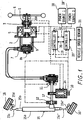
- FIG 1 is an overall system diagram illustrating the vehicle steering device of the first embodiment.
- Figures 2 a-c are detailed diagrams illustrating the clutch, cable column, and torque sensor components, respectively, in the vehicle steering device of the first embodiment.
- the vehicle steering device is composed of a reaction force device, an auxiliary device, an electronically-controlled steering device, and a controller.
- the reaction force device has steering angle sensor 1, encoder 2, torque sensors 3, and reaction force motor 5.
- the steering angle sensor 1 is a means for detecting the angular position of steering wheel 6. It is set on a column shaft 8a that connects a cable column 7 and a steering wheel 6. That is, steering angle sensor 1 is placed between steering wheel 6 and torque sensors 3 and is unaffected by the change in angle due to the twisting of torque sensors 3 so that the sensor 1 can detect the steering angle.
- an absolute type resolver (not shown) or the like is used.
- the torque sensors 3 form a double system and are arranged between the steering angle sensor 1 and reaction force motor 5.
- the system is made up of two torque sensors, that is, torque sensor 3 and torque sensor 12.
- Figure 2C is a diagram illustrating in detail a torque sensor unit.
- Each torque sensor 3 has a torsion bar extending in the axial direction, a first shaft connected to one end of the torsion bar and coaxial to the torsion bar, a second shaft connected to the other end of the torsion bar and is coaxial to the torsion bar and the first shaft, a first magnetic body fixed to the first shaft, a second magnetic body fixed to the second shaft, a coil facing the first magnetic body and the second magnetic body, and a third magnetic body that forms a magnetic circuit together with the first magnetic body and second magnetic body.
- the coil detects the torque from the output signal on the basis of the inductance that changes corresponding to the relative displacement between the first magnetic body and the second magnetic body on the basis of the twisting of the torsion bar.
- the reaction force motor 5 is a reaction force actuator that imparts a reaction force to the steering wheel 6.
- the reaction force motor 5 is made of a 1-rotor/1-stator type of electric motor with the column shaft 8a as the rotary shaft.
- the housing is fixed at an appropriate location on the vehicle body.
- a brushless motor is used as the reaction force motor 5 with the encoder 2 and a Hall IC (not shown in the figure), which are required for use with a brushless motor. If only a Hall IC is used, although it will be possible to drive the motor that generates the motor torque, nevertheless there will be small variations in the output torque, and the feel of the steering reaction force will be poor.
- encoder 2 is placed on the shaft of column shaft 8a to control the motor. As a result, the small torque variations can be reduced, and the steering reaction force feel is improved.
- a resolver can be used in place of encoder 2.
- the auxiliary unit is composed of cable column 7 and clutch 9.
- the clutch 9 is arranged between column shaft 8a and pulley shaft 8b.
- An electromagnetic clutch is used in the first embodiment.
- Figure 2A is a diagram illustrating in detail the clutch component 9.
- clutch 9 When power is turned on to the electromagnetic clutch, clutch 9 generates magnetic flux ⁇ .
- the armature is magnetically drawn to the brushes of the rotor against the restoring force of a leaf spring
- column shaft 8a, the input shaft, and pulley shaft 8b, the output shaft, are connected to each other.
- steering wheel 6 is rotated, its rotational force is transmitted via clutch 9 to the pulley of cable column 7 to rotate the pulley of cable column 7.
- the rotational force is transmitted via clutch 9 to steering wheel 6.
- the transmission torque capacity of clutch 9 can be set as desired by changing the drawing force as magnetic flux ⁇ generated by the magnetic coil is changed. Also, a scheme in which the clutch is released when the power is turned on may also be used.
- the cable column 7 has a mechanical backup mechanism that can play the part of the column shaft in transmitting the torque while it detours to avoid interference with the element included between the reaction force device and the steering device.
- Figure 2B is a diagram illustrating in detail the cable column unit. In the structure of cable column 7, two interior cables, each end of which is fixed to a reel 22, are wound onto the two reels 22, and the two ends of the exterior sheath in which two inner cables are inserted are fixed to two reel housings.
- the steering unit includes encoder 10, steering angle sensor 11, torque sensors 12, steering motors 14, steering unit (steered wheel turning unit) 15, and steered wheels 16, 16'.
- the steering angle sensor 11 and torque sensors 12 are mounted on pinion shaft 17, on one end of which the pulley of cable column 7 is attached, and on the other end of which a pinion gear is formed.
- a steering angle sensor 11 an absolute type resolver or the like, which detects the rotational velocity of the shaft can be used.
- torque sensors 3, and torque sensors 12 form a double system that detects torque from changes in inductance.
- Steering angle sensor 11 is set on the side of cable column 7, and torque sensors 12 are set on the side of steering unit 15. As a result, when the steering angle is detected by steering angle sensor 11, it is unaffected by the change in the angle due to the twisting of torque sensors 12.
- the steering motors 14 have a structure in which a pinion gear engaged to the worm gear set at the central position between steering angle sensor 11 of the pinion shaft 17 and torque sensors 12 is set on the motor shaft, so that a steering torque is applied to pinion shaft 17 when the motor is on.
- the steering motors 14 form a double system with a 1-rotor/2-stator structure.
- the steering motors 14 are brushless motors that form first and second steering motors 14.
- encoder 10 and a Hall IC (not shown in the figure) are used.
- the steering unit 15 has a structure in which left/right steered road wheels 16, 16' turn as pinion shaft 17 rotates. It has rack shaft 15b that forms a rack gear engaged with the pinion gear of pinion shaft 17 and inserted in rack tube 15a, tie rods 15c, 15c' fixed to the two ends of rack shaft 15b extending in the left/right direction of the vehicle, and knuckle arms 15d, 15d' having one end fixed to the tie rods 15c, 15c' and the other end fixed to the steered road wheels 16, 16'.
- the controller has a double system design composed of two power sources 18, 18' and two controllers 19, 19' that perform processing and arithmetic operations.
- the controllers 19, 19' receive the detected signals from the following parts: steering angle sensor 1, encoder 2, torque sensors 3, and the Hall IC of the reaction force device, as well as encoder 10, steering angle sensor 11, torque sensors 12, Hall IC, and vehicle speed sensor 21 (vehicle speed detection means) of the steering device.
- controller 19 sets the control quantities of reaction force motor 5 and steering motor 14, and controls and drives each of steering motors 14. Also, during ordinary system conditions, controller 19 releases the clutch 9. Otherwise, the system engages clutch 9 to establish a mechanical connection between steering wheel 6 and the steered road wheels 16, 16'.
- Th Kp ⁇ ⁇ + Gf ⁇ F
- (Kp) represents the steering angle feedback gain
- ⁇ represents the steering angle
- (Gf) represents the road surface reaction force feedback gain
- (F) represents the road surface reaction force.
- the first term on the right-hand side sets the control value of the steering reaction force on the basis of steering angle ⁇
- the second term on the right-hand side sets the control value on the basis of road surface reaction force (F), so that it can reflect the influence on the steering reaction force of the force on the tires from the road surface on the tires.
- road surface reaction force feedback gain changes as a function of the steering state. Its value is set such that in the case of turning the steering wheel, the road surface feel is transmitted to the driver through an appropriate steering reaction force.
- the amount of feedback of the road surface reaction force component is set smaller so that during the steering wheel return operation, the steering wheel is not hindered by excessive shock forces, etc.
- the (Low), (High) are determined on the basis of the graph to be explained below ( Figure 4 ). However, they may also be preset constants.
- Kd and Kdd are preset constants.
- Figure 3 is a flow chart illustrating the method for setting road surface reaction force feedback gain (Gf). Each step will be explained below.
- step S1 the signal from steering angle sensor 1 is read, and process control then goes to step S2.
- step S2 from the sensor signal read in step S1, the steering angle and steering angle velocity are computed (corresponding to the steering angle velocity detection means), and it is determined whether the steering wheel is in the return state (corresponding to the turn/return judgment means). If YES, control goes to step S3, and if NO, it goes to step S4.
- step S3 the road surface reaction force feedback gain (Gf) is set Low (corresponding to the steering reaction force correction means), and it returns.
- step S4 road surface reaction force feedback gain (Gf) is set to High, and it returns.
- Figure 4 is a graph used to set road surface reaction force feedback gain (Gf) corresponding to road surface reaction force F.
- Gf road surface reaction force feedback gain
- (L1) is set on the basis of the graph shown in Figure 5 .
- (L1) has a maximum value of 1 in the range of high frequency of occurrence generated for steering angle velocity d ⁇ /dt in the case of high vehicle speed, and the value decreases as the steering angle velocity d ⁇ /dt rises.
- the value L1 reaches the maintain value, L1min.
- the road surface reaction force amount of feedback in the steering wheel return operation is set smaller in the low velocity region. That is, the higher the speed, the more sensitive the vehicle behavior with respect to steering wheel maneuvering, so that even in the steering wheel return operation, road surface reaction force feedback is still required.
- the amount of feedback for the road surface reaction force is set to be smaller in the case of steering wheel return when the vehicle speed (V) is lower.
- (L2) is set on the basis of the graph shown in Figure 6 .
- (L2) rises in proportion to vehicle speed V. It is set such that it reaches the maximum value 1 when vehicle speed (V) reaches the high frequency of occurrence region when the vehicle is in a high-traffic area.
- the average value of the detection results (F1), (F2) of the steering reaction force sensors set at the two ends of the steering rack is taken as steering reaction force (F) is applied to the steering shaft (pinion shaft).
- rotation control value (Mm) of the steering shaft is computed using the following Equation 3, and the reaction force control signal corresponding to rotation control value Mm is output to steering shaft motor.
- Mm Gm ⁇ aT ⁇ F
- (Gm) represents the gain coefficient indicating the gain of the output signal.
- steering reaction force correction (Gf x F) is added to steering wheel 6.
- the vehicle steering device includes the following parts: turn/return judgment means that judges turn/return of steering wheel 6, and a steering reaction force correction means that has a smaller road surface reaction force feedback gain (Gf) during return of steering wheel 1 than during its initial turning. It is possible to suppress the change in the steering force accompanying the shock from the road, and it is possible to reduce the probability of an ineffective steering wheel.
- the steering reaction force correction means has a smaller road surface reaction force feedback gain (Gf) for a higher steering angle velocity d ⁇ /dt of steering wheel 1, it is possible to ensure that an even quicker return of the steering wheel 6 by the driver is not hindered.
- the steering reaction force correction means has a smaller road surface reaction force feedback gain (Gf) for a lower vehicle speed V, it is possible both to feed back the road surface reaction force in the high-speed region and to improve the steering wheel return operation in the low-speed region.
- Gf road surface reaction force feedback gain
- the road surface reaction force amount of feedback is changed corresponding to the vehicle state value.
- the structure of the second embodiment is the same as that of the first embodiment shown in Figures 1 and 2 , so that its explanation will not be repeated.
- the control value is set corresponding to the vehicle state value. If the amount of feedback of the road surface reaction force in the steering wheel return operation is set to a small value, the overall steering reaction force may become too small. In this case, as the vehicle state value, the yaw rate is computed (corresponding to the vehicle state value detection means). It also computes gain constant (Gy) corresponding to the amount of feedback of the road surface reaction force or lower and reduction component (YD) of the amount of feedback of the road surface reaction force. By adding it to the control value of reaction force motor (4), it is possible to prevent the steering reaction force from becoming too small.
- control value (Th) of reaction force motor (4) can be described by Equation 4 below.
- Th Kp ⁇ ⁇ + Kd ⁇ d ⁇ / dt + Kdd ⁇ d 2 0 / dt 2 + Ky ⁇ ⁇ + Gf ⁇ F
- the method for computing the yaw rate is discussed hereinafter.
- the yaw rate ⁇ can be obtained using the Equation 5 below from steering angle ⁇ and vehicle speed (V) by means of a mathematical operation on the vehicle movement.
- ⁇ G ⁇ ⁇ n 2 ⁇ Tr s + 1 / Tr ⁇ ⁇ / s 2 + 2 ⁇ ns + ⁇ 2
- Lf represents the distance between the center of gravity and the front shaft
- Lr represents the distance between the center of gravity and the rear shaft
- Kf represents the cornering force of the front wheels
- Kr represents the cornering force of the rear wheels
- m represents the weight of the vehicle
- s represents the Laplace operator.
- Equation 5 the value obtained using the Equation 5 is used as the estimated value of yaw rate ⁇ .
- the present invention is not limited to this scheme.
- Figure 11 is a diagram illustrating the return steering operation of the second embodiment (solid lines) as compared to the first embodiment (dotted lines).
- (YD) corresponding to the amount of feedback of the road surface reaction force is added to the steering force in the second embodiment. Consequently, when the road surface reaction force changes without influence of the lateral acceleration and yaw, it is possible to reduce the change in the steering force accompanying the shock, while preventing the steering force from becoming too small.
- the second embodiment also provides the following effect, in that the second embodiment of the invention has a steering reaction force correction value estimation means that estimates (YD) corresponding to the decrease in the amount of feedback of the road surface reaction force from yaw rate ⁇ .
- the steering reaction force correction means adds the steering reaction force component (Gy x YD) corresponding to yaw rate ⁇ . Consequently, it can reduce the change in the steering force, and it can prevent the steering force from becoming too small.
- the third embodiment is an example of correcting the amount of feedback of the road surface reaction force when the vehicle is within the rotation limit region.
- the rotation limit region refers to the state in which lateral tire skidding takes place. Also, since the structure of the third embodiment is the same as that of the first embodiment shown in Figure 1 , it will not be explained in detail again.
- Figure 12 is a flow chart illustrating the method for setting road surface reaction force feedback gain (Gf) of the third embodiment. In the following, an explanation will be given regarding the various processing steps.
- step S11 the signals from steering angle sensor 11 and vehicle speed sensor 21 are read, and process control goes to step S12.
- step S12 from the steering angle of steered wheels 16, 16, vehicle speed V, and yaw rate ⁇ of the vehicle read from step S11, it is determined whether the vehicle is within the rotation limit region with reference to the graph shown in Figure 13 (corresponding to the rotation limit judgment means). If YES, it goes to step S13, and, if NO, it goes to step S14. In step S13, road surface reaction force feedback gain (Gf) is fixed at (High), and then process control returns. In step S14, control is continued by varying road surface reaction force feedback gain (Gf) in the steering wheel turn/return operation, and then it returns.
- Gf road surface reaction force feedback gain
- the correction control of the amount of feedback of the road surface reaction force is released. Consequently, the steering reaction force corresponding to the vehicle behavior can be transmitted to the operator. Consequently, accompanying the decrease in the amount of feedback of the road surface reaction force, the steering correction by the operator is not hindered.
- vehicle steering device has the following additional effect in that there is a rotation limit region judgment means that determines whether the vehicle is at the rotation limit on the basis of the steering angle of steered wheels 16, 16' and the yaw rate ⁇ of the vehicle.
- the steering reaction force correction means does not reduce the amount of the steering reaction force correction, so that by reducing the amount of feedback of the road surface reaction force, the steering correction operation by the driver is not hindered.
- the yaw rate is computed using Equation 5.
- the detection value from a yaw rate sensor.
- a controller can include control function distributed among multiple processors.
Landscapes
- Engineering & Computer Science (AREA)
- Chemical & Material Sciences (AREA)
- Combustion & Propulsion (AREA)
- Transportation (AREA)
- Mechanical Engineering (AREA)
- Steering Control In Accordance With Driving Conditions (AREA)
- Power Steering Mechanism (AREA)
Claims (15)
- Dispositif de commande de direction pour une utilisation dans un véhicule ayant un volant de direction qui est configuré pour recevoir une entrée de direction, et une unité de direction à commande électronique (14) qui est configurée pour braquer les roues du véhicule sur une surface de route sur la base de la position du volant de direction, comprenant:un dispositif de force de réaction (5) couplé au volant de direction et sensible à un signal de commande pour appliquer une force de réaction de direction au volant de direction; etune unité de commande (19, 19') adaptée pour générer le signal de commande en réponse au mouvement du volant de direction et à la force de réaction de surface de route détectée, où l'unité de commande (19, 19') est configurée pour faire varier le signal de commande afin d'augmenter la force de réaction de direction en réponse à la force de réaction de surface de route détectée, et l'unité de commande (19, 19') est configurée pour déterminer la force de réaction de direction de manière à être plus élevée lorsque le volant de direction tourne que lorsque le volant de direction retourne.
- Véhicule, comprenant:(a) un volant de direction qui est configuré pour recevoir une entrée de direction provenant d'un opérateur;(b) un dispositif de direction à commande électronique qui est configuré pour braquer les roues du véhicule sur une surface de route sur la base de la position du volant de direction; et(c) un dispositif de commande de direction selon la revendication 1.
- Dispositif de commande de direction ou véhicule tel que revendiqué dans la revendication 1 ou 2, dans lequel l'unité de commande (19, 19') est sensible à une vitesse angulaire du volant de direction, et est en outre adaptée pour faire varier le signal de commande en fonction de la vitesse angulaire de volant de direction.
- Dispositif de commande de direction ou véhicule tel que revendiqué dans la revendication 3, dans lequel l'unité de commande (19, 19') est configurée pour faire varier le signal de commande afin de diminuer la force de réaction de direction à des vitesses angulaires de direction plus élevées.
- Dispositif de commande de direction ou véhicule tel que revendiqué dans l'une des revendications précédentes, comprenant en outre un capteur de vitesse de véhicule (21), dans lequel l'unité de commande (19, 19') est sensible au capteur de vitesse de véhicule (21) et est en outre adaptée pour faire varier le signal de commande en fonction de la vitesse de véhicule (V).
- Dispositif de commande de direction ou véhicule tel que revendiqué dans la revendication 5, dans lequel l'unité de commande (19, 19') est configurée pour faire varier le signal de commande afin de diminuer la force de réaction de direction à une plus faible vitesse de véhicule (V).
- Dispositif de commande de direction ou véhicule tel que revendiqué dans l'une des revendications précédentes, dans lequel l'unité de commande (19, 19') est en outre adaptée pour calculer un état de véhicule et pour estimer une valeur de correction de force de direction sur la base de l'état de véhicule, dans lequel l'unité de commande (19, 19') est configurée pour faire varier le signal de commande en fonction de la valeur estimée de correction de force de direction.
- Dispositif de commande de direction ou véhicule tel que revendiqué dans la revendication 7, dans lequel:l'unité de commande (19, 19') est configurée pour faire varier le signal de commande afin d'augmenter la force de réaction de direction de la valeur de correction de force de direction; et/oul'état de véhicule est calculé sur la base d'informations de la vitesse de véhicule (V) et de la vitesse de lacet (psi).
- Dispositif de commande de direction ou véhicule tel que revendiqué dans l'une des revendications précédentes, dans lequel l'unité de commande (19, 19') est en outre adaptée pour calculer si le véhicule se trouve dans une limite de rotation sur la base d'un angle des roues et de la vitesse de lacet (psi) du véhicule, et dans lequel l'unité de commande (19, 19') est configurée pour ne pas réduire la force de réaction de direction lorsque l'unité de commande (19, 19') détermine que le véhicule se trouve dans la limite de rotation.
- Dispositif de commande de direction ou véhicule tel que revendiqué dans l'une des revendications précédentes, l'unité de commande (19, 19') comprenant:un moyen de correction de force de direction pour calculer le signal de commande de force de direction sur la base de la force de réaction de surface de route détectée et d'un gain;un moyen de jugement pour déterminer si le volant de direction est en mode tournant ou en mode de retour; etun moyen de commande pour régler le gain à une valeur plus élevée lorsque le volant de direction est en mode tournant.
- Procédé de commande de direction dans un véhicule ayant un volant de direction et un dispositif de réaction pour imposer une force de réaction de direction sur le volant de direction en réponse à un signal de commande de force de direction, comprenant le fait:de calculer le signal de commande de force de direction sur la base d'une force de réaction de surface de route et d'un gain;de déterminer si le volant de direction est en mode tournant ou en mode de retour; etde régler le gain à une valeur plus élevée lorsque le volant de direction est en mode tournant.
- Procédé tel que revendiqué dans la revendication 11, comprenant en outre le fait:de déterminer la vitesse angulaire du volant de direction; etde régler le gain à une plus faible valeur lorsque le volant de direction a une vitesse angulaire plus élevée.
- Procédé tel que revendiqué dans la revendication 11 ou 12, comprenant en outre le fait:de déterminer la vitesse de véhicule (V); etde régler le gain à une plus faible valeur lorsque la vitesse de véhicule (V) est plus faible.
- Procédé tel que revendiqué dans l'une des revendications 11 à 13, comprenant en outre le fait:de calculer une valeur d'état de véhicule;d'estimer une valeur de correction de force de réaction de direction à partir de la valeur d'état de véhicule; etd'ajouter la valeur de correction de force de réaction de direction au signal de commande de force de direction.
- Procédé tel que revendiqué dans l'une des revendications 11 à 14, comprenant en outre le fait:de déterminer si le véhicule se trouve dans une limite de rotation; etde régler le gain à une valeur élevée prédéterminée lorsque le véhicule se trouve dans la limite de rotation.
Applications Claiming Priority (2)
| Application Number | Priority Date | Filing Date | Title |
|---|---|---|---|
| JP2004350371A JP4581660B2 (ja) | 2004-12-02 | 2004-12-02 | 車両用操舵装置 |
| PCT/IB2005/003627 WO2006059214A2 (fr) | 2004-12-02 | 2005-12-01 | Procede et appareil de commande de direction |
Publications (3)
| Publication Number | Publication Date |
|---|---|
| EP1838566A2 EP1838566A2 (fr) | 2007-10-03 |
| EP1838566A4 EP1838566A4 (fr) | 2016-02-17 |
| EP1838566B1 true EP1838566B1 (fr) | 2017-02-15 |
Family
ID=36565406
Family Applications (1)
| Application Number | Title | Priority Date | Filing Date |
|---|---|---|---|
| EP05812061.9A Ceased EP1838566B1 (fr) | 2004-12-02 | 2005-12-01 | Procede et appareil de commande de direction |
Country Status (6)
| Country | Link |
|---|---|
| US (1) | US7516812B2 (fr) |
| EP (1) | EP1838566B1 (fr) |
| JP (1) | JP4581660B2 (fr) |
| KR (1) | KR100803411B1 (fr) |
| CN (2) | CN101863285B (fr) |
| WO (1) | WO2006059214A2 (fr) |
Cited By (1)
| Publication number | Priority date | Publication date | Assignee | Title |
|---|---|---|---|---|
| US11186313B2 (en) * | 2018-09-21 | 2021-11-30 | Mando Corporation | Apparatus and method for generating steering wheel reaction torque in SBW system |
Families Citing this family (32)
| Publication number | Priority date | Publication date | Assignee | Title |
|---|---|---|---|---|
| US7604083B2 (en) * | 2005-06-07 | 2009-10-20 | Nissan Motor Co., Ltd. | Steering apparatus for a vehicle |
| GB0617052D0 (en) * | 2006-08-30 | 2006-10-11 | Agco Sa | Vehicle steering systems |
| KR100892480B1 (ko) * | 2007-11-27 | 2009-04-10 | 현대자동차주식회사 | 조향 복원토크 추정 시스템 |
| JP5162324B2 (ja) * | 2008-05-15 | 2013-03-13 | 株式会社豊田中央研究所 | 反力制御装置および反力設定方法 |
| JP5262754B2 (ja) * | 2009-01-26 | 2013-08-14 | 日産自動車株式会社 | ステアリング装置、ステアリング制御方法 |
| US20100301170A1 (en) * | 2009-05-29 | 2010-12-02 | Arin Boseroy | Control system for actuation system |
| CN101901556B (zh) * | 2009-05-31 | 2014-03-26 | 北京宣爱智能模拟技术股份有限公司 | 模拟转向盘操纵感觉力反馈转向系统及汽车模拟驾驶系统 |
| KR101461866B1 (ko) * | 2009-12-02 | 2014-11-13 | 현대자동차 주식회사 | 스티어 바이 와이어 시스템의 제어장치 및 방법 |
| CN101976521B (zh) * | 2010-10-12 | 2011-11-30 | 浙江大学 | 应用于驾驶模拟器的力反馈转向盘装置 |
| CN102087801A (zh) * | 2010-12-31 | 2011-06-08 | 北京宣爱智能模拟技术有限公司 | 汽车驾驶模拟器中方向盘自回中与力反馈的系统及方法 |
| CN102358342A (zh) * | 2011-09-09 | 2012-02-22 | 杭州赛奇高空作业机械有限公司 | 四轮驱动双转向行走装置及方法 |
| WO2013061567A1 (fr) * | 2011-10-26 | 2013-05-02 | 日産自動車株式会社 | Dispositif de commande de direction |
| KR101724746B1 (ko) * | 2011-11-22 | 2017-04-07 | 현대자동차주식회사 | 노면에 따른 차량의 조향력 제어장치 및 방법 |
| JP5821659B2 (ja) * | 2011-12-22 | 2015-11-24 | トヨタ自動車株式会社 | 車両用操舵装置 |
| JP5825519B2 (ja) * | 2011-12-26 | 2015-12-02 | 株式会社ジェイテクト | 操舵装置 |
| JP5880954B2 (ja) * | 2012-03-22 | 2016-03-09 | 株式会社ジェイテクト | 車両用操舵装置 |
| CN102717826B (zh) * | 2012-06-25 | 2015-08-26 | 香港生产力促进局 | 车辆用电动助力转向系统回正控制的方法 |
| WO2014038452A1 (fr) * | 2012-09-04 | 2014-03-13 | 日産自動車株式会社 | Dispositif de contrôle de la résistance à la dérive |
| US9050999B2 (en) | 2013-01-25 | 2015-06-09 | Caterpillar Inc | System with smart steering force feedback |
| EP2985206B1 (fr) * | 2013-04-08 | 2017-10-04 | Mitsubishi Electric Corporation | Dispositif et procédé de commande de direction |
| US20140343697A1 (en) | 2013-05-17 | 2014-11-20 | Caterpillar Inc. | Selectable Operating Modes for Machine Operator Input Devices |
| CN103496395A (zh) * | 2013-10-09 | 2014-01-08 | 浙江达世元电动科技有限公司 | 一种用于新能源汽车的电动转向系统及电动转向控制方法 |
| CN205484398U (zh) * | 2015-12-25 | 2016-08-17 | 罗伯特·博世有限公司 | 传感装置、传感系统及转向系统 |
| CN105564527B (zh) * | 2016-01-07 | 2018-04-10 | 哈尔滨理工大学 | 一种重型载人足式机器人的线控转向操纵平台及操纵方法 |
| JP2018008570A (ja) * | 2016-07-12 | 2018-01-18 | 株式会社ジェイテクト | 操舵機構の制御装置 |
| JP2019064399A (ja) * | 2017-09-29 | 2019-04-25 | 株式会社Subaru | ステアリング装置 |
| DE102018126337A1 (de) * | 2018-10-23 | 2020-04-23 | Schaeffler Technologies AG & Co. KG | Elektromechanische Lenkungsanordnung und Verfahren zum Betreiben einer Lenkanordnung |
| JP7221743B2 (ja) * | 2019-03-07 | 2023-02-14 | トヨタ自動車株式会社 | 車両制御システム |
| JP7481978B2 (ja) * | 2020-09-24 | 2024-05-13 | 株式会社ジェイテクト | 操舵制御装置 |
| JP7557635B2 (ja) | 2021-09-14 | 2024-09-27 | 日立Astemo株式会社 | 操舵反力制御装置、操舵反力制御方法、及び、操舵反力制御システム |
| CN118632805A (zh) * | 2022-02-03 | 2024-09-10 | 株式会社捷太格特 | 转向操纵控制装置 |
| JP2024093327A (ja) * | 2022-12-27 | 2024-07-09 | 株式会社ジェイテクト | 操舵制御装置 |
Family Cites Families (13)
| Publication number | Priority date | Publication date | Assignee | Title |
|---|---|---|---|---|
| JP3627120B2 (ja) * | 1997-02-19 | 2005-03-09 | 光洋精工株式会社 | 車両用操舵装置 |
| DE19923012A1 (de) * | 1999-05-20 | 2000-11-23 | Zahnradfabrik Friedrichshafen | Lenkvorrichtung und Lenkverfahren |
| JP3696466B2 (ja) * | 2000-01-31 | 2005-09-21 | 光洋精工株式会社 | 車両用操舵装置 |
| JP3685692B2 (ja) * | 2000-08-07 | 2005-08-24 | 光洋精工株式会社 | 車両用操舵装置 |
| JP3774655B2 (ja) * | 2001-11-21 | 2006-05-17 | 株式会社ジェイテクト | 車両の操舵装置 |
| DE60209847T2 (de) * | 2001-11-23 | 2006-10-12 | Conception Et Development Michelin S.A. | Elektrische Lenkung für Fahrzeuge |
| JP4026813B2 (ja) * | 2002-07-22 | 2007-12-26 | 本田技研工業株式会社 | 車両の運転操作装置 |
| JP3935409B2 (ja) * | 2002-08-27 | 2007-06-20 | 富士重工業株式会社 | 電動式パワーステアリング装置 |
| JP4147922B2 (ja) * | 2002-12-03 | 2008-09-10 | 株式会社ジェイテクト | ステアリング制御装置 |
| JP3894886B2 (ja) * | 2002-12-27 | 2007-03-22 | 本田技研工業株式会社 | 車両用操舵装置 |
| WO2004101346A1 (fr) * | 2003-05-16 | 2004-11-25 | Mitsubishi Denki Kabushiki Kaisha | Dispositif de commande de direction |
| JP3867682B2 (ja) * | 2003-05-29 | 2007-01-10 | 日産自動車株式会社 | 車両用操舵装置 |
| JP4242233B2 (ja) * | 2003-08-22 | 2009-03-25 | 富士重工業株式会社 | ステアリング制御装置 |
-
2004
- 2004-12-02 JP JP2004350371A patent/JP4581660B2/ja not_active Expired - Fee Related
-
2005
- 2005-12-01 KR KR1020067010355A patent/KR100803411B1/ko not_active Expired - Lifetime
- 2005-12-01 CN CN2010101305780A patent/CN101863285B/zh not_active Expired - Fee Related
- 2005-12-01 US US10/575,205 patent/US7516812B2/en active Active
- 2005-12-01 EP EP05812061.9A patent/EP1838566B1/fr not_active Ceased
- 2005-12-01 WO PCT/IB2005/003627 patent/WO2006059214A2/fr not_active Ceased
- 2005-12-01 CN CN2005800008977A patent/CN101421147B/zh not_active Expired - Fee Related
Non-Patent Citations (1)
| Title |
|---|
| None * |
Cited By (1)
| Publication number | Priority date | Publication date | Assignee | Title |
|---|---|---|---|---|
| US11186313B2 (en) * | 2018-09-21 | 2021-11-30 | Mando Corporation | Apparatus and method for generating steering wheel reaction torque in SBW system |
Also Published As
| Publication number | Publication date |
|---|---|
| CN101863285B (zh) | 2012-03-07 |
| US7516812B2 (en) | 2009-04-14 |
| CN101421147A (zh) | 2009-04-29 |
| US20080230300A1 (en) | 2008-09-25 |
| KR20070007768A (ko) | 2007-01-16 |
| JP2006159963A (ja) | 2006-06-22 |
| EP1838566A2 (fr) | 2007-10-03 |
| WO2006059214A3 (fr) | 2009-04-16 |
| EP1838566A4 (fr) | 2016-02-17 |
| WO2006059214A2 (fr) | 2006-06-08 |
| KR100803411B1 (ko) | 2008-02-13 |
| CN101421147B (zh) | 2010-09-15 |
| CN101863285A (zh) | 2010-10-20 |
| JP4581660B2 (ja) | 2010-11-17 |
Similar Documents
| Publication | Publication Date | Title |
|---|---|---|
| EP1838566B1 (fr) | Procede et appareil de commande de direction | |
| US20080249685A1 (en) | Steering Control Apparatus and Method | |
| EP2492168B1 (fr) | Dispositif de direction assistée électrique pour véhicule | |
| JP3493568B2 (ja) | 自動車の舵取装置 | |
| US10589787B2 (en) | Power steering apparatus control device and power steering apparatus | |
| EP1544079B1 (fr) | Système de direction pour véhicules automobiles | |
| EP3521137B1 (fr) | Commande de direction | |
| US6854559B2 (en) | Electric power steering controller | |
| JP4670161B2 (ja) | 自動車の電動パワーステアリング装置 | |
| US6886656B2 (en) | Electric power steering apparatus | |
| US20100168963A1 (en) | Control system for electronic power steering | |
| JP3176899B2 (ja) | 車両用操舵装置 | |
| KR20200062409A (ko) | 차량 조향 시스템의 제어 장치 및 제어 방법 | |
| JP3176900B2 (ja) | 車両用操舵装置 | |
| JP3180704B2 (ja) | ステアリング装置 | |
| JP6900877B2 (ja) | ステアバイワイヤシステム | |
| CN115230807B (zh) | 转向柱辅助式转向装置、转向单元和辅助力运算方法 | |
| KR20210022854A (ko) | 전동식 파워 스티어링 제어 시스템 및 방법 | |
| JP2002002516A (ja) | 電動パワーステアリング装置 | |
| JP4626375B2 (ja) | 車両用操舵制御装置 |
Legal Events
| Date | Code | Title | Description |
|---|---|---|---|
| PUAI | Public reference made under article 153(3) epc to a published international application that has entered the european phase |
Free format text: ORIGINAL CODE: 0009012 |
|
| AK | Designated contracting states |
Kind code of ref document: A2 Designated state(s): AT BE BG CH CY CZ DE DK EE ES FI FR GB GR HU IE IS IT LI LT LU LV MC NL PL PT RO SE SI SK TR |
|
| AX | Request for extension of the european patent |
Extension state: AL BA HR MK YU |
|
| DAX | Request for extension of the european patent (deleted) | ||
| RBV | Designated contracting states (corrected) |
Designated state(s): DE FR GB |
|
| R17D | Deferred search report published (corrected) |
Effective date: 20090416 |
|
| RIC1 | Information provided on ipc code assigned before grant |
Ipc: B62D 5/04 20060101AFI20090421BHEP |
|
| 17P | Request for examination filed |
Effective date: 20091005 |
|
| RBV | Designated contracting states (corrected) |
Designated state(s): DE FR GB |
|
| REG | Reference to a national code |
Ref country code: DE Ref legal event code: R079 Ref document number: 602005051333 Country of ref document: DE Free format text: PREVIOUS MAIN CLASS: B62D0006000000 Ipc: B62D0005040000 |
|
| A4 | Supplementary search report drawn up and despatched |
Effective date: 20160118 |
|
| RIC1 | Information provided on ipc code assigned before grant |
Ipc: B62D 5/04 20060101AFI20160112BHEP |
|
| GRAP | Despatch of communication of intention to grant a patent |
Free format text: ORIGINAL CODE: EPIDOSNIGR1 |
|
| INTG | Intention to grant announced |
Effective date: 20160920 |
|
| GRAS | Grant fee paid |
Free format text: ORIGINAL CODE: EPIDOSNIGR3 |
|
| GRAA | (expected) grant |
Free format text: ORIGINAL CODE: 0009210 |
|
| AK | Designated contracting states |
Kind code of ref document: B1 Designated state(s): DE FR GB |
|
| REG | Reference to a national code |
Ref country code: GB Ref legal event code: FG4D |
|
| REG | Reference to a national code |
Ref country code: DE Ref legal event code: R096 Ref document number: 602005051333 Country of ref document: DE |
|
| REG | Reference to a national code |
Ref country code: FR Ref legal event code: PLFP Year of fee payment: 13 |
|
| REG | Reference to a national code |
Ref country code: DE Ref legal event code: R097 Ref document number: 602005051333 Country of ref document: DE |
|
| PLBE | No opposition filed within time limit |
Free format text: ORIGINAL CODE: 0009261 |
|
| STAA | Information on the status of an ep patent application or granted ep patent |
Free format text: STATUS: NO OPPOSITION FILED WITHIN TIME LIMIT |
|
| 26N | No opposition filed |
Effective date: 20171116 |
|
| REG | Reference to a national code |
Ref country code: FR Ref legal event code: PLFP Year of fee payment: 14 |
|
| REG | Reference to a national code |
Ref country code: GB Ref legal event code: 746 Effective date: 20230922 |
|
| PGFP | Annual fee paid to national office [announced via postgrant information from national office to epo] |
Ref country code: GB Payment date: 20231121 Year of fee payment: 19 |
|
| PGFP | Annual fee paid to national office [announced via postgrant information from national office to epo] |
Ref country code: FR Payment date: 20231122 Year of fee payment: 19 Ref country code: DE Payment date: 20231121 Year of fee payment: 19 |
|
| REG | Reference to a national code |
Ref country code: DE Ref legal event code: R119 Ref document number: 602005051333 Country of ref document: DE |
|
| GBPC | Gb: european patent ceased through non-payment of renewal fee |
Effective date: 20241201 |
|
| PG25 | Lapsed in a contracting state [announced via postgrant information from national office to epo] |
Ref country code: DE Free format text: LAPSE BECAUSE OF NON-PAYMENT OF DUE FEES Effective date: 20250701 |
|
| PG25 | Lapsed in a contracting state [announced via postgrant information from national office to epo] |
Ref country code: GB Free format text: LAPSE BECAUSE OF NON-PAYMENT OF DUE FEES Effective date: 20241201 |
|
| PG25 | Lapsed in a contracting state [announced via postgrant information from national office to epo] |
Ref country code: FR Free format text: LAPSE BECAUSE OF NON-PAYMENT OF DUE FEES Effective date: 20241231 |