EP1839697A1 - Tubage métallique assemblé et procédé de fabrication - Google Patents
Tubage métallique assemblé et procédé de fabrication Download PDFInfo
- Publication number
- EP1839697A1 EP1839697A1 EP07251265A EP07251265A EP1839697A1 EP 1839697 A1 EP1839697 A1 EP 1839697A1 EP 07251265 A EP07251265 A EP 07251265A EP 07251265 A EP07251265 A EP 07251265A EP 1839697 A1 EP1839697 A1 EP 1839697A1
- Authority
- EP
- European Patent Office
- Prior art keywords
- metal
- article
- spiral
- hollow piece
- tube
- Prior art date
- Legal status (The legal status is an assumption and is not a legal conclusion. Google has not performed a legal analysis and makes no representation as to the accuracy of the status listed.)
- Granted
Links
Images

Classifications
-
- A—HUMAN NECESSITIES
- A61—MEDICAL OR VETERINARY SCIENCE; HYGIENE
- A61M—DEVICES FOR INTRODUCING MEDIA INTO, OR ONTO, THE BODY; DEVICES FOR TRANSDUCING BODY MEDIA OR FOR TAKING MEDIA FROM THE BODY; DEVICES FOR PRODUCING OR ENDING SLEEP OR STUPOR
- A61M25/00—Catheters; Hollow probes
- A61M25/0009—Making of catheters or other medical or surgical tubes
- A61M25/0013—Weakening parts of a catheter tubing, e.g. by making cuts in the tube or reducing thickness of a layer at one point to adjust the flexibility
-
- A—HUMAN NECESSITIES
- A61—MEDICAL OR VETERINARY SCIENCE; HYGIENE
- A61M—DEVICES FOR INTRODUCING MEDIA INTO, OR ONTO, THE BODY; DEVICES FOR TRANSDUCING BODY MEDIA OR FOR TAKING MEDIA FROM THE BODY; DEVICES FOR PRODUCING OR ENDING SLEEP OR STUPOR
- A61M25/00—Catheters; Hollow probes
- A61M25/0043—Catheters; Hollow probes characterised by structural features
- A61M25/0054—Catheters; Hollow probes characterised by structural features with regions for increasing flexibility
-
- A—HUMAN NECESSITIES
- A61—MEDICAL OR VETERINARY SCIENCE; HYGIENE
- A61M—DEVICES FOR INTRODUCING MEDIA INTO, OR ONTO, THE BODY; DEVICES FOR TRANSDUCING BODY MEDIA OR FOR TAKING MEDIA FROM THE BODY; DEVICES FOR PRODUCING OR ENDING SLEEP OR STUPOR
- A61M25/00—Catheters; Hollow probes
- A61M25/01—Introducing, guiding, advancing, emplacing or holding catheters
- A61M25/09—Guide wires
-
- A—HUMAN NECESSITIES
- A61—MEDICAL OR VETERINARY SCIENCE; HYGIENE
- A61M—DEVICES FOR INTRODUCING MEDIA INTO, OR ONTO, THE BODY; DEVICES FOR TRANSDUCING BODY MEDIA OR FOR TAKING MEDIA FROM THE BODY; DEVICES FOR PRODUCING OR ENDING SLEEP OR STUPOR
- A61M25/00—Catheters; Hollow probes
- A61M25/01—Introducing, guiding, advancing, emplacing or holding catheters
- A61M25/09—Guide wires
- A61M2025/09108—Methods for making a guide wire
-
- A—HUMAN NECESSITIES
- A61—MEDICAL OR VETERINARY SCIENCE; HYGIENE
- A61M—DEVICES FOR INTRODUCING MEDIA INTO, OR ONTO, THE BODY; DEVICES FOR TRANSDUCING BODY MEDIA OR FOR TAKING MEDIA FROM THE BODY; DEVICES FOR PRODUCING OR ENDING SLEEP OR STUPOR
- A61M25/00—Catheters; Hollow probes
- A61M25/01—Introducing, guiding, advancing, emplacing or holding catheters
- A61M25/09—Guide wires
- A61M2025/0915—Guide wires having features for changing the stiffness
-
- A—HUMAN NECESSITIES
- A61—MEDICAL OR VETERINARY SCIENCE; HYGIENE
- A61M—DEVICES FOR INTRODUCING MEDIA INTO, OR ONTO, THE BODY; DEVICES FOR TRANSDUCING BODY MEDIA OR FOR TAKING MEDIA FROM THE BODY; DEVICES FOR PRODUCING OR ENDING SLEEP OR STUPOR
- A61M25/00—Catheters; Hollow probes
- A61M25/01—Introducing, guiding, advancing, emplacing or holding catheters
- A61M25/0105—Steering means as part of the catheter or advancing means; Markers for positioning
- A61M25/0133—Tip steering devices
- A61M25/0138—Tip steering devices having flexible regions as a result of weakened outer material, e.g. slots, slits, cuts, joints or coils
Definitions
- This invention generally relates to medical devices that are navigable through body vessels of a human subject. More particularly, this invention relates to tubular devices formed from at least two separate metal pieces.
- a number of medical procedures require the introduction of tubing to a body vessel.
- vessel defects such as blockages and stenoses, within the human vasculature system are often treated by the intraluminal delivery of treatment fluids or expansion devices and stents.
- Expansion devices can take any of a number of forms, but are all generally delivered by a flexible catheter that, once properly positioned, deploys the expansion device.
- the path to the diseased site is typically tortuous and may additionally pass through other constricted lumens, so catheters generally cannot be used to define their own path through the vasculature.
- a more rigid guidewire is first passed through the vasculature to the desired site, then the catheter is passed over the guidewire.
- the guidewire it is desirable for the guidewire to be somewhat flexible so that it can pass through tortuous portions of the vasculature.
- Most guidewires have a fixed stiffness, so the surgeon must select a guidewire based on the predicted body environment. Of course, if the guidewire is not properly selected, then multiple guidewires with different stiffnesses must be used. Even proper guidewire selection cannot obviate the need for multiple guidewire usage for some body environments.
- variable stiffness devices include a tube which receives a corewire that protrudes distally beyond the tube.
- a coiled spring surrounds the protruding portion and is connected at opposite ends to the corewire and the tube, such that axial movement of the corewire with respect to the tube will compress or stretch the spring.
- the tip of the corewire is moved away from the tube using a handle outside of the body, the separation gaps between the coils of the spring enlarge and the tip become more flexible and better suited for being fed through tortuous body vessels.
- the corewire is moved toward the tube, which compresses the spring and causes the separation gaps to diminish and the tip to become more rigid.
- variable stiffness guidewires are an improvement over previous fixed stiffness guidewires, there are still several possible areas of improvement.
- the described tubes are comprised of a relatively rigid material, typically stainless steel.
- stainless steel is well-suited for procedures requiring the guidewire to be forced through a constricted vessel, but it is not sufficiently flexible for procedures requiring the guidewire to define a tortuous path.
- Wu describes the use of a tube comprising a stainless steel proximal portion and a nitinol distal portion that are connected at a joint.
- Numerous joinder methods are described, including crimping, swaging, welding, brazing, and soldering. While these methods are adequate for joining different tube materials, they generally involve a relatively small joinder region.
- an improved joint can be achieved by providing a method resulting in a larger joinder region.
- Metallic tubing is used in numerous other intraluminal devices, such as components in catheters for balloon angioplasty or in fluid infusion catheters or in embolic coil/implant detachment systems.
- Those of ordinary skill in the art will appreciate that the above-described problems are present in many applications involving these types of devices, and wherein it would be desirable to provide tubing with sections having different performance characteristics along its length.
- a generally hollow device is provided with a first piece and a second piece.
- the first piece is substantially comprised of a first metal and the second piece is substantially comprised of a different second metal.
- the first metal can be more flexible at body temperature than the second metal.
- the two pieces are joined in a generally alternating pattern in order to define a tubular portion of the device.
- a method of creating a generally hollow device includes providing first and second tubes substantially comprised of different metals.
- the first metal can be more flexible at body temperature than the second metal.
- Each tube includes a spiral-cut section, which sections are arranged into a generally alternating pattern. At least a portion of each of the alternating spiral-cut sections is joined to define a tubular portion of the device.
- the invention may be used, for example, in numerous intraluminal devices, such as components in catheters for balloon angioplasty, in guiding catheters or in fluid infusion catheters or in embolic coil and/or implant delivery and/or detachment systems.
- intraluminal devices such as components in catheters for balloon angioplasty, in guiding catheters or in fluid infusion catheters or in embolic coil and/or implant delivery and/or detachment systems.
- the present invention is also applicable to tubular components of other devices adapted for movement through body lumens, so it will be understood that the products and methods described herein are not limited to particular medical devices or particular surgical applications.
- a general aspect or object of the present invention is to provide a tubular medical device that incorporates a plurality of separate metals having different performance characteristics.
- Another aspect or object of this invention is to provide a tubular medical device with an improved joint for joining a plurality of separate metals.
- Another aspect or object of this invention is to provide a method of manufacturing a tubular medical device with an improved joint for joining a plurality of separate metals.
- Another aspect or object of this invention is to provide a method and improved joint for tubular medical devices without increasing the diameter of the tubing thus joined together.
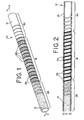
- Figs. 1 and 2 illustrate a generally hollow or tubular structure according to the present invention.
- tubular and “tube” are to be construed broadly and are not limited to a structure that is a right cylinder or strictly circumferential in cross-section or of a uniform cross-section throughout its length.
- the tubular article, member or device is generally designated at 10 and shown as a substantially right cylindrical structure.
- the tubular device 10 may have a tapered or curved outer surface without departing from the scope of the present invention.
- the tubular device 10 is adapted to be received by a body vessel as a component or part of a medical device guidewire, detachment system, deployment system or catheter or other medical instrument or device as generally discussed herein.
- the illustrated tubular device 10 is comprised of two separate metal pieces 12 and 14, substantially comprised of different metals having different performance characteristics, that are joined at an elongated joint or junction 16.
- the term "join" and its derivatives refer to affixation of at least a portion of the first piece 12 to the second piece 14 at the joint 16.
- Providing the two pieces 12 and 14 in an alternating pattern without affixing them to each other is insufficient, because the pieces 12 and 14 can separate from each other, thereby dissolving the joint 16.
- the pieces 12 and 14 are not sealed together at the joint 16, then the open seams therebetween will prevent the tubular device 10 from performing a number of common applications, such as fluid transfer, guidance, and containment.
- merely wrapping one piece around the other at the joint is insufficient and has the negative effect of increasing the outer diameter D of the tubular device 10, which increased size makes it more difficult to maneuver the device 10 through a body vessel.
- the first and second pieces 12 and 14 each typically has a construction along the lines of a tube 18, illustrated in Fig. 3, having a spiral-cut section 20 that defines a plurality of coils 22. While a substantially helical incision is preferred, it will be understood by those of ordinary skill in the art that the spiral-cut section 20 need not be defined by a strictly helical incision, but other shapes may be practiced without departing from the scope of the present invention. Hence, when used herein, the term "spiral-cut section" does not limit the tube 18 to a particular geometry.
- any of a number of cutting methods may be employed to create the spiral-cut section 20, depending on the metal itself, the metal to which it will be joined, the joinder means to be employed, the thickness of the tube 18, the intended use of the device 10 ultimately produced, the machinery available, cost and time constraints, and other factors. Selection of a suitable cutting method based on these factors is within the capabilities of one of ordinary skill in the art.
- the spiral-cut section 20 may be a discrete region of the tube 18, at an end or somewhere between the ends, but it may also extend along the length of the tube 18, such that the tube resembles a helical coil.
- the pieces 12 and 14 typically are not provided as a typical manufactured helical coil, i.e., drawn or cold-worked or wound, for a number of reasons. These are exemplified by the following. First, it is more difficult to manufacture a satisfactory coil of the appropriate size than a tube of the same size. Second, it is much easier to create coils having a varying width W or an irregular shape by the present invention than by typical coil-forming methods.
- first and second pieces 12 and 14 are custom cutting spiral-cut sections 20 that are specially suited for joinder with each other.
- a commercially available helical coil it is within the scope of the present invention to use such a coil in combination with a tube 18 according to the preceding description.
- the joint 16 is a tubular portion that is characterized by the two pieces 12 and 14 being arranged in a generally alternating pattern.
- the joint 16 may have a tapered or curved profile without departing from the scope of the present invention.
- the respective spiral-cut sections 20 of the first and second metal tubes are configured such that they can be combined into the pattern of Figs. 1 and 2.
- the intermeshed portions of the two pieces 12 and 14 define a single layer, best illustrated in Fig. 2, and are joined together at the joint 16 by a suitable means, such as solder or adhesive, which is designated at 26.
- the respective outer and inner diameters of the two pieces 12 and 14 are substantially identical due to performance and manufacturing concerns, which are described in greater detail herein. It will be appreciated by those of ordinary skill in the art that the alternating pattern results in a larger joinder region than would typically be achieved by joining two separate pieces using known means, such as a butt weld. Thus, a device according to the present invention is able to achieve a more durable joint without disadvantageously increasing the outer diameter.
- the joint 16 is typically located at a discrete region between the ends of the device 10, which region separates a first section 28, substantially defined by a portion of the first piece 12, and a second section 30, substantially defined by a portion of the second piece 14.
- the first and second sections 28 and 30 typically correspond to the uncut section 24 of the tube 18 of Fig. 3, as shown in Fig. 4 but, as shown in Figs. 1 and 2, they may be at least partially spiral-cut.
- the specific geometry and composition of the first and second sections 28 and 30 will depend on the nature of the medical instrument in which the tubular device 10 will eventually be incorporated.
- the first section 28 will exhibit performance characteristics of the first metal
- the second section 30 will exhibit performance characteristics of the second metal
- the joint 16 will exhibit a variation of the performance characteristics of the first and second metals.
- Some or all of the turns of one metal may be wider than the turns of the other metal, such that the joint 16 will exhibit performance characteristics more similar to one metal (typically the metal tube having the wider turns) than the other.
- the first metal has superelastic properties.
- the term “superelastic” is intended to refer to materials that typically exhibit both martensitic and austenitic properties and that have austenitic properties in use.
- the first metal is a nitinol material having superelastic properties.
- the nitinol composition has a transformation temperature lower than body temperature, such that the nitinol material is in a austentic state when in use in vivo.
- the second metal is stainless steel, in which case the first metal is more flexible than the second metal at human body temperature.
- the device may be provided in a number of variations, such as by providing a plurality of discrete joints 16 spaced along its length.
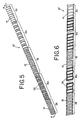
- Figs. 5 and 6 illustrate a tubular device 10' having a first joint 16a and a second joint 16b that are separated by an intermediate section 32.
- the intermediate section 32 may be cut, as illustrated in Figs. 5 and 6, or uncut and be a part of either the first piece 12, as illustrated in Figs. 5 and 6, or the second piece 14.
- the joint 16 may define the entire length of the tubular device, in which case the entire device will exhibit a combination of the performance characteristics of the first and second metals.
- the joint 16 and/or other portions of the tubular device may be tapered or curved, rather than having the generally uniform, right cylindrical outer diameter of Figs. 1 and 2.
- a tubular device 10" may be provided with a length of shrink tubing 34 instead of the joinder means 26 of Figs. 1 and 2 to join the first and second pieces 12 and 14. If shrink tubing 34 is used, then it is preferably selected to provide a fluid seal to allow the joint 16 to perform a wider variety of functions, such as fluid injection and containment.
- the device is provided with a radiopaque material to allow for improved positioning of a device within the body.
- a radiopaque material there are several ways to provide the radiopaque material.
- radiopaque bars or rivets 36 may be placed into or onto one or both of the pieces 12 and 14 before or after they are joined.
- Fig. 4 shows a preferred embodiment in which a third piece 38 is provided that is substantially comprised of a radiopaque material.
- the third piece 38 is joined to the first and second pieces 12 and 14 at the joint 16 in an alternating pattern. It will be appreciated that this is similar to the alternating pattern of Figs. 1 and 2, except that three pieces are intermeshed instead of just two.
- the use of a third piece 38 rather than bars or rivets 36 may be preferred, because it may be incorporated without increasing the outer diameter D of the device.
- the third piece 38 whether provided as a tube 18 according to Fig. 3 or as a filament or coil or the like, may be less elongated than the first and second pieces 12 and 14, such that the radiopaque material resides wholly or primarily within the joint 16.
- the radiopaque material is a metal, such as platinum.
- the first piece 12 and the second piece 14 and, if provided, the third piece 38 are intermeshed. This is typically accomplished by stretching the spiral-cut sections 20, thereby increasing their pitch and allowing them to be fit together in a single-layer, alternating pattern that defines the joint 16. Then, the portions of the spiral-cut sections 20 within the joint 16 are joined by suitable means.
- this process is performed with the aid of a mandrel, not illustrated, that is received by the device 10.
- the mandrel may be placed within the lumen of the device 10 before or after the spiral-cut sections 20 are intermeshed, but it should be in place before they are joined.
- the mandrel ensures that the lumen remains open during and after joinder.
- the mandrel typically is circular in cross-section, but may be tapered, curved, or irregularly shaped in order to conform to the final shape or cross-section needed for the tubular device 10.
- formation of the joint 16 on the mandrel can be simplified by providing pieces 12 and 14 with substantially identical outer and inner diameters, because the pieces 12 and 14 will lay smoothly and evenly over the mandrel.
Landscapes
- Health & Medical Sciences (AREA)
- Life Sciences & Earth Sciences (AREA)
- Biophysics (AREA)
- Pulmonology (AREA)
- Engineering & Computer Science (AREA)
- Anesthesiology (AREA)
- Biomedical Technology (AREA)
- Heart & Thoracic Surgery (AREA)
- Hematology (AREA)
- Animal Behavior & Ethology (AREA)
- General Health & Medical Sciences (AREA)
- Public Health (AREA)
- Veterinary Medicine (AREA)
- Media Introduction/Drainage Providing Device (AREA)
- Materials For Medical Uses (AREA)
Applications Claiming Priority (1)
| Application Number | Priority Date | Filing Date | Title |
|---|---|---|---|
| US11/391,740 US7785317B2 (en) | 2006-03-29 | 2006-03-29 | Joined metal tubing and method of manufacture |
Publications (2)
| Publication Number | Publication Date |
|---|---|
| EP1839697A1 true EP1839697A1 (fr) | 2007-10-03 |
| EP1839697B1 EP1839697B1 (fr) | 2010-09-08 |
Family
ID=38066670
Family Applications (1)
| Application Number | Title | Priority Date | Filing Date |
|---|---|---|---|
| EP07251265A Active EP1839697B1 (fr) | 2006-03-29 | 2007-03-24 | Tubage métallique assemblé |
Country Status (4)
| Country | Link |
|---|---|
| US (1) | US7785317B2 (fr) |
| EP (1) | EP1839697B1 (fr) |
| JP (1) | JP5111916B2 (fr) |
| DE (1) | DE602007008968D1 (fr) |
Cited By (8)
| Publication number | Priority date | Publication date | Assignee | Title |
|---|---|---|---|---|
| WO2009054972A1 (fr) * | 2007-10-27 | 2009-04-30 | Salviac Limited | Fil-guide en nitinol |
| WO2014066439A1 (fr) * | 2012-10-22 | 2014-05-01 | Medtronic Ardian Luxembourg Sarl | Cathéters à flexibilité accrue et dispositifs associés, systèmes et procédés |
| WO2014077881A1 (fr) * | 2012-11-14 | 2014-05-22 | Hollister Incorporated | Cathéters urinaires ayant une flexibilité variable |
| EP3069750A1 (fr) * | 2015-03-12 | 2016-09-21 | Cook Medical Technologies LLC | Guide de fil hybride flexible |
| CN107297015A (zh) * | 2017-06-26 | 2017-10-27 | 苏州卡睿知光电科技有限公司 | 一种医用支撑导管 |
| CN107297014A (zh) * | 2017-06-26 | 2017-10-27 | 苏州卡睿知光电科技有限公司 | 一种支架置入用支撑导管 |
| US10188829B2 (en) | 2012-10-22 | 2019-01-29 | Medtronic Ardian Luxembourg S.A.R.L. | Catheters with enhanced flexibility and associated devices, systems, and methods |
| US10548663B2 (en) | 2013-05-18 | 2020-02-04 | Medtronic Ardian Luxembourg S.A.R.L. | Neuromodulation catheters with shafts for enhanced flexibility and control and associated devices, systems, and methods |
Families Citing this family (30)
| Publication number | Priority date | Publication date | Assignee | Title |
|---|---|---|---|---|
| US8458879B2 (en) * | 2001-07-03 | 2013-06-11 | Advanced Bio Prosthetic Surfaces, Ltd., A Wholly Owned Subsidiary Of Palmaz Scientific, Inc. | Method of fabricating an implantable medical device |
| US9339632B2 (en) * | 2006-09-27 | 2016-05-17 | Boston Scientific Scimed, Inc. | Catheter shaft designs |
| JP5430065B2 (ja) * | 2007-12-28 | 2014-02-26 | テルモ株式会社 | ガイドワイヤ |
| US7815376B2 (en) * | 2008-06-30 | 2010-10-19 | Intuitive Surgical Operations, Inc. | Fixture for shape-sensing optical fiber in a kinematic chain |
| US11406791B2 (en) | 2009-04-03 | 2022-08-09 | Scientia Vascular, Inc. | Micro-fabricated guidewire devices having varying diameters |
| US8468919B2 (en) | 2008-12-08 | 2013-06-25 | Next Vascular, Llc | Micro-cutting machine for forming cuts in products |
| US12220538B2 (en) | 2008-12-08 | 2025-02-11 | Scientia Vascular, Inc. | Micro-fabricated intravascular devices having varying diameters |
| US9006606B2 (en) * | 2010-03-05 | 2015-04-14 | Arthrex, Inc. | Flexible drill and method of joining nitinol to dissimilar metals |
| US11007345B2 (en) * | 2016-10-05 | 2021-05-18 | Orbusneich Medical Pte. Ltd. | Modular vascular catheter |
| US11207502B2 (en) | 2016-07-18 | 2021-12-28 | Scientia Vascular, Llc | Guidewire devices having shapeable tips and bypass cuts |
| US11052228B2 (en) | 2016-07-18 | 2021-07-06 | Scientia Vascular, Llc | Guidewire devices having shapeable tips and bypass cuts |
| US10646689B2 (en) | 2016-07-29 | 2020-05-12 | Cephea Valve Technologies, Inc. | Mechanical interlock for catheters |
| US11109967B2 (en) | 2016-08-29 | 2021-09-07 | Cephea Valve Technologies, Inc. | Systems and methods for loading and deploying an intravascular device |
| US11452541B2 (en) * | 2016-12-22 | 2022-09-27 | Scientia Vascular, Inc. | Intravascular device having a selectively deflectable tip |
| EP4257173A3 (fr) | 2017-05-26 | 2023-11-29 | Scientia Vascular, Inc. | Dispositif medical microfabrique presentant un agencement de coupe non helicoidal |
| US11305095B2 (en) | 2018-02-22 | 2022-04-19 | Scientia Vascular, Llc | Microfabricated catheter having an intermediate preferred bending section |
| US12011555B2 (en) | 2019-01-15 | 2024-06-18 | Scientia Vascular, Inc. | Guidewire with core centering mechanism |
| US12623049B2 (en) | 2019-05-02 | 2026-05-12 | Scientia Vascular, Inc. | Intravascular device with enhanced one-beam cut pattern |
| CN111317906B (zh) * | 2019-05-16 | 2022-06-14 | 东莞科威医疗器械有限公司 | 医用插管、带插芯股动静脉插管与医用插管的成型方法 |
| US11077285B2 (en) | 2019-06-15 | 2021-08-03 | Maduro Discovery, Llc | Catheter construction |
| US12343485B2 (en) | 2020-01-23 | 2025-07-01 | Scientia Vascular, Inc. | High torque guidewire device |
| US12178975B2 (en) | 2020-01-23 | 2024-12-31 | Scientia Vascular, Inc. | Guidewire having enlarged, micro-fabricated distal section |
| EP4138634A4 (fr) | 2020-04-20 | 2024-02-21 | Surmodics MD, LLC | Cathéter à ballonnet radial |
| US12296112B2 (en) | 2020-10-05 | 2025-05-13 | Scientia Vascular, Inc. | Microfabricated catheter devices with high axial strength |
| CA3197752A1 (fr) | 2020-11-26 | 2022-06-02 | Avia Vascular, Llc | Dispositifs, systemes et procedes de prelevement sanguin |
| JP7693160B2 (ja) * | 2021-05-13 | 2025-06-17 | 二九精密機械工業株式会社 | 連結組子部品 |
| JP7664113B2 (ja) * | 2021-07-30 | 2025-04-17 | 朝日インテック株式会社 | サポートデバイス |
| WO2023034492A1 (fr) | 2021-09-01 | 2023-03-09 | Surmodics Md, Llc | Cathéter à ballonnet à accès radial |
| US12064156B2 (en) | 2023-01-09 | 2024-08-20 | John F. Krumme | Dynamic compression fixation devices |
| CA3263768A1 (fr) | 2022-07-30 | 2024-02-08 | Maduro Discovery, Llc | Construction de cathéter |
Citations (4)
| Publication number | Priority date | Publication date | Assignee | Title |
|---|---|---|---|---|
| US5437288A (en) * | 1992-09-04 | 1995-08-01 | Mayo Foundation For Medical Education And Research | Flexible catheter guidewire |
| US20050283134A1 (en) * | 2004-06-22 | 2005-12-22 | Scimed Life Systems, Inc. | Catheter shaft with improved manifold bond |
| EP1611914A1 (fr) * | 2004-06-29 | 2006-01-04 | Cordis Neurovascular, Inc. | Conception d'arbre pour cathéter à ballonnet |
| EP1709987A1 (fr) * | 2005-04-07 | 2006-10-11 | Creganna Technologies Limited | Ensemble de cathéter dirigeable |
Family Cites Families (89)
| Publication number | Priority date | Publication date | Assignee | Title |
|---|---|---|---|---|
| US2580872A (en) | 1946-10-19 | 1952-01-01 | Clarence L Wise | Ventilator for hay and grain containers |
| US3128536A (en) * | 1961-01-19 | 1964-04-14 | Driam S A Fa | Method for producing hollow bodies from strips |
| US3854473A (en) | 1973-05-29 | 1974-12-17 | Olympus Optical Co | Stilet for endoscopes |
| US4215703A (en) | 1978-08-29 | 1980-08-05 | Willson James K V | Variable stiffness guide wire |
| US4390599A (en) | 1980-07-31 | 1983-06-28 | Raychem Corporation | Enhanced recovery memory metal device |
| US4430083A (en) * | 1981-03-06 | 1984-02-07 | American Hospital Supply Corporation | Infusion catheter |
| JPH01145074A (ja) | 1987-12-01 | 1989-06-07 | Terumo Corp | バルーンカテーテル |
| US4864824A (en) | 1988-10-31 | 1989-09-12 | American Telephone And Telegraph Company, At&T Bell Laboratories | Thin film shape memory alloy and method for producing |
| US4981756A (en) | 1989-03-21 | 1991-01-01 | Vac-Tec Systems, Inc. | Method for coated surgical instruments and tools |
| US4922924A (en) * | 1989-04-27 | 1990-05-08 | C. R. Bard, Inc. | Catheter guidewire with varying radiopacity |
| US5178957A (en) | 1989-05-02 | 1993-01-12 | Minnesota Mining And Manufacturing Company | Noble metal-polymer composites and flexible thin-film conductors prepared therefrom |
| US5061914A (en) | 1989-06-27 | 1991-10-29 | Tini Alloy Company | Shape-memory alloy micro-actuator |
| US5082359A (en) | 1989-11-28 | 1992-01-21 | Epion Corporation | Diamond films and method of growing diamond films on nondiamond substrates |
| US5108819A (en) | 1990-02-14 | 1992-04-28 | Eli Lilly And Company | Thin film electrical component |
| US5174302A (en) | 1990-12-04 | 1992-12-29 | Cordis Corporation | Variable radiopacity guidewire with spaced highly radiopaque regions |
| US5197978B1 (en) | 1991-04-26 | 1996-05-28 | Advanced Coronary Tech | Removable heat-recoverable tissue supporting device |
| US5203804A (en) | 1991-07-18 | 1993-04-20 | Minnesota Mining And Manufacturing Company | Coated dental article |
| US5605162A (en) | 1991-10-15 | 1997-02-25 | Advanced Cardiovascular Systems, Inc. | Method for using a variable stiffness guidewire |
| WO1993007924A1 (fr) | 1991-10-18 | 1993-04-29 | Spire Corporation | Revetements bactericides s'appliquant a des implants |
| US5685961A (en) | 1992-03-27 | 1997-11-11 | P & D Medical Coatings, Inc. | Method for fabrication of metallized medical devices |
| US5540712A (en) | 1992-05-01 | 1996-07-30 | Nitinol Medical Technologies, Inc. | Stent and method and apparatus for forming and delivering the same |
| US5681575A (en) | 1992-05-19 | 1997-10-28 | Westaim Technologies Inc. | Anti-microbial coating for medical devices |
| GEP20002074B (en) | 1992-05-19 | 2000-05-10 | Westaim Tech Inc Ca | Modified Material and Method for its Production |
| US5382261A (en) | 1992-09-01 | 1995-01-17 | Expandable Grafts Partnership | Method and apparatus for occluding vessels |
| US5334216A (en) | 1992-12-10 | 1994-08-02 | Howmedica Inc. | Hemostatic plug |
| US5607463A (en) | 1993-03-30 | 1997-03-04 | Medtronic, Inc. | Intravascular medical device |
| WO1994025637A1 (fr) | 1993-04-23 | 1994-11-10 | Etex Corporation | Procede de revetement de dispositifs medicaux et dispositifs presentant un tel revetement |
| US5360397A (en) | 1993-07-02 | 1994-11-01 | Corvita Corporation | Hemodiaylsis catheter and catheter assembly |
| US5735892A (en) | 1993-08-18 | 1998-04-07 | W. L. Gore & Associates, Inc. | Intraluminal stent graft |
| CA2136455C (fr) | 1993-11-18 | 1999-06-29 | Robert Edward Burrell | Procede d'induction d'un effet anti-microbien avec des ions d'argent complexes |
| US5591129A (en) | 1994-03-02 | 1997-01-07 | Scimed Life Systems, Inc. | Perfusion balloon angioplasty catheter |
| US5629077A (en) | 1994-06-27 | 1997-05-13 | Advanced Cardiovascular Systems, Inc. | Biodegradable mesh and film stent |
| US5984905A (en) | 1994-07-11 | 1999-11-16 | Southwest Research Institute | Non-irritating antimicrobial coating for medical implants and a process for preparing same |
| US5575816A (en) | 1994-08-12 | 1996-11-19 | Meadox Medicals, Inc. | High strength and high density intraluminal wire stent |
| US6451047B2 (en) | 1995-03-10 | 2002-09-17 | Impra, Inc. | Encapsulated intraluminal stent-graft and methods of making same |
| US5744958A (en) | 1995-11-07 | 1998-04-28 | Iti Medical Technologies, Inc. | Instrument having ultra-thin conductive coating and method for magnetic resonance imaging of such instrument |
| US5669977A (en) | 1995-12-22 | 1997-09-23 | Lam Research Corporation | Shape memory alloy lift pins for semiconductor processing equipment |
| US5925038A (en) | 1996-01-19 | 1999-07-20 | Ep Technologies, Inc. | Expandable-collapsible electrode structures for capacitive coupling to tissue |
| US5843289A (en) | 1996-01-22 | 1998-12-01 | Etex Corporation | Surface modification of medical implants |
| DE59600146D1 (de) * | 1996-05-03 | 1998-05-14 | Schneider Europ Ag | Verfahren zur Herstellung eines Führungsdrahtes und Führungsdraht |
| US5951586A (en) | 1996-05-15 | 1999-09-14 | Medtronic, Inc. | Intraluminal stent |
| US6068623A (en) * | 1997-03-06 | 2000-05-30 | Percusurge, Inc. | Hollow medical wires and methods of constructing same |
| US5762615A (en) | 1996-06-04 | 1998-06-09 | Cordis Corporation | Guideware having a distal tip with variable flexibility |
| US5928279A (en) | 1996-07-03 | 1999-07-27 | Baxter International Inc. | Stented, radially expandable, tubular PTFE grafts |
| US6174329B1 (en) | 1996-08-22 | 2001-01-16 | Advanced Cardiovascular Systems, Inc. | Protective coating for a stent with intermediate radiopaque coating |
| DE19653720A1 (de) | 1996-12-10 | 1998-06-18 | Biotronik Mess & Therapieg | Stent |
| US7073504B2 (en) | 1996-12-18 | 2006-07-11 | Ams Research Corporation | Contraceptive system and method of use |
| IT1291001B1 (it) | 1997-01-09 | 1998-12-14 | Sorin Biomedica Cardio Spa | Stent per angioplastica e suo procedimento di produzione |
| US6183420B1 (en) | 1997-06-20 | 2001-02-06 | Medtronic Ave, Inc. | Variable stiffness angioplasty guide wire |
| US6113557A (en) | 1997-06-20 | 2000-09-05 | Medtronic Ave, Inc. | Variable stiffness angioplasty guide wire |
| US5947940A (en) * | 1997-06-23 | 1999-09-07 | Beisel; Robert F. | Catheter reinforced to prevent luminal collapse and tensile failure thereof |
| US5908409A (en) | 1997-08-26 | 1999-06-01 | Mcghan Medical Corporation | Tubing plug |
| US6043451A (en) | 1997-11-06 | 2000-03-28 | Promet Technologies, Inc. | Plasma spraying of nickel-titanium compound |
| US6726993B2 (en) | 1997-12-02 | 2004-04-27 | Teer Coatings Limited | Carbon coatings, method and apparatus for applying them, and articles bearing such coatings |
| US6342067B1 (en) | 1998-01-09 | 2002-01-29 | Nitinol Development Corporation | Intravascular stent having curved bridges for connecting adjacent hoops |
| US6447478B1 (en) | 1998-05-15 | 2002-09-10 | Ronald S. Maynard | Thin-film shape memory alloy actuators and processing methods |
| EP1082072B8 (fr) | 1998-06-04 | 2014-03-05 | New York University | Dispositifs endovasculaires a couche mince permettant de traiter et de prevenir un accident cerebrovasculaire |
| WO1999066966A1 (fr) | 1998-06-22 | 1999-12-29 | Anatoly Dosta | Revetement de type film fin pour implant osseux |
| US6203732B1 (en) | 1998-07-02 | 2001-03-20 | Intra Therapeutics, Inc. | Method for manufacturing intraluminal device |
| US6096175A (en) | 1998-07-17 | 2000-08-01 | Micro Therapeutics, Inc. | Thin film stent |
| US6325824B2 (en) | 1998-07-22 | 2001-12-04 | Advanced Cardiovascular Systems, Inc. | Crush resistant stent |
| US6248122B1 (en) | 1999-02-26 | 2001-06-19 | Vascular Architects, Inc. | Catheter with controlled release endoluminal prosthesis |
| US6620172B1 (en) | 1999-07-01 | 2003-09-16 | Medsource Technologies, Inc. | Entraining biological calculi |
| US6322588B1 (en) | 1999-08-17 | 2001-11-27 | St. Jude Medical, Inc. | Medical devices with metal/polymer composites |
| JP4445618B2 (ja) * | 1999-11-15 | 2010-04-07 | 株式会社ハイレックスコーポレーション | 医療用チューブ |
| US6537310B1 (en) | 1999-11-19 | 2003-03-25 | Advanced Bio Prosthetic Surfaces, Ltd. | Endoluminal implantable devices and method of making same |
| US6579246B2 (en) | 1999-12-22 | 2003-06-17 | Sarcos, Lc | Coronary guidewire system |
| US6471721B1 (en) | 1999-12-30 | 2002-10-29 | Advanced Cardiovascular Systems, Inc. | Vascular stent having increased radiopacity and method for making same |
| AU2001231099A1 (en) | 2000-01-24 | 2001-07-31 | Smart Therapeutics, Inc. | Thin-film shape memory alloy device and method |
| WO2001066167A2 (fr) | 2000-03-03 | 2001-09-13 | Chuter Timothy A M | Stents et occluseurs pour gros vaisseaux |
| US6436132B1 (en) | 2000-03-30 | 2002-08-20 | Advanced Cardiovascular Systems, Inc. | Composite intraluminal prostheses |
| US6755794B2 (en) | 2000-04-25 | 2004-06-29 | Synovis Life Technologies, Inc. | Adjustable stylet |
| CA2409003C (fr) | 2000-05-16 | 2010-10-19 | Ortho-Mcneil Pharmaceutical, Inc. | Procede de revetement de dispositifs medicaux par du dioxyde de carbone hypercritique |
| US20020032478A1 (en) | 2000-08-07 | 2002-03-14 | Percardia, Inc. | Myocardial stents and related methods of providing direct blood flow from a heart chamber to a coronary vessel |
| US6805898B1 (en) | 2000-09-28 | 2004-10-19 | Advanced Cardiovascular Systems, Inc. | Surface features of an implantable medical device |
| US6770086B1 (en) | 2000-11-02 | 2004-08-03 | Scimed Life Systems, Inc. | Stent covering formed of porous polytetraflouroethylene |
| WO2002038080A2 (fr) | 2000-11-07 | 2002-05-16 | Advanced Bio Prosthetic Surfaces, Ltd. | Tuteur endoluminal, greffon endoluminal autoporteur et leurs procedes de fabrication |
| US6623504B2 (en) | 2000-12-08 | 2003-09-23 | Scimed Life Systems, Inc. | Balloon catheter with radiopaque distal tip |
| GB0123596D0 (en) | 2001-10-02 | 2001-11-21 | Smiths Group Plc | Medico-surgical devices |
| JP4621409B2 (ja) * | 2001-09-29 | 2011-01-26 | 龍之 河野 | アタッチメントが付属するハンガ及びこのハンガを使用した衣服の吊り下げ方法 |
| US20030066533A1 (en) | 2001-10-05 | 2003-04-10 | Loy Randall A. | Removable fallopian tube plug and associated methods |
| US6652508B2 (en) * | 2001-11-09 | 2003-11-25 | Scimed Life Systems, Inc. | Intravascular microcatheter having hypotube proximal shaft with transition |
| US6929766B2 (en) | 2002-06-14 | 2005-08-16 | Edwards Lifesciences Corporation | Dispense molding method and apparatus for manufacturing cannulae |
| CA2493013C (fr) | 2002-07-25 | 2011-07-19 | Boston Scientific Limited | Dispositif medical d'exploration anatomique et procede de fabrication correspondant |
| US20040143288A1 (en) | 2002-08-27 | 2004-07-22 | Gary Searle | Mechanical occluding and dilation device for a vessel |
| AU2003270817B2 (en) | 2002-09-26 | 2009-09-17 | Vactronix Scientific, Llc | High strength vacuum deposited nitionol alloy films, medical thin film graft materials and method of making same |
| US6970734B2 (en) | 2002-12-02 | 2005-11-29 | Boston Scientific Scimed, Inc. | Flexible marker bands |
| EP1684628B1 (fr) * | 2003-11-21 | 2018-06-13 | St. Jude Medical Coordination Center BVBA | Ensemble de capteur et de fil-guide |
| US7867176B2 (en) * | 2005-12-27 | 2011-01-11 | Cordis Corporation | Variable stiffness guidewire |
-
2006
- 2006-03-29 US US11/391,740 patent/US7785317B2/en active Active
-
2007
- 2007-03-24 EP EP07251265A patent/EP1839697B1/fr active Active
- 2007-03-24 DE DE602007008968T patent/DE602007008968D1/de active Active
- 2007-03-28 JP JP2007085160A patent/JP5111916B2/ja not_active Expired - Fee Related
Patent Citations (4)
| Publication number | Priority date | Publication date | Assignee | Title |
|---|---|---|---|---|
| US5437288A (en) * | 1992-09-04 | 1995-08-01 | Mayo Foundation For Medical Education And Research | Flexible catheter guidewire |
| US20050283134A1 (en) * | 2004-06-22 | 2005-12-22 | Scimed Life Systems, Inc. | Catheter shaft with improved manifold bond |
| EP1611914A1 (fr) * | 2004-06-29 | 2006-01-04 | Cordis Neurovascular, Inc. | Conception d'arbre pour cathéter à ballonnet |
| EP1709987A1 (fr) * | 2005-04-07 | 2006-10-11 | Creganna Technologies Limited | Ensemble de cathéter dirigeable |
Cited By (11)
| Publication number | Priority date | Publication date | Assignee | Title |
|---|---|---|---|---|
| WO2009054972A1 (fr) * | 2007-10-27 | 2009-04-30 | Salviac Limited | Fil-guide en nitinol |
| WO2014066439A1 (fr) * | 2012-10-22 | 2014-05-01 | Medtronic Ardian Luxembourg Sarl | Cathéters à flexibilité accrue et dispositifs associés, systèmes et procédés |
| WO2014066432A3 (fr) * | 2012-10-22 | 2014-06-12 | Medtronic Ardian Luxembourg Sarl | Cathéters à flexibilité accrue et dispositifs associés, systèmes et procédés |
| US10188829B2 (en) | 2012-10-22 | 2019-01-29 | Medtronic Ardian Luxembourg S.A.R.L. | Catheters with enhanced flexibility and associated devices, systems, and methods |
| US11147948B2 (en) | 2012-10-22 | 2021-10-19 | Medtronic Ardian Luxembourg S.A.R.L. | Catheters with enhanced flexibility and associated devices, systems, and methods |
| WO2014077881A1 (fr) * | 2012-11-14 | 2014-05-22 | Hollister Incorporated | Cathéters urinaires ayant une flexibilité variable |
| US10029071B2 (en) | 2012-11-14 | 2018-07-24 | Hollister Incorporated | Urinary catheters having varying flexibility |
| US10548663B2 (en) | 2013-05-18 | 2020-02-04 | Medtronic Ardian Luxembourg S.A.R.L. | Neuromodulation catheters with shafts for enhanced flexibility and control and associated devices, systems, and methods |
| EP3069750A1 (fr) * | 2015-03-12 | 2016-09-21 | Cook Medical Technologies LLC | Guide de fil hybride flexible |
| CN107297015A (zh) * | 2017-06-26 | 2017-10-27 | 苏州卡睿知光电科技有限公司 | 一种医用支撑导管 |
| CN107297014A (zh) * | 2017-06-26 | 2017-10-27 | 苏州卡睿知光电科技有限公司 | 一种支架置入用支撑导管 |
Also Published As
| Publication number | Publication date |
|---|---|
| US7785317B2 (en) | 2010-08-31 |
| JP2007260403A (ja) | 2007-10-11 |
| US20070233039A1 (en) | 2007-10-04 |
| EP1839697B1 (fr) | 2010-09-08 |
| JP5111916B2 (ja) | 2013-01-09 |
| DE602007008968D1 (de) | 2010-10-21 |
Similar Documents
| Publication | Publication Date | Title |
|---|---|---|
| EP1839697B1 (fr) | Tubage métallique assemblé | |
| EP1985244B1 (fr) | Système de dispositif médical d'intervention doté d'une section rainurée et d'un marqueur radio-opaque et son procédé de fabrication | |
| EP1803484B1 (fr) | Fil de guidage à rigidité variable | |
| US8864789B2 (en) | Interventional medical device system having a spiral section and radiopaque marker and method of making the same | |
| US10315018B2 (en) | Catheter shaft designs | |
| US7708704B2 (en) | Interventional medical device component having an interrupted spiral section and method of making the same | |
| JP2022116350A (ja) | 累加柔軟性カテーテル支持フレーム | |
| JP5666295B2 (ja) | 多線条ケーブルカテーテル | |
| JP7349357B2 (ja) | モジュール式血管カテーテル | |
| HK1243663A1 (zh) | 血管再进入导管 | |
| JP2011067660A5 (fr) | ||
| JP2010527259A5 (fr) | ||
| CN107666936A (zh) | 用于改善跨越异种金属焊接接合部的刚度过渡的机构 | |
| EP2561838B1 (fr) | Cathéter à fil de câble court | |
| WO2013112272A1 (fr) | Marqueur radio-opaque pour un cathéter | |
| JP5664040B2 (ja) | ステントデリバリーカテーテル、アウターシャフトの製造方法、および、ステントデリバリーカテーテルの製造方法 | |
| US9782560B2 (en) | Short wire cable catheter | |
| EP4279113B1 (fr) | Structure de corps de cathéter multifilaire |
Legal Events
| Date | Code | Title | Description |
|---|---|---|---|
| PUAI | Public reference made under article 153(3) epc to a published international application that has entered the european phase |
Free format text: ORIGINAL CODE: 0009012 |
|
| 17P | Request for examination filed |
Effective date: 20070730 |
|
| AK | Designated contracting states |
Kind code of ref document: A1 Designated state(s): AT BE BG CH CY CZ DE DK EE ES FI FR GB GR HU IE IS IT LI LT LU LV MC MT NL PL PT RO SE SI SK TR |
|
| AX | Request for extension of the european patent |
Extension state: AL BA HR MK YU |
|
| AKX | Designation fees paid |
Designated state(s): BE DE GB IE NL |
|
| GRAP | Despatch of communication of intention to grant a patent |
Free format text: ORIGINAL CODE: EPIDOSNIGR1 |
|
| RTI1 | Title (correction) |
Free format text: JOINED METAL TUBING |
|
| RAP1 | Party data changed (applicant data changed or rights of an application transferred) |
Owner name: CORDIS DEVELOPMENT CORPORATION |
|
| GRAS | Grant fee paid |
Free format text: ORIGINAL CODE: EPIDOSNIGR3 |
|
| GRAA | (expected) grant |
Free format text: ORIGINAL CODE: 0009210 |
|
| AK | Designated contracting states |
Kind code of ref document: B1 Designated state(s): BE DE GB IE NL |
|
| REG | Reference to a national code |
Ref country code: GB Ref legal event code: FG4D |
|
| REG | Reference to a national code |
Ref country code: IE Ref legal event code: FG4D |
|
| REF | Corresponds to: |
Ref document number: 602007008968 Country of ref document: DE Date of ref document: 20101021 Kind code of ref document: P |
|
| REG | Reference to a national code |
Ref country code: NL Ref legal event code: T3 |
|
| PLBE | No opposition filed within time limit |
Free format text: ORIGINAL CODE: 0009261 |
|
| STAA | Information on the status of an ep patent application or granted ep patent |
Free format text: STATUS: NO OPPOSITION FILED WITHIN TIME LIMIT |
|
| 26N | No opposition filed |
Effective date: 20110609 |
|
| REG | Reference to a national code |
Ref country code: NL Ref legal event code: SD Effective date: 20110819 |
|
| REG | Reference to a national code |
Ref country code: GB Ref legal event code: 732E Free format text: REGISTERED BETWEEN 20110825 AND 20110831 |
|
| BECA | Be: change of holder's address |
Owner name: CODMAN & SHURTLEFF, INC.325 PARAMOUNT DRIVE,RAYNHA Effective date: 20110920 |
|
| BECH | Be: change of holder |
Owner name: CODMAN & SHURTLEFF, INC. Effective date: 20110920 |
|
| REG | Reference to a national code |
Ref country code: DE Ref legal event code: R097 Ref document number: 602007008968 Country of ref document: DE Effective date: 20110609 |
|
| REG | Reference to a national code |
Ref country code: DE Ref legal event code: R082 Ref document number: 602007008968 Country of ref document: DE Representative=s name: BOEHMERT & BOEHMERT, DE |
|
| REG | Reference to a national code |
Ref country code: DE Ref legal event code: R081 Ref document number: 602007008968 Country of ref document: DE Owner name: CODMAN & SHURTLEFF, INC., RAYNHAM, US Free format text: FORMER OWNER: CORDIS DEVELOPMENT CORP., MIAMI LAKES, FLA., US Effective date: 20111014 Ref country code: DE Ref legal event code: R082 Ref document number: 602007008968 Country of ref document: DE Representative=s name: BOEHMERT & BOEHMERT ANWALTSPARTNERSCHAFT MBB -, DE Effective date: 20111014 Ref country code: DE Ref legal event code: R082 Ref document number: 602007008968 Country of ref document: DE Representative=s name: BOEHMERT & BOEHMERT, DE Effective date: 20111014 Ref country code: DE Ref legal event code: R081 Ref document number: 602007008968 Country of ref document: DE Owner name: CODMAN & SHURTLEFF, INC., US Free format text: FORMER OWNER: CORDIS DEVELOPMENT CORP., MIAMI LAKES, US Effective date: 20111014 |
|
| PGFP | Annual fee paid to national office [announced via postgrant information from national office to epo] |
Ref country code: DE Payment date: 20170321 Year of fee payment: 11 Ref country code: NL Payment date: 20170320 Year of fee payment: 11 |
|
| PGFP | Annual fee paid to national office [announced via postgrant information from national office to epo] |
Ref country code: BE Payment date: 20170213 Year of fee payment: 11 Ref country code: IE Payment date: 20170309 Year of fee payment: 11 |
|
| REG | Reference to a national code |
Ref country code: DE Ref legal event code: R119 Ref document number: 602007008968 Country of ref document: DE |
|
| REG | Reference to a national code |
Ref country code: NL Ref legal event code: MM Effective date: 20180401 |
|
| REG | Reference to a national code |
Ref country code: BE Ref legal event code: MM Effective date: 20180331 |
|
| REG | Reference to a national code |
Ref country code: IE Ref legal event code: MM4A |
|
| PG25 | Lapsed in a contracting state [announced via postgrant information from national office to epo] |
Ref country code: NL Free format text: LAPSE BECAUSE OF NON-PAYMENT OF DUE FEES Effective date: 20180401 |
|
| PG25 | Lapsed in a contracting state [announced via postgrant information from national office to epo] |
Ref country code: IE Free format text: LAPSE BECAUSE OF NON-PAYMENT OF DUE FEES Effective date: 20180324 Ref country code: DE Free format text: LAPSE BECAUSE OF NON-PAYMENT OF DUE FEES Effective date: 20181002 |
|
| PG25 | Lapsed in a contracting state [announced via postgrant information from national office to epo] |
Ref country code: BE Free format text: LAPSE BECAUSE OF NON-PAYMENT OF DUE FEES Effective date: 20180331 |
|
| PGFP | Annual fee paid to national office [announced via postgrant information from national office to epo] |
Ref country code: GB Payment date: 20260202 Year of fee payment: 20 |