EP1839843B1 - Procédé de fabrication d'un composant plastique structuré - Google Patents
Procédé de fabrication d'un composant plastique structuré Download PDFInfo
- Publication number
- EP1839843B1 EP1839843B1 EP20070006314 EP07006314A EP1839843B1 EP 1839843 B1 EP1839843 B1 EP 1839843B1 EP 20070006314 EP20070006314 EP 20070006314 EP 07006314 A EP07006314 A EP 07006314A EP 1839843 B1 EP1839843 B1 EP 1839843B1
- Authority
- EP
- European Patent Office
- Prior art keywords
- structuring
- layer
- vault
- structuring layer
- plastic component
- Prior art date
- Legal status (The legal status is an assumption and is not a legal conclusion. Google has not performed a legal analysis and makes no representation as to the accuracy of the status listed.)
- Ceased
Links
Images


Classifications
-
- B—PERFORMING OPERATIONS; TRANSPORTING
- B29—WORKING OF PLASTICS; WORKING OF SUBSTANCES IN A PLASTIC STATE IN GENERAL
- B29C—SHAPING OR JOINING OF PLASTICS; SHAPING OF MATERIAL IN A PLASTIC STATE, NOT OTHERWISE PROVIDED FOR; AFTER-TREATMENT OF THE SHAPED PRODUCTS, e.g. REPAIRING
- B29C70/00—Shaping composites, i.e. plastics material comprising reinforcements, fillers or preformed parts, e.g. inserts
- B29C70/04—Shaping composites, i.e. plastics material comprising reinforcements, fillers or preformed parts, e.g. inserts comprising reinforcements only, e.g. self-reinforcing plastics
- B29C70/28—Shaping operations therefor
- B29C70/40—Shaping or impregnating by compression not applied
- B29C70/50—Shaping or impregnating by compression not applied for producing articles of indefinite length, e.g. prepregs, sheet moulding compounds [SMC] or cross moulding compounds [XMC]
- B29C70/504—Shaping or impregnating by compression not applied for producing articles of indefinite length, e.g. prepregs, sheet moulding compounds [SMC] or cross moulding compounds [XMC] using rollers or pressure bands
-
- B—PERFORMING OPERATIONS; TRANSPORTING
- B29—WORKING OF PLASTICS; WORKING OF SUBSTANCES IN A PLASTIC STATE IN GENERAL
- B29C—SHAPING OR JOINING OF PLASTICS; SHAPING OF MATERIAL IN A PLASTIC STATE, NOT OTHERWISE PROVIDED FOR; AFTER-TREATMENT OF THE SHAPED PRODUCTS, e.g. REPAIRING
- B29C53/00—Shaping by bending, folding, twisting, straightening or flattening; Apparatus therefor
- B29C53/02—Bending or folding
- B29C53/04—Bending or folding of plates or sheets
-
- B—PERFORMING OPERATIONS; TRANSPORTING
- B29—WORKING OF PLASTICS; WORKING OF SUBSTANCES IN A PLASTIC STATE IN GENERAL
- B29C—SHAPING OR JOINING OF PLASTICS; SHAPING OF MATERIAL IN A PLASTIC STATE, NOT OTHERWISE PROVIDED FOR; AFTER-TREATMENT OF THE SHAPED PRODUCTS, e.g. REPAIRING
- B29C53/00—Shaping by bending, folding, twisting, straightening or flattening; Apparatus therefor
- B29C53/22—Corrugating
- B29C53/24—Corrugating of plates or sheets
Definitions
- the invention relates to a method for producing a structured plastic component, in particular a method for self-structuring a fiber-reinforced, in particular layer-shaped material (structuring layer).
- the invention further relates to a plastic component produced by this method, in particular a self-structured fiber-reinforced plastic component, and its applications.
- the three-dimensional self-structuring is here also comprehensively referred to as vault structuring or bulge structuring.
- the forms formed in the three-dimensional self-structuring are referred to in particular with the terms explained below primary arch structure (or simply: vault structure), three-dimensional wave-shaped structure and three-dimensional facet structure.
- the three-dimensional self-structuring is a structuring method in which a thin material web is given a uniform, staggered buckling structure by having curved walls on its inside through support rings or supporting spirals be supported and acted upon by external pressure or internal negative pressure ( DE 43 11 978 C1 . DE 44 01 974 Al).
- the material forms a regular array of local troughs or dents.
- the troughs or dents are also called dents.
- the individual curvatures form locally curved surface areas of the material, which are separated from one another by linear areas (also called folds or webs).
- a minimum of plastic deformation of the material web occurs when the material can deform in free geometric self-adjustment.
- the Beul Vietnamese is only specified by means of support elements in the deformation of the web by means of a hydraulic or elastic pressure transmission.
- these supporting elements yield, so that the structural folds take over the function of the support elements themselves and assume the Beulalten and Beulmulden in free self-adjustment such an optimal shape that they withstand the prevailing deformation pressure with minimal plasticization ( EP 0 888 208 B1 ).
- crest-shaped structures arise, in which approximately s-shaped bent bellows each enclose a depression, and in this way a three-dimensional crest shape is created.
- the three-dimensional self-structuring of the material web can be carried out continuously using rollers which carry the pressure and support elements.
- the beul Vietnamese and directed web is also referred to as a "primary vault structured” (or simply: “vault structured”) material.
- an additional elastomeric material web can be performed, as in DE 10 2005 041 516.4 is described.
- the dynamic breakdown is attenuated, and thus instead of the folds (with the tight bending radii) gentler curves, which are called “beads" be designated.
- the bumps that are trapped by the beads form by themselves to domes with a uniform curvature, which are contrary to the above-mentioned depressions not or only minimally distorted geometric.
- the buckling structures created in this way appear like multi-dimensional wave trains and are therefore called "three-dimensional wave-shaped structures".
- the structured material can furthermore be subjected to multistage, in particular two-stage, three-dimensional structuring, in particular in order to produce spatially facet-shaped structures, as in FIG DE 10 2005 041 555.5 (unpublished on the priority date of the present patent application).
- the material web to be structured is provided in a primary structuring step, for example with hexagonal bulge structures or with three-dimensional wavy structures, wherein the neutral bend line is shifted unilaterally in the direction of the trough or dome by the structuring from its original center plane ,
- a primary structuring step for example with hexagonal bulge structures or with three-dimensional wavy structures, wherein the neutral bend line is shifted unilaterally in the direction of the trough or dome by the structuring from its original center plane ,
- the secondary structuring step the individual troughs or dome are supported on their inner side by linear support elements and pressurized from the outside with pressure.
- this secondary "counterbumps" form three-dimensional Facet structures in the web of what look like juxtaposed cubes or pyramid tips.
- the three-dimensional facet-structured materials receive an approximately direction-independent (isotropic) stiffening, because the approximately hexagonal primary structures (with 60 ° symmetry) are each geometrically divided into a plurality of - preferably three - partial surfaces of the secondary structures.
- the three-dimensional self-structuring is characterized by the irreversible jumping (dynamic penetration) of the thin-walled material in the structured state, in which the regular arrangement of the local curvatures (in the primary vault structuring) is formed.
- the curved material it is necessary for the curved material to be structured to initially oppose the external pressure with an elastic counterforce so as to remain fixed in the structured state after it has been inserted by partially plastifying the material, in particular in the region of the folds or beads.
- the use of conventional self-structuring methods has hitherto been limited to certain materials which permit the transition from an elastic to a plastically deformed material state. These materials include, for example, metals or thermoplastics (see DE 10 2004 031 240 A1 . DE 102 59 591 A1 ).
- DE 4 437 986A1 discloses a method according to the preamble of claim 1 and a plastic component according to the preamble of claim 30.
- the object of the invention is to provide an improved patterning method, with which the disadvantages of the conventional techniques are overcome and which has an extended scope.
- the object of the invention is also to provide an improved multi-dimensionally structured plastic component.
- the invention is based in particular on the technical teaching of subjecting a structuring layer comprising a composition of a reinforcing material, preferably a textile fabric, and a crosslinkable binder, to shaping by which a self-structured three-dimensional structure, in particular with a primary arch structure, is formed three-dimensional wavy structure or a three-dimensional facet structure is formed.
- the composition of reinforcing material and crosslinkable binder which is chemically feasible until fully cured, is also referred to herein as prepreg.
- the binder comprises a prepolymer (typically a reactive resin having a degree of cure below a predetermined critical conversion (gel point)) or a crosslinkable polymer.
- the prepreg thus comprises, in particular, a fiber-reinforced material impregnated with reactive resin and precrosslinked (in particular textile fabric).
- the prepreg is preferably in a non-sticky state.
- the prepreg represents a semi-finished product, ie an object which is intended for further processing into a finished product.
- the inventors have found that the above requirements for the materials that undergo the self-organized, three-dimensional structuring can surprisingly be met using prepregs.
- the advantages of the gentle deformation, which are characteristic of self-structuring, have a particularly advantageous effect in the processing of prepregs.
- the partially or almost cured prepreg can be subjected to self-structuring, during which process the binder of the prepreg changes from a rubbery state to a glassy state (glass transition) and the prepreg can be similarly self-structurally patterned as metallic materials.
- self-structuring preference is given to material-specific reaction conditions (so-called process window) of the temperature- and time-dependent chemical reaction conversion for the curing process of the prepreg.
- process window material-specific reaction conditions
- the reaction conditions during the three-dimensional structuring are selected within a range in which the viscosity of the prepreg increases as a function of the temperature-parallel to the chemical reaction conversion (see below). FIG. 4 ).
- the contact pressure is preferably chosen so that a loosening of the bond between the reinforcing material and the binder (for example, a conceivable shrinkage) avoided and an optimal surface is produced.
- the reaction conditions in the process window are chosen so that the structures produced are retained in the fiber-reinforced plastic at its final curing at elevated temperature and the plastic components - especially in the region of the folds and beads - the structures produced are sufficiently fixed. It has been shown that this is possible, although an increased temperature during curing reduces the modulus of elasticity and could tend to result in a shift in the material stresses occurring from the plastic to the elastic region (see below). FIG. 5 ).
- the reaction conditions in the process window can be determined by a person skilled in the art with the actual prepreg used from tabulated values or by simple test series.
- the non-cured or only slightly cured prepreg may be subjected to the structuring as a multi-layer layer together with at least one support layer, preferably with metallic, thin upper and lower belts.
- the straps are in the elastic / plastic transition state and thus meet the requirements of self-structuring.
- the embedded between the straps prepreg is thereby isometrically deformed by means of the straps.
- the special feature here is that although the prepreg is molded between the straps, the advantages of material-saving, multi-dimensional three-dimensional self-structuring are maintained.
- the reinforcing fibers between the straps can even rearrange and interlock in microscopic dimensions even in the area of the multidimensional curvatures of the structured multilayer coating.
- the transition from the rubber-elastic to the glassy state occurs during curing, but this can be done by the action of the support layers temporally after the forming.
- the geometric structure in particular the primary arch structure, the three-dimensional wavy structure or the three-dimensional facet structure can be formed.
- the three-dimensional wave-like structuring may be preferable to the primary vault structure, because the curves of the beads are gentler than those of the folds, and thus less stress on the reinforcing material, especially in carbon fibers, and also somewhat easier on a subsequent straightening process into the planar shape.
- the three-dimensional facet structure offers the significant advantage that the fiber-reinforced and structured plastic not only gains an improved isotropic stiffness, but at the same time achieves a good flatness with reduced straightening effort.
- the principle of three-dimensional wave structuring can be integrated into the three-dimensional facet structure by producing the beads with the aid of an additional elastic intermediate layer instead of the folds.
- An important advantage of the invention is that fiber cracks are avoided in the three-dimensional structuring and at the same time the fiber-reinforced plastic is provided with a high multi-dimensional stiffness.
- the stated object of the invention is correspondingly achieved by providing a plastic component with a structuring layer, the reinforcing material and binder and has a vault structure formed by self-organization, in particular self-structuring, in particular with the primary vault structure, the three-dimensional wave-like structure or the three-dimensional facet structure.
- the plastic component is in particular a lightweight component with a fiber-reinforced plastic material, which is characterized by mechanical and optical properties that have not yet been achieved with fiber-reinforced materials. For example, the bending stiffness per surface could be increased with a plastic component according to the invention by up to a factor of 20 in comparison to conventional fiber-reinforced plastic layer materials.
- the structuring layer having the composition of reinforcing material and incompletely crosslinked binder having a first (e.g., lower) surface is disposed on first support members, while on the opposite (eg upper) surface a first Pressure element surface 'rests. When the support and pressure elements are pressed together, a pressure is applied to the structuring layer, under the effect of which the regular arch structure is formed.
- the structuring layer may have a curvature, as the neutral bending line has been pushed out of the original layer plane by the curvatures. Depending on the actual application of the Invention, this curvature may be undesirable. This possibly unwanted curvature can be reduced by means of an elastic intermediate layer, as in DE 10 2005 041 516.4 is described.
- the vault-structured or the three-dimensional wave-shaped structuring layer can subsequently be subjected to a post-structuring (secondary structuring) in which the already vault-structured or three-dimensional corrugated structuring layer is subjected to a further self-structuring with a further combination of second pressure and support elements.
- the post-structuring preferably comprises the steps that are described in DE 10 2005 041 555.5 are described, wherein the three-dimensional facet-shaped structures arise.
- the post-structuring is carried out in accordance with preferably with a reverse to the Völb Modelltechnik orientation.
- straightening may be provided if the vault-structured or three-dimensionally wave-shaped structuring layer is still in a pre-crosslinked or partially crosslinked state. The straightening thus takes place in a time range in which the vault-structured or three-dimensional wave-shaped structuring layer has not yet completely cured.
- the formation of the self-structured three-dimensional structure (primary arch structures, three-dimensional wave-shaped structures or three-dimensional facet-shaped structures) of the structuring layer according to the above-mentioned.
- first embodiment variant by the pressurization by means of self-organization of the structuring layer.
- the first or second support elements can be used as molding tools be used and for this purpose have a geometry corresponding to a structure formed by self-organization, so that the three-dimensional structuring is carried out by the pressurization by forming the structuring layer by the first or second support elements.
- the first or second support elements preferably have surfaces whose contours are topographically removed and shaped from the self-structuring methods known per se.
- Another important advantage of the invention is that the curing of the binder, i. the conversion to a fully crosslinked state according to various embodiments of the invention during self-patterning or after self-patterning can take place.
- the inventors have found that, on the one hand, the three-dimensional structuring of the structuring layer and, on the other hand, the curing of the structuring layer can be carried out independently of one another.
- the prepreg has a glass transition temperature above the ambient temperature at which the further processing and / or application of the plastic component takes place, typically a glass transition temperature above room temperature, such. B. above 50 ° C, it is not absolutely necessary that the curing takes place immediately during the three-dimensional structuring.
- a curing device preferably with integrated temperature control (for the chemical conversion reaction), can be integrated in particular into the combination of printing elements and three-dimensional support elements. In this way, at the same time a sufficient contact pressure for the intimate Fiber / plastic composite are produced so that a finished structured plastic component can be produced with a single machine.
- the curing takes place after the three-dimensional structuring, there may be advantages for the gentle shaping of the structuring layer during the three-dimensional structuring and / or the increased variability in a possible further processing.
- the curing after the three-dimensional structuring may mean that the curing takes place temporally immediately after the structuring, ie without the interposition of further process steps.
- the self-structured structuring layer is arranged directly on exit from the combination of support and pressure elements in a curing device and there subjected to the curing.
- intermediate steps can be provided between the three-dimensional structuring and the curing, which include, for example, the adaptation of the plastic component to the geometric, mechanical, optical or other requirements of a specific application.
- the curing is effected by heating the structuring layer, the heating can be started even before the three-dimensional structuring, in particular with continuous process control, depending on the rate of chemical curing and the transport speed of the structuring layer. This advantageously avoids a delay which would be caused by a normally unsteady heat flow from a heating source into the structuring layer.
- the curing may be provided accordingly during or after the post-structuring.
- a plastic component according to the invention comprises the composition of reinforcing material and binder corresponding to a condition of the binder, which is fully crosslinked (after curing), so that a plastic is formed.
- the plastic component may be only partially cured or partially crosslinked as during the three-dimensional structuring and contain crosslinkable binder.
- the curing of the binder comprises a thermal treatment of the structuring layer, a radiation-chemical treatment of the structuring layer or a combination thereof.
- available hardening facilities such. B. heaters and / or irradiation facilities, such as. B. UV light sources can be used.
- Another important advantage of the invention is the high degree of design freedom in providing the structuring layer between the printing and supporting elements.
- only the structuring layer consisting of the composition of reinforcing material and crosslinkable binder is subjected to self-structuring.
- the inventors have found that a behavior similar to the above-described insertion of conventionally used materials into the structured state can be achieved with partially cross-linked binders, in particular partially cross-linked resins.
- the self-structuring of individual structuring layers has advantages in particular in terms of simple process management and the provision of particularly lightweight plastic components.
- the structuring layer can be arranged as part of a layer structure between the pressure and support elements.
- the layer structure comprises at least one support layer, which is correspondingly connected at least on one side to the structuring layer containing the reinforcing material and the crosslinkable binder.
- the at least one support layer comprises a material which is suitable for self-structuring.
- the self-organizing structuring of the structuring layer can be supported by the combination of the structuring layer with the at least one support layer.
- Two support layers are preferably provided, between which the structuring layer is arranged during the three-dimensional self-patterning.
- the embedding of the structuring layer between two support layers advantageously has three effects which, individually or in combination, improve the mechanical properties of the plastic component according to the invention.
- the first effect is to aid in the process of breaking the patterning layer into the geometric structures, for example, primary dome structure.
- prepregs can be subjected to self-structuring. Any restrictions on the material properties are overcome.
- the second effect is that the self-structuring support layers make relative movement with respect to the patterning layer.
- the reinforcing material in particular the fiber material
- the structuring layer is entangled in the structuring layer, so that the mechanical properties the plastic component, in particular the tensile and tear strength can be significantly improved.
- the third effect is that a frictional engagement exists between the structuring layer and the support layers, in particular during the self-structuring. Due to the mutual friction forces are derived in particular at the webs or folds of the structured structuring layer, so that the deformation of the prepreg is particularly gentle. Reduction of the deformation of the prepregs to a minimum is particularly advantageous for prepregs containing crack or fragile fibers.
- At least one support layer is made of a metallic material and / or a plastic material.
- all metals or alloys can be used which have the desired elastic-plastic transition region for the insertion of the self-organizing structure, such as. As steel or aluminum.
- a plastic backing layer is preferably made of a thermoplastic material such. B. PVC.
- the at least one support layer may be perforated.
- advantages can be achieved by an immediate action of a curing device on the patterning layer, for. B. irradiation, or by a weight saving.
- Support layers made of metallic materials have the additional advantage that they can be used for inductive heating of the patterning layer.
- the at least one support layer can not only support the self-structuring of the patterning layer with the above-mentioned effects, but as an independent part of the invention Be provided plastic component.
- the plastic component comprises the self-structured structuring layer, which is connected at least on one side with an identically self-structured support layer, preferably based on metal or plastic.
- a separation of the structuring layer from the at least one support layer may be provided after the self-structuring, preferably after the curing.
- the structuring layer or the at least one support layer at least on one side carries an adhesion-reducing agent, such as PTFE or silicone.
- the structuring layer can be arranged as part of a layer structure between the pressure and support elements, wherein an elastic additional layer between the support elements, in particular the support element roller (see below) and the structuring layer is used.
- an elastic additional layer between the support elements, in particular the support element roller (see below) and the structuring layer is used.
- the advantage of the elastic additional layer is also that it allows a material-friendly entanglement of the fibers in the structuring layer in an analogous manner as the solid support layers (eg., From metal or plastic) and beyond reusable.
- the elastic additional layer can according to a preferred variant firmly connected to the support elements, d. H. be an integral part of the roller with the support elements.
- the support elements form a tool with a rigid geometric tool surface, which is formed so that it corresponds to the surface shape of the self-structured structuring layer.
- the support elements are shaped in the same way as the self-organized geometric structure of the structuring layer. This shaping can be provided exactly or approximately.
- An approximate shaping according to the desired shape of the structuring layer is provided, for example, if the support elements are aligned complementary to the shape and orientation of the convexities of the structured structuring layer.
- this also achieves a crack-free or break-free entanglement of fibers in the structuring layer. This entanglement can be promoted with a thin film between the patterning layer and the support elements. It can be provided that this film is removed after the self-structuring of the plastic component.
- the implementation of the invention is not limited to the use of certain reinforcing materials in the structuring layer.
- natural fibers or synthetic fibers can be used.
- the use of cellulose fibers, glass fibers, textile fibers, carbon fibers or compositions of these has the particular advantage that these types of fibers tolerate the self-structuring used according to the invention particularly well.
- Nonwovens, felts, fabrics, braids, Knitted fabrics, scrims or combinations of these include.
- the use of textile semifinished textile products in particular makes it possible to carry out the method according to the invention with a preparatory step in which the semifinished product is impregnated with the cross-linkable binder before the composition of the reinforcing material and the binder is subjected to self-structuring.
- Paper is used as the fibrous semifinished product, special advantages result, in particular for the lightweight construction technique. Paper can be provided with a particularly small thickness, impregnated with the binder and then subjected to self-structuring.
- the binder used in the patterning layer according to the invention preferably comprises a crosslinkable polymer, a prepolymer, a combination of a crosslinkable polymer or a prepolymer with a thermoplastic material and / or with an elastomeric material, a compound with chemically reactive groups or a combination thereof.
- the binder is assigned to at least one of the following substance classes or combinations thereof: phenolic resins, melamine resins, urea resins, urethanes, isocyanates, epoxy resins, acrylates, unsaturated polyesters, polyesters, vinyl esters, silicone resins, cyanate resins, bismaleimides, Maleimide resins, benzoxazines, perfluorocyclobutanes, biscyclobutanes.
- these substances can be converted by the curing of the patterning layer in a thermoset or an elastomer material with modified crosslinking density, so that the plastic component according to the invention can be equipped with the particular desired mechanical properties of thermosets or elastomers.
- the structuring layer structured according to the invention contains, in addition to the reinforcing material and the binder, a thermoplastic polymer, e.g. Polyester, polycarbonate, polymethacrylate, polypropylene, polyethylene, the mechanical elastic properties of the finished plastic component can advantageously be additionally influenced.
- a thermoplastic polymer e.g. Polyester, polycarbonate, polymethacrylate, polypropylene, polyethylene
- the structuring layer consists of a single layer of the composition of reinforcing material and binder or alternatively is formed in multiple layers.
- the single-layer construction has advantages, in particular for lightweight construction, while the multilayer structure advantageously makes it possible to combine different reinforcing materials and / or binders. In this case, certain functional properties of the finished plastic component can be adjusted.
- the structuring method comprises a continuous process, in which the structuring layer is carried out as an elongated material web between revolving rollers, which support the support and pressure elements, so that advantageously particularly large-area components can be produced.
- an elastic intermediate layer may be provided on at least one of the rollers.
- this prevents that the patterning layer comes into direct contact with the typically metallic support elements, so that the deformation takes place particularly gentle on the material.
- the Contours (wrinkles) provided with a particularly gentle curve. Because the height of the geometric structures can be maintained, it is advantageously avoided that the high flexural stiffness of the structured structuring layer is impaired.
- the realization of a continuous process control represents a significant advantage of the invention.
- the invention provides for the first time a continuous shaping of prepregs.
- the structured layer may be subjected to post-processing before or after curing in order to produce the finished plastic component according to the invention.
- the post-processing preferably comprises edge processing, disassembly into individual parts, a connection with other plastic components, a coating, the curing or a combination of these methods.
- edge processing can be provided that on the structuring layer on one or more pages a flat (not structured) or finely textured edge is formed, which is based on the connection with further structuring layers such. B. advantageous by mechanical, thermal or chemical joining.
- connection with other plastic components the formation of a sandwich construction with multiple layers of superimposed, z. B. bonded webs, wherein only one or more inner core layers have the structure formed according to the invention. It may be a composite structure of several different materials, eg. B. off fiber reinforced plastic and metal, e.g. As aluminum or steel are formed.
- plastic component according to the invention which contains in particular at least one stiffened, hardened structuring layer, consist in the provision of sound-absorbing properties, e.g. B. in buildings or vehicles, in lightweight construction, in installation technology, z.
- sound-absorbing properties e.g. B. in buildings or vehicles, in lightweight construction, in installation technology, z.
- thermostable component as a housing component, in particular in vehicle construction, for crash absorption and / or as a design element.
- thermosetting prepreg variables: Time, temperature and chemical reaction conversion
- the structuring layer for the generation of the third dimension can be gathered in several directions at the same time, because the average diameter of the cylindrically curved, initially smooth (that is, unstructured) Material web through the "strike through” (the structuring process) is slightly smaller, through the "light” (that is, averaged) cylindrical surface is slightly smaller, and thus this released differential area for the creation of the multi-dimensional structure / third dimension is provided , As a result, the isometric multi-dimensional deformation / stiffening is realized, and this is advantageously possible even without elaborate molding tools which would stretch the structuring layer and rupture the fibers.
- the multi-dimensional isometric effect of "puncturing” succeeds with the aid of preferably metallic straps (material in the elastic / plastic transition region) or even if (without straps) the nearly cured prepreg itself is in a crosslinking state immediately before the glass state for the structuring.
- the forming of the prepreg succeeds as the binder transitions from the rubber-elastic to the glassy state during structuring and curing (glass transition). In the latter case, the chemical editorial time is selected accordingly in order to realize the process window described above.
- the fibers are only rearranged / crossed by themselves, whereby the viscosity of the binder ( FIG. 4 ) in the process window is not very low, but not too high.
- the viscosity of the binder ( FIG. 4 ) in the process window is not very low, but not too high.
- the alignment and entanglement of the fibers is possible. Especially with the help of gently rounded beads, these are realized very gentle on the material.
- the pressing or compression of the structuring layer according to (c) is achieved by means of supporting measures, such as straps, preferably of metal.
- the metallic straps may remain on the finished cured fiber reinforced plastic and provide as a sandwich an end product, for example for aircraft.
- the straps can also advantageously be removed again after the prepreg has completely cured (finished product), then recycled in the course of a continuous structuring process and thus reused (avoidance of rejects if the belt layers are no longer needed in the context of the end product).
- the structured belts (after peeling from the cured prepreg) with the aid of smooth rollers are smoothed again.
- belts of other materials, preferably in elastic / plastic transition behavior, such as temperature-stable thermoplastics or fabric layers can be used.
- the contact contact between the structuring layer and the structuring roller that is as long as possible (preferably heated) is realized by providing the greatest possible degree of entanglement of the structuring layer around the structuring roller with simultaneous short chemical reaction time (of a few seconds) becomes.
- a large degree of wrap is preferably formed so that the patterning layer is bent by 180 ° about the patterning roller, wherein the running direction of the structuring layer reverses completely (180 °).
- an average degree of wrap of 90 ° occurs when the structuring layer is bent by 90 ° about the structuring roller.
- a small degree of wrap of a few degrees is preferably carried out when - especially with almost cured prepreg - the patterning layer is to be deflected only slightly.
- the minimum wrap angle (in the primary vault patterning) should preferably be about equal to or greater than the angle that occurs when the elastic pressure roll presses against the patterning layer and the rubber impression in the circumferential direction just corresponds to a single formed dome structure. If this rubber impression is significantly smaller, the prerequisites for self-structuring ("popping effect" from the curvature) no longer exist and then often the unwanted, geometrically distorted structures arise.
- the straightening of the structured material web in the flat position is substantially facilitated by the three-dimensional wavy structuring, because the structuring layer does not conform as closely to the structuring roller during structuring as in the case of primary arch structuring.
- the directing of the structured material web into the flat position is almost completely done by the secondary, counter-directed puncturing during the three-dimensional facet-shaped structuring by itself.
- a message in the exact plane of the plan position may still be required because of the non-excludable relaxation behavior in the final final curing / cooling in certain applications.
- Embodiments of the invention are described below with reference to the materials used in accordance with the invention and the particularities resulting from the use of these materials for the self-structuring process. Details of the process of self-structuring and the machines used therefor are known from the prior art and are therefore not explained here. Rather, especially the WO 94/22612 A1 . WO 79/35705 A1 . WO 97/39846 A1 . DE 102 18 144 A1 . DE 10 2005 041 555.5 and DE 10 2005 041 516.4 included features of the tools and machines for self-structuring, the design of the support elements, the generation of pressure and the continuous procedure and the use of rotating rollers by reference in the present patent application.
- the self-assembled structure formed in the patterning layer according to the invention is hardly determined by material properties, but mainly by the geometry of the self-assembly induced by the geometry of the support elements.
- the structure of the structuring layer desired for the specific application can be selected decisively by the selection of the structure of the support elements, as is known from the conventional methods for self-structuring.
- the continuous process can be replaced by a batch process, in particular with tools comprising the support elements and the pressure element replace.
- the pressure element is not necessarily provided by an elastic surface, but may alternatively by a device for generating a hydrostatic or pneumatic pressure (so-called active medium) are formed.
- Figure 1A shows the schematic structure of a device 100 for producing a structured plastic component 10.
- the device 100 has first support elements 20, which are arranged on the lateral surface of a rotatable support roller 21 (shown schematically), a first pressure element 30, through the elastic surface of the pressure roller 31st is formed, and the curing device 40 (shown schematically), which in the direction of passage (see arrow) of the combination of support and pressure elements 20, 30 arranged downstream or in one of the rollers 21, 31 is integrated.
- the curing device 40 includes z.
- an electric induction heater As an electrical convection or radiant heating or, in particular when using metallic support layers (see FIG. 1D ) an electric induction heater. It can, for. Example, a standard in belt systems inductive heating are used, as is customary for the annealing of sheets.
- the heating power is selected according to the temperature required for curing temperature of the structuring layer. If necessary, the electrical heating can already take place or be switched on between the rollers 21, 31 immediately prior to the entry of the structuring layer 11 be, because the transient heat flux enters the structuring layer 11 with a time delay. In this way, depending on the transport speed of the structuring layer 11, it is possible to achieve partial curing and thus to further improve the self-structuring of the structuring layer.
- the device 100 is preferably arranged such that the structured material web of the plastic component 10 closely conforms to the curvature of the structural elements 20 as a vault-structured material and particularly preferably leaves the device 100 bent downwards (not explicitly shown in the schematic representation).
- the structured material web leaves only weakly curved downwards, essentially slightly prepared, the device 100.
- the patterning layer 11 is preferably formed with a single or multilayer structure and / or combined with other layers, as shown schematically in the FIGS. 1B to 1F is illustrated.
- a single, single-layer structuring layer 11 is provided, which is formed, for example, with the features of Example Complex 1 (see below).
- the composition and the optionally provided partial degree of crosslinking of the structuring layer 11 are selected by the person skilled in the art according to the requirements of the specific application of the plastic component.
- the patterning layer 11 is inserted between the support and pressure elements 20, 30 with a layer structure 70 comprising the patterning layer 11 (eg according to Example Complex 1) and a (lower) support layer 71.
- the support layer 71 is z.
- the layer structure 70 is modified in such a way that the structuring layer 11 is embedded on both sides by support layers 71, 72, wherein additionally a layer 74 with an adhesion-reducing agent is unilaterally or in accordance with FIG Figure 1E can be provided on both sides of the patterning layer 11.
- the support layers 71, 72 are also referred to as belts in a continuous process control (see below, FIG. 6 ).
- the features compiled in example complexes 2 to 5 may be provided.
- FIG. 1F an example analogous to FIG. 1B with a multilayer structure of the structuring layer 11 with a plurality of individual layers 15.
- the structuring of the structuring layer 11 for producing the plastic component 10 takes place with the following work steps. First, the patterning layer 11 in the uncured state z. B. according to FIG. 1D positioned between two metal foils and then performed as a continuous web between the support and pressure rollers 21, 31. In this case, the flexible lateral surface of the pressure roller 31 is pressed against the support elements 20.
- the layer structure 70 is curved and thereby supported from the inside with the support elements 20 and from the outside subjected to pressure by the pressure element 30, so that the metal support layers (metal foils) 71, 72 are vault structured and wherein the fibers contained in the patterning layer 11 by a frictional engagement between the support layers 71, 72 and by the embedding in the uncured binder bend flexible and low tension.
- the support layers 71, 72 make it possible for the plastic or partially plastic composite of the structuring layer 11 to move freely during the self-structuring process, relative to the tool surfaces of the support elements 20 and the pressure element 30.
- this avoids sharp kinks or cracks of fibers.
- the structuring layer 11 enters the structured state, wherein depressions 2 form, which are separated from one another by webs 1.
- the transformation into the structured state takes place without the structuring layer 11 touching a solid tool surface in the region of the troughs 2.
- the troughs 2 are formed facing the lower surface 13 of the patterning layer 11 and accordingly have a concave shape with respect to the upper surface 14.
- the passage speed of the material web between the support and pressure rollers 21, 31 is z. B. 0.1 to 0.2 m / s, but can also be set higher or lower.
- the flow rate can be adjusted in particular depending on the curing rate of the concrete plastic selected.
- the integrated heating of the layer structure 70 to harden the binder takes place in the structuring layer 11.
- the structuring layer 11 is first subjected to self-structuring between the first support elements 20 and the first pressure element 30 and the structuring layer 12, which is structured in three dimensions, subsequently subjected to post-structuring using a further combination of second support elements 50 and a second pressure element 60 to form the plastic component 10 manufacture.
- Details of the poststructuring, in particular for the three-dimensional facet-shaped structures, are in DE 10 2005 041 555.5 or DE 10 2005 041 516.4 described.
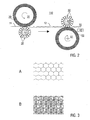
- the patterning layer 12 after the vaulting first the in FIG. 3A Having shown concave, hexagonal structure
- the plastic component 10 after post-structuring with the in FIG. 3B formed, three-dimensional facet structure formed.
- the three-dimensional facet structures are formed geometrically preferably in that in each case three support elements 50 converging to form a star point (in the view of FIG Fig. 2 not explicitly shown) against the concave side of a trough 2 or dome of the structured layer 12 press and trigger the secondary structuring.
- the in the FIGS. 3A and 3B shown hexagonal or three-dimensional facet-shaped structures have straight folds or webs. These folds or webs may according to a modified embodiment of the invention have a curved shape.
- FIG. 3A illustrates the top view of the vault-structured material web, where wrinkles are made visible as narrow lines.
- the beads of the three-dimensional wave-shaped structures a representation would result in which the lines are formed wider according to the wider-shaped support elements.
- the three-dimensional facets may alternatively be formed with beads (broad lines).
- the binder of the prepreg during the structuring passes with simultaneous curing from the rubber-elastic to the vitreous state (described in US Pat FIGS. 4 and 5 ).
- FIG. 4 shows schematically the viscosity of the binder in the prepreg as a function of the temperature, the reaction conversion and of the time, wherein the variables temperature and time are linked to the specific reaction conversion of the thermosetting prepreg.
- the viscosity decreases with increasing temperature. Only to the right of the vertical line, the viscosity increases steeply, because before reaching the gel point, the cross-linking of the molecules increases significantly.
- the prepreg is in the partially cured state before structuring, ie the curing state of the binder is located in front of the process window. The structuring with further curing takes place in the process window, where a transformation of the prepreg is advantageous.
- FIG. 5 schematically shows the modulus of elasticity of the structuring layer in the cured state.
- the modulus of elasticity decreases sharply. Therefore, the cured patterning layer behaves substantially "rubbery" at high temperatures (above the glass transition point).
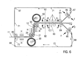
- FIG. 6 schematically shows a further embodiment of the inventive two-stage process for self-structuring a vault structure and a three-dimensional facet-shaped structure in a continuous manufacturing process.
- the supplied structuring layer prepreg 11
- the straps 71, 72 form support layers (see above, FIGS. 1D, E ) and are preferably made of thin metal strip, for example of a stainless steel strip with a thickness of about 0.1 mm.
- the layer structure of upper belt 71, structuring layer 11 and lower belt 72 is then fed to a first structuring unit, consisting of the support element roller 21 and the support elements 20 and the pressure roller 31 with the elastomer layer 30.
- a temperature control of the layer structure supply of heat with heaters H, in particular radiant heaters or inductive radiators may be provided to adjust the temperature of the prepreg in the desired process window.
- the reaction temperature can additionally be set reaction-specifically by the heated pressure element roller 21 and / or by the heating devices H.
- a three-dimensionally wave-shaped structure can be produced in the structuring layer, by additionally forming an elastomer layer (in FIG. 2) between the upper side of the structuring layer and the supporting elements 20 FIG. 6 not shown) or by providing the support elements 20 with such a contour are, as they would result from the self-structuring of the beads in the three-dimensional wave-like structuring.
- the structured patterning layer 12 of the post-structuring (secondary structuring) and the second structuring unit, consisting of the support element roller 51 and its support members 50 and the pressure roller 61 with the elastomer layer 60 is supplied.
- the prepreg is still in the process window, so that advantageously the further structuring can be complete and effective and the risk is reduced or eliminated that fibers break or the tight material composite dissolves.
- the arrangement of the patterning rollers 21 and 51 is selected such that a large angle of wrap occurs.
- the arrangement of the rollers 51 and 61 can also be chosen so that the structuring layer without further deflection, ie directed (analogous to FIG. 2 ), the structuring device leaves (in FIG. 6 not explicitly shown).
- tracking rollers adapted to the structure, chain links and / or elastomer bands, which are circulated and supported by rollers may be provided, as shown downstream of the second structuring unit.
- Pressure rollers 82 hold the composite with the structures 12.1 together, even if for the purpose of final curing nor heating energy to be supplied with a heater H from the outside.
- straightening rollers 83 With the help of straightening rollers 83, the almost cured structuring layer brought into the flatness.
- the upper belt 71 and the lower belt 72 are peeled (peeled off) from the cured patterning layer, deflected by means of deflection rollers 84 and smooth leveling rollers 85, 86, which press with a force F against the structured straps fed.
- the upper belt 71 are returned via the upper deflection rollers 87 and the lower belt 72 via the lower deflection rollers 88.
- a release layer of, for example, PP (polypropylene), PVF (polyvinyl fluoride), or an elastic layer on the top and bottom of the structuring layer may be carried through the process.
- the elastic separating layer can compensate for the possible residual unevenness of the smoothed straps in order to ensure a good surface of the structuring layer.
- the straps may be provided with a release agent.
- the embodiment of the in FIG. 6 shown two-stage process according to the invention can be modified so that the structuring takes place without the straps.
- the curing takes place with a first partial curing at the first structuring unit and a second partial curing at the second structuring unit, wherein in both cases the prepreg is in a state in the process window described above.
- the downstream pressure rollers, chain links or Elastomerb sections can be dispensed with. It is advantageous in this case, a small wrap angle or even the wrap angle of about zero.
- a 21 * 30 mm 2 prepreg was prepared from a fiber material and an unsaturated polyester.
- the Völb Modelltechniksrea, z. B. according to FIG. 1 applied.
- arch structures with a typical structure size of 33 mm were produced.
- the curing of the prepreg took place directly during or after the straightening of the vault-structured layer of the plastic component 10.
- the fiber material used was glass cloth with satin weave 1/7.
- the prepreg has an average thickness of about 0.3 mm.
- the prepreg was sandwiched between two release-treated aluminum sheets (AlMg3 and A199.5 - 0.3 mm thick, respectively) and then fed to the vatting patterning process. In this case, arch structures with 33 mm and 17 mm structure size were produced. Subsequently, the structured prepreg was thermally cured and the sheets removed. For Examples 2 to 5, modified cyanate resins were used.
- the fiber material used was fiberglass fabric of various grammage with satin weave 1/7.
- the resin content of the prepregs varied between 31-48%.
- flexural stiffnesses were determined by means of a 3-point bending test in comparison to flat reference layers (unstructured glass fiber reinforced structuring layers) of the same composition.
- the flexural stiffnesses of the vault-structured glass-fiber-reinforced structuring layers are larger by a factor of 4 to 5 than the flat reference layers.
- the fiber material used was fiberglass nonwovens of different basis weight.
- the resin content of the prepregs was between 50-60%.
- the prepregs had resin contents of about 40-60%.
- hemp fabrics of different basis weight were used.
- the resin content of the prepregs varied between 30-60%.
- the fiber material used were knits made of Nomex fibers with different basis weights.
- the prepregs had resin contents of 60-70%.
- Phenolic resin prepregs with Atlas weave 1/7 glass fiber fabric were used as the reinforcing material.
- the prepregs had resin contents of about 30-70%.
- a prepreg in the format 21 * 30 mm 2 with an average thickness of 0.3 mm was prepared. Thereafter, the prepreg was sandwiched between two release-treated aluminum sheets (AlMg3 and A199.5 - 0.3 mm thick, respectively) and then fed to the vatting patterning process. The curing of the prepregs took place immediately after or after straightening the vault-structured parts. Arch structures with 33 mm and 17 mm structure size were produced. For Example 1, modified cyanate resins were used.
- the fiber material used was fiberglass fabric of various grammage with satin weave 1/7.
- the fiber material used was fiberglass fabric of various grammage with satin weave 1/7.
Landscapes
- Engineering & Computer Science (AREA)
- Mechanical Engineering (AREA)
- Chemical & Material Sciences (AREA)
- Composite Materials (AREA)
- Laminated Bodies (AREA)
- Casting Or Compression Moulding Of Plastics Or The Like (AREA)
- Moulding By Coating Moulds (AREA)
- Reinforced Plastic Materials (AREA)
Claims (41)
- Procédé de fabrication d'un composant en plastique (10), comprenant les étapes consistant à :- mettre en place une couche de structuration (11, 12) entre des premiers éléments de support (20) et un premier élément de pression (30), et- gaufrer la couche de structuration (11, 12), le gaufrage de la couche de structuration (11, 12) comprenant les étapes consistant à :- supporter la couche de structuration (11, 12) sur une première surface (13) au moyen des premiers éléments de support (20), et- appliquer une pression à la couche de structuration (11, 12) sur la deuxième surface opposée (14) entre les premiers éléments de support (20), au moyen du premier élément de pression (30), de façon qu'il se forme dans la couche de structuration (11, 12), entre les premiers éléments de support (20), des gaufrures (2) d'une structure gaufrée formée par auto-organisation,
caractérisé en ce que- la couche de structuration (11, 12) contient une composition d'un matériau de renfort et d'un liant réticulable, et- il est prévu un durcissement de la couche de structuration (11, 12) pendant ou après le gaufrage. - Procédé selon la revendication 1, dans lequel la couche de structuration (12) est disposée après le gaufrage entre des deuxièmes éléments de support (50) et un deuxième élément de pression (60) et soumise à une post-structuration en appliquant une pression à la couche de structuration (12).
- Procédé selon la revendication 2, dans lequel la post-structuration se fait en sens inverse par rapport à celui du gaufrage précédent.
- Procédé selon l'une au moins des revendications précédentes, dans lequel le gaufrage et/ou la post-structuration se font en appliquant une pression avec auto-organisation à la couche de structuration (11, 12).
- Procédé selon l'une au moins des revendications 1 à 3, dans lequel les premiers ou deuxièmes éléments de support (20, 50) présentent une géométrie qui correspond à une structure gaufrée formée par auto-organisation et le gaufrage se fait en appliquant une pression avec formage de la couche de structuration (11, 12) par les premiers ou deuxièmes éléments de support (20, 50).
- Procédé selon la revendication 2, dans lequel le durcissement de la couche de structuration (12) est prévu pendant ou après la post-structuration.
- Procédé selon l'une au moins des revendications précédentes, dans lequel le durcissement se fait au moyen d'un traitement thermique et/ou radiochimique de la couche de structuration (11, 12).
- Procédé selon l'une au moins des revendications précédentes, dans lequel le durcissement comprend une transition de la composition du matériau de renfort et du liant d'un état caoutchoutique à un état vitreux.
- Procédé selon l'une au moins des revendications précédentes, dans lequel la mise en place de la couche de structuration (11) comprend un agencement exclusif de la couche de structuration (11) entre les premiers éléments de support (20) et le premier élément de pression (30).
- Procédé selon l'une au moins des revendications 1 à 7, dans lequel la mise en place de la couche de structuration (11) comprend un agencement d'une structure stratifiée (70) qui contient la couche de structuration (11) et au moins une couche support (71, 72) entre les premiers éléments de support (20) et le premier élément de pression (30), le gaufrage et/ou la post-structuration se faisant par l'application d'une pression avec auto-organisation à ladite au moins une couche support (71, 72) et/ou à la couche de structuration (11, 12).
- Procédé selon la revendication 10, dans lequel la structure stratifiée (70) comprend une première couche support (71), la couche de structuration (11) et une deuxième couche support (72).
- Procédé selon la revendication 10 ou la revendication 11, dans lequel ladite au moins une couche support comprend au moins une couche métallique et/ou au moins une feuille de matière plastique.
- Procédé selon la revendication 12, dans lequel la couche métallique comprend une tôle d'acier ou d'aluminium.
- Procédé selon la revendication 12 ou la revendication 13, dans lequel, pour le durcissement de la couche de structuration, il est prévu un chauffage inductif de ladite au moins une couche métallique.
- Procédé selon l'une au moins des revendications 10 à 14, dans lequel ladite au moins une couche support (71, 72) est percée de trous.
- Procédé selon l'une au moins des revendications 10 à 15, dans lequel un agent réduisant l'adhérence (73, 74) est déposé sur un côté au moins de la couche de structuration (11) ou de ladite au moins une couche support (71, 72).
- Procédé selon l'une au moins des revendications 10 à 16, dans lequel l'agencement de la structure stratifiée (70) comprend une jonction de bandes supérieures et inférieures (71, 72) formant les couches supports et de la couche de structuration (11).
- Procédé selon la revendication 17, dans lequel les bandes (71, 72) sont soumises à un lissage après le gaufrage ou la post- structuration et amenées à un processus continu d'agencement de la structure stratifiée (70).
- Procédé selon l'une au moins des revendications précédentes, dans lequel le matériau fibreux contient des fibres naturelles ou des fibres synthétiques.
- Procédé selon la revendication 19, dans lequel les fibres utilisées sont des fibres de cellulose, des fibres de verre, des fibres textiles et/ou des fibres de carbone.
- Procédé selon l'une au moins des revendications précédentes, dans lequel le matériau fibreux utilisé est constitué de demi-produits textiles plats.
- Procédé selon l'une au moins des revendications précédentes, dans lequel le liant réticulable utilisé est :(a) un polymère réticulable,(b) un prépolymère,(c) une combinaison d'un polymère réticulable ou d'un prépolymère avec un matériau thermoplastique,(d) une combinaison d'un polymère réticulable ou d'un prépolymère avec un matériau élastomère,(e) un composé contenant des groupes chimiquement réactifs, ou(f) une combinaison d'au moins deux liants suivant (a) à (e).
- Procédé selon la revendication 22, dans lequel le liant réticulable utilisé est au moins une substance choisie dans le groupe constitué par des résines phénoliques, des résines mélaminiques, des résines uréiques, des uréthanes, des isocyanates, des résines époxydiques, des acrylates, des polyesters insaturés, des polyesters, des esters vinyliques, des résines ou caoutchoucs de silicone, des résines à base de cyanates, des bismaléimides, des résines à base de maléimides, des benzoxazines, des perfluorocyclobutanes et des biscyclobutanes.
- Procédé selon l'une au moins des revendications précédentes, dans lequel le durcissement comprend une réaction de la couche de structuration pour donner un duroplastique ou un élastomère.
- Procédé selon l'une au moins des revendications précédentes, dans lequel une couche de structuration (15) multiplis est soumise au gaufrage.
- Procédé selon l'une au moins des revendications précédentes, dans lequel la couche de structuration (11, 12) comprend une bande continue de matériau et la mise en place et le gaufrage de la couche de structuration (11, 12) se font en continu, les premiers éléments de support (20) étant disposés sur la surface d'enveloppe d'un cylindre d'appui rotatif (21), tandis que le premier élément de pression (30) est formé par une surface d'enveloppe élastique d'un cylindre de pression (31), et la couche de structuration (11, 12) passant en vue du gaufrage entre le cylindre d'appui (21) et le cylindre de pression (31).
- Procédé selon l'une au moins des revendications précédentes, dans lequel une couche intermédiaire élastique est disposée entre la couche de structuration (11, 12) et l'un au moins des premiers ou deuxièmes éléments de support (20, 50) et des premiers ou deuxièmes éléments de pression (30, 60).
- Procédé selon l'une au moins des revendications précédentes, dans lequel la couche de structuration (11, 12) est soumise à une reprise qui comprend une opération au moins parmi un formage, une division, un assemblage avec une autre couche de structuration, un usinage des bords et un revêtement.
- Procédé selon l'une au moins des revendications précédentes, dans lequel la composition du matériau de renfort et du liant réticulable comprend un préimprégné.
- Composant en plastique qui présente une couche de structuration, avec une structure gaufrée de la couche de structuration formée par auto-organisation, caractérisé en ce que la couche de structuration comprend une composition d'un matériau de renfort et d'un liant réticulé.
- Composant en plastique selon la revendication 30, dans lequel le matériau de renfort comprend des fibres naturelles ou des fibres synthétiques.
- Composant en plastique selon la revendication 31, dans lequel le matériau fibreux comprend des fibres de cellulose, des fibres de verre, des fibres textiles et/ou des fibres de carbone.
- Composant en plastique selon l'une au moins des revendications 30 à 32, dans lequel le matériau fibreux comprend des semi-produits textiles plats.
- Composant en plastique selon l'une au moins des revendications 30 à 33, dans lequel le composant en plastique contient un duroplastique ou un élastomère.
- Composant en plastique selon l'une au moins des revendications 30 à 34, dans lequel la couche de structuration est à un seul pli.
- Composant en plastique selon l'une au moins des revendications 30 à 36, dans lequel la couche de structuration est multiplis.
- Composant en plastique selon la revendication 36, dans lequel la couche de structuration contient un polymère thermoplastique.
- Composant en plastique selon l'une au moins des revendications 30 à 37, qui présente une structure sandwich avec plusieurs couches de bandes continues de matériau superposées, seules une ou plusieurs couches centrales internes présentant une structure gaufrée.
- Composant en plastique selon la revendication 38, qui présente une structure composite faite de plusieurs matériaux différents.
- Composant en plastique selon la revendication 39, qui présente une structure composite à base de matière plastique et de métal.
- Utilisation d'un composant en plastique obtenu par un procédé selon l'une au moins des revendications 1 à 29 ou d'un composant en plastique selon l'une au moins des revendications 30 à 40 commue :- composant isolant acoustique,- cloison légère,- composant d'installation, en particulier pour des tuyaux ou des gaines,- composant thermostable destiné à être utilisé dans des conditions de contraintes thermiques alternées,- composant d'habillage de machines et de véhicules, en particulier d'aéronefs, de véhicules ferroviaires ou d'engins spatiaux,- composant absorbant les chocs, et/ou- élément d'aménagement, en particulier ayant un effet de réduction de l'éblouissement.
Applications Claiming Priority (1)
| Application Number | Priority Date | Filing Date | Title |
|---|---|---|---|
| DE200610014049 DE102006014049B4 (de) | 2006-03-27 | 2006-03-27 | Verfahren zur Herstellung eines strukturierten Kunststoffbauteils |
Publications (3)
| Publication Number | Publication Date |
|---|---|
| EP1839843A2 EP1839843A2 (fr) | 2007-10-03 |
| EP1839843A3 EP1839843A3 (fr) | 2008-08-27 |
| EP1839843B1 true EP1839843B1 (fr) | 2011-08-31 |
Family
ID=38219474
Family Applications (1)
| Application Number | Title | Priority Date | Filing Date |
|---|---|---|---|
| EP20070006314 Ceased EP1839843B1 (fr) | 2006-03-27 | 2007-03-27 | Procédé de fabrication d'un composant plastique structuré |
Country Status (2)
| Country | Link |
|---|---|
| EP (1) | EP1839843B1 (fr) |
| DE (1) | DE102006014049B4 (fr) |
Families Citing this family (11)
| Publication number | Priority date | Publication date | Assignee | Title |
|---|---|---|---|---|
| DE102009051603B4 (de) | 2009-11-02 | 2011-09-22 | Dr. Mirtsch Gmbh | Verfahren zum Herstellen eines strukturierten Rohres, nach dem Verfahren hergestelltes strukturiertes Erzeugnis und Verwendung desselben |
| DE102010042349B4 (de) * | 2010-10-12 | 2014-04-03 | Benteler Sgl Gmbh & Co. Kg | Textiles Halbzeug, insbesondere Prepreg, auf Basis von aus Recyclingfasern zusammengesetztem Carbonfaservlies, Verfahren zur Herstellung und Verwendung des textilen Halbzeugs sowie Carbonfaserverstärkter Verbundwerkstoff |
| DE102010034076B3 (de) | 2010-08-12 | 2011-12-22 | Dr. Mirtsch Gmbh | Verfahren zum Herstellen einer/ eines strukturierten, geraden oder ein- oder zweidimensional gekrümmten Materialbahn/ Profils, zugehörige/ zugehöriges dreidimensional strukturierte/ strukturiertes, gerade/ gerades oder ein- oder zweidimensional gekrümmte/ gekrümmtes Materialbahn/ Profil, Verwendung derselben und eine Vorrichtung zur Herstellung derselben |
| DE102011017353B4 (de) | 2011-04-16 | 2016-01-14 | Daimler Ag | Verfahren zur Herstellung einer Sandwichanordnung mit einer Kernlage und zumindest einer wölbstrukturierten Außenlage und Sandwichanordnung |
| DE102013017644B4 (de) * | 2012-10-25 | 2017-09-21 | Dr. Mirtsch Gmbh | Verfahren zum Herstellen einer mehrdimensional strukturierten Materialbahn und Verwendung derselben |
| DE102014000083B4 (de) | 2014-01-02 | 2017-12-07 | Dr. Mirtsch Gmbh | Verfahren zum Herstellen einer partiell dreidimensional wölbförmig strukturierten Materiaibahn, partiell dreidimensional wölbförmig strukturierte Materialbahn, Verwendung derselben und eine Vorrichtung zur Herstellung derselben |
| CN107253298B (zh) * | 2017-06-25 | 2019-06-18 | 青岛中集创赢复合材料科技有限公司 | 一种低孔隙率的连续纤维增强热塑性树脂预浸带的喷淋制备方法 |
| DE102019126825A1 (de) * | 2019-10-07 | 2021-04-08 | Lisa Dräxlmaier GmbH | Verfahren zum herstellen eines naturfaserverstärkten verkleidungsbauteils für ein kraftfahrzeug |
| WO2023280918A1 (fr) * | 2021-07-07 | 2023-01-12 | Papershell Ab | Matière fibreuse cellulosique et processus |
| EP4245561B1 (fr) * | 2022-03-14 | 2024-04-24 | PaperShell AB | Procédé de fabrication d'un article composite |
| EP4245491A1 (fr) * | 2022-03-14 | 2023-09-20 | PaperShell AB | Procédé de fabrication d'un article composite |
Family Cites Families (13)
| Publication number | Priority date | Publication date | Assignee | Title |
|---|---|---|---|---|
| US3575765A (en) * | 1963-04-04 | 1971-04-20 | Owens Corning Fiberglass Corp | Process of forming a synthetic resin panel |
| LU45437A1 (fr) * | 1963-12-17 | 1964-04-17 | ||
| US3717532A (en) | 1970-12-24 | 1973-02-20 | E Kamp | Method and apparatus for producing controllably oriented fibrous product |
| DE2706899A1 (de) * | 1977-02-17 | 1978-08-31 | Muanyagipari Kutato Intezet | Verfahren und vorrichtung zur herstellung von aus verstaerktem kunststoff angefertigten gewickelten formkoerpern mit sandwich-struktur |
| JPS5672931A (en) | 1979-11-20 | 1981-06-17 | Natl House Ind Co Ltd | Manufacture of die plate for resin with cubic pattern |
| DE4401974A1 (de) * | 1993-04-06 | 1995-07-27 | Frank Prof Dr Mirtsch | Verfahren und Vorrichtung zur Beulverformung |
| DE4437986A1 (de) * | 1994-10-24 | 1996-04-25 | Frank Dr Mirtsch | Verfahren zur Wölbstrukturierung dünner Wände und Folien |
| DE19611478A1 (de) * | 1996-03-23 | 1997-09-25 | Frank Prof Dr Mirtsch | Verfahren zur Erhöhung der Formfestigkeit dünner Materialbahnen |
| US6221299B1 (en) * | 1996-04-18 | 2001-04-24 | Frank Mirtsch | Structuring process that stiffens and protects the surface of thin material webs |
| DE19634244A1 (de) * | 1996-08-25 | 1998-02-26 | Frank Prof Dr Mirtsch | Verfahren zur Erhöhung der Formsteifigkeit beulstrukturierter Materialbahnen |
| DE10218144B4 (de) * | 2002-04-23 | 2007-10-04 | Dr. Mirtsch Gmbh | Strukturierter Behälter |
| DE10259591A1 (de) * | 2002-12-19 | 2004-07-15 | Daimlerchrysler Ag | Motorhaube mit Fußgängerschutz |
| DE102004031240A1 (de) * | 2003-08-26 | 2005-03-31 | Daimlerchrysler Ag | Wölbstrukturiertes Bauteil und Verfahren zu seiner Herstellung |
-
2006
- 2006-03-27 DE DE200610014049 patent/DE102006014049B4/de not_active Expired - Fee Related
-
2007
- 2007-03-27 EP EP20070006314 patent/EP1839843B1/fr not_active Ceased
Also Published As
| Publication number | Publication date |
|---|---|
| EP1839843A3 (fr) | 2008-08-27 |
| EP1839843A2 (fr) | 2007-10-03 |
| DE102006014049B4 (de) | 2009-06-04 |
| DE102006014049A1 (de) | 2007-10-11 |
Similar Documents
| Publication | Publication Date | Title |
|---|---|---|
| EP1839843B1 (fr) | Procédé de fabrication d'un composant plastique structuré | |
| EP2227379B1 (fr) | Procédé de production d'une ébauche en matériau composite renforcé par fibres à partir d'un stratifié comportant au moins deux couches préimprégnées et dispositif de production pour un procédé de ce type | |
| EP2938478B1 (fr) | Procédé et dispositif de production de nappes fibreuses tridimensionnelles et d'ébauches de pièces à partir de fibres en deux étapes | |
| DE102011012499B4 (de) | Vorrichtung und Verfahren zum Herstellen eines Faserverbundwerkstückes | |
| EP2637841A1 (fr) | Procédé et dispositif pour la fabrication d'une préforme tridimensionnelle dans le cadre de la fabrication d'éléments moulés renforcés de fibres | |
| EP2637842A1 (fr) | Procédé et dispositif pour la fabrication d'une préforme tridimensionnelle dans le cadre de la fabrication d'éléments moulés renforcés de fibres | |
| EP2185339A1 (fr) | Procede de fabrication d'un composant et composant thermoplastique renforce de fibres | |
| WO2011120717A1 (fr) | Procédé et dispositif pour réaliser une pièce structurale composite thermoplastique renforcée par fibres | |
| AT15268U1 (de) | Drapiervorrichtung zum Herstellen eines dreidimensionalen Vorformlings aus Fasermaterial | |
| DE10333161A1 (de) | Innenausstattungskomponenten von Kraftfahrzeugen mit einem definierten Oberflächenprofil | |
| DE4027092A1 (de) | Verfahren und vorrichtung zum biegen und formen eines flaechigen verbundwerkstoffs | |
| EP2418028B1 (fr) | Procédé de structuration pluridimensionnel d'une bande de matériau plate | |
| DE102016109284B3 (de) | Bogenförmige Faserverbundkunststoff-Preform und Verfahren zur Herstellung gekrümmter Profile | |
| EP2737987B1 (fr) | Procédé et dispositif de fabrication d'une pièce d'habillage intérieur | |
| WO2008055459A2 (fr) | Procédé de production d'un ressort à lames en un matériau composite fibreux avec une matière thermoplastique | |
| DE69810637T2 (de) | Verfahren zum formen eines lasttrageteils aus verstärktem thermoplast | |
| DE102019113067B3 (de) | Verfahren zur Herstellung eines flexibel formbaren Wabenkerns, Verwendung des Wabenkerns sowie Vorrichtung zur Durchführung des Verfahrens | |
| DE102008049359A1 (de) | Herstellungsverfahren für Hohlbauteile aus Faserverbundwerkstoffen in Schlauchbauweise, Folienschlauch und Herstellungsverfahren für einen Folienschlauch | |
| EP3560692B1 (fr) | Procédé de fabrication d'une préforme tridimensionnelle de fibres de renfort | |
| DE202013104091U1 (de) | Drapiervorrichtung zum Herstellen eines dreidimensionalen Vorformlings aus Fasermaterial | |
| WO2002094544A1 (fr) | Panneau composite a compartiments creux et procede de fabrication | |
| WO1996002389A1 (fr) | Procede et dispositif de production en continu de corps a couches multiples | |
| WO2021037405A1 (fr) | Dispositif et procédé pour la fabrication de préformes | |
| CH686820A5 (de) | Verfahren und Vorrichtung zur thermischen Verformung von Halbzeugen aus thermoformbaren Verbundwerkstoffen. | |
| DE102008008442A1 (de) | Verfahren zur Herstellung eines Bauteils |
Legal Events
| Date | Code | Title | Description |
|---|---|---|---|
| PUAI | Public reference made under article 153(3) epc to a published international application that has entered the european phase |
Free format text: ORIGINAL CODE: 0009012 |
|
| AK | Designated contracting states |
Kind code of ref document: A2 Designated state(s): AT BE BG CH CY CZ DE DK EE ES FI FR GB GR HU IE IS IT LI LT LU LV MC MT NL PL PT RO SE SI SK TR |
|
| AX | Request for extension of the european patent |
Extension state: AL BA HR MK YU |
|
| PUAL | Search report despatched |
Free format text: ORIGINAL CODE: 0009013 |
|
| AK | Designated contracting states |
Kind code of ref document: A3 Designated state(s): AT BE BG CH CY CZ DE DK EE ES FI FR GB GR HU IE IS IT LI LT LU LV MC MT NL PL PT RO SE SI SK TR |
|
| AX | Request for extension of the european patent |
Extension state: AL BA HR MK RS |
|
| RAP1 | Party data changed (applicant data changed or rights of an application transferred) |
Owner name: DR. MIRTSCH GMBHDE Owner name: INNOMAT GMBH |
|
| 17P | Request for examination filed |
Effective date: 20090116 |
|
| 17Q | First examination report despatched |
Effective date: 20090326 |
|
| AKX | Designation fees paid |
Designated state(s): DE FR GB |
|
| GRAP | Despatch of communication of intention to grant a patent |
Free format text: ORIGINAL CODE: EPIDOSNIGR1 |
|
| GRAS | Grant fee paid |
Free format text: ORIGINAL CODE: EPIDOSNIGR3 |
|
| REG | Reference to a national code |
Ref country code: DE Ref legal event code: R108 |
|
| RBV | Designated contracting states (corrected) |
Designated state(s): FR GB |
|
| GRAA | (expected) grant |
Free format text: ORIGINAL CODE: 0009210 |
|
| AK | Designated contracting states |
Kind code of ref document: B1 Designated state(s): FR GB |
|
| REG | Reference to a national code |
Ref country code: GB Ref legal event code: FG4D Free format text: NOT ENGLISH |
|
| REG | Reference to a national code |
Ref country code: DE Ref legal event code: R108 Effective date: 20110720 |
|
| PLBE | No opposition filed within time limit |
Free format text: ORIGINAL CODE: 0009261 |
|
| STAA | Information on the status of an ep patent application or granted ep patent |
Free format text: STATUS: NO OPPOSITION FILED WITHIN TIME LIMIT |
|
| 26N | No opposition filed |
Effective date: 20120601 |
|
| REG | Reference to a national code |
Ref country code: FR Ref legal event code: PLFP Year of fee payment: 10 |
|
| REG | Reference to a national code |
Ref country code: FR Ref legal event code: PLFP Year of fee payment: 11 |
|
| REG | Reference to a national code |
Ref country code: GB Ref legal event code: 732E Free format text: REGISTERED BETWEEN 20170427 AND 20170503 |
|
| REG | Reference to a national code |
Ref country code: FR Ref legal event code: PLFP Year of fee payment: 12 |
|
| PGFP | Annual fee paid to national office [announced via postgrant information from national office to epo] |
Ref country code: GB Payment date: 20190320 Year of fee payment: 13 Ref country code: FR Payment date: 20190322 Year of fee payment: 13 |
|
| PG25 | Lapsed in a contracting state [announced via postgrant information from national office to epo] |
Ref country code: FR Free format text: LAPSE BECAUSE OF NON-PAYMENT OF DUE FEES Effective date: 20200331 |
|
| GBPC | Gb: european patent ceased through non-payment of renewal fee |
Effective date: 20200327 |
|
| PG25 | Lapsed in a contracting state [announced via postgrant information from national office to epo] |
Ref country code: GB Free format text: LAPSE BECAUSE OF NON-PAYMENT OF DUE FEES Effective date: 20200327 |