EP1839932A2 - Système et procédé destinés à la sélection et au réglage de fonctions relatives au siège dans un véhicule automobile - Google Patents
Système et procédé destinés à la sélection et au réglage de fonctions relatives au siège dans un véhicule automobile Download PDFInfo
- Publication number
- EP1839932A2 EP1839932A2 EP07102325A EP07102325A EP1839932A2 EP 1839932 A2 EP1839932 A2 EP 1839932A2 EP 07102325 A EP07102325 A EP 07102325A EP 07102325 A EP07102325 A EP 07102325A EP 1839932 A2 EP1839932 A2 EP 1839932A2
- Authority
- EP
- European Patent Office
- Prior art keywords
- seat
- adjustment
- way switch
- switching elements
- switch
- Prior art date
- Legal status (The legal status is an assumption and is not a legal conclusion. Google has not performed a legal analysis and makes no representation as to the accuracy of the status listed.)
- Granted
Links
- 230000006870 function Effects 0.000 title claims abstract description 61
- 238000000034 method Methods 0.000 title claims abstract description 17
- 230000033001 locomotion Effects 0.000 claims description 19
- 230000008859 change Effects 0.000 claims description 13
- 125000004122 cyclic group Chemical group 0.000 claims description 10
- 125000000524 functional group Chemical group 0.000 claims description 8
- 230000003287 optical effect Effects 0.000 claims description 7
- 230000001419 dependent effect Effects 0.000 claims description 3
- 230000000007 visual effect Effects 0.000 claims description 3
- 241001422033 Thestylus Species 0.000 description 11
- 238000013016 damping Methods 0.000 description 8
- 239000006260 foam Substances 0.000 description 5
- 230000035699 permeability Effects 0.000 description 4
- 230000005540 biological transmission Effects 0.000 description 2
- 238000013461 design Methods 0.000 description 2
- 239000000463 material Substances 0.000 description 2
- 230000009467 reduction Effects 0.000 description 2
- 239000000725 suspension Substances 0.000 description 2
- 208000008035 Back Pain Diseases 0.000 description 1
- 206010049816 Muscle tightness Diseases 0.000 description 1
- 229910000831 Steel Inorganic materials 0.000 description 1
- ATJFFYVFTNAWJD-UHFFFAOYSA-N Tin Chemical compound [Sn] ATJFFYVFTNAWJD-UHFFFAOYSA-N 0.000 description 1
- 210000003484 anatomy Anatomy 0.000 description 1
- 210000001217 buttock Anatomy 0.000 description 1
- 238000012790 confirmation Methods 0.000 description 1
- 238000010276 construction Methods 0.000 description 1
- 238000001816 cooling Methods 0.000 description 1
- 230000001351 cycling effect Effects 0.000 description 1
- 238000011161 development Methods 0.000 description 1
- 238000005516 engineering process Methods 0.000 description 1
- 238000011156 evaluation Methods 0.000 description 1
- 230000004424 eye movement Effects 0.000 description 1
- 210000003811 finger Anatomy 0.000 description 1
- 238000010438 heat treatment Methods 0.000 description 1
- 239000010985 leather Substances 0.000 description 1
- 210000002414 leg Anatomy 0.000 description 1
- 239000002184 metal Substances 0.000 description 1
- 230000004048 modification Effects 0.000 description 1
- 238000012986 modification Methods 0.000 description 1
- 210000003205 muscle Anatomy 0.000 description 1
- 230000002265 prevention Effects 0.000 description 1
- 229910001285 shape-memory alloy Inorganic materials 0.000 description 1
- 239000010959 steel Substances 0.000 description 1
- 230000002123 temporal effect Effects 0.000 description 1
- 210000003813 thumb Anatomy 0.000 description 1
- 230000007704 transition Effects 0.000 description 1
- 238000002834 transmittance Methods 0.000 description 1
Images


Classifications
-
- B—PERFORMING OPERATIONS; TRANSPORTING
- B60—VEHICLES IN GENERAL
- B60N—SEATS SPECIALLY ADAPTED FOR VEHICLES; VEHICLE PASSENGER ACCOMMODATION NOT OTHERWISE PROVIDED FOR
- B60N2/00—Seats specially adapted for vehicles; Arrangement or mounting of seats in vehicles
- B60N2/64—Back-rests or cushions
- B60N2/66—Lumbar supports
- B60N2/665—Lumbar supports using inflatable bladders
-
- B—PERFORMING OPERATIONS; TRANSPORTING
- B60—VEHICLES IN GENERAL
- B60N—SEATS SPECIALLY ADAPTED FOR VEHICLES; VEHICLE PASSENGER ACCOMMODATION NOT OTHERWISE PROVIDED FOR
- B60N2/00—Seats specially adapted for vehicles; Arrangement or mounting of seats in vehicles
- B60N2/02—Seats specially adapted for vehicles; Arrangement or mounting of seats in vehicles the seat or part thereof being movable, e.g. adjustable
- B60N2/0224—Non-manual adjustments, e.g. with electrical operation
- B60N2/0226—User interfaces specially adapted for seat adjustment
- B60N2/0228—Hand-activated mechanical switches
-
- B—PERFORMING OPERATIONS; TRANSPORTING
- B60—VEHICLES IN GENERAL
- B60N—SEATS SPECIALLY ADAPTED FOR VEHICLES; VEHICLE PASSENGER ACCOMMODATION NOT OTHERWISE PROVIDED FOR
- B60N2/00—Seats specially adapted for vehicles; Arrangement or mounting of seats in vehicles
- B60N2/02—Seats specially adapted for vehicles; Arrangement or mounting of seats in vehicles the seat or part thereof being movable, e.g. adjustable
- B60N2/0224—Non-manual adjustments, e.g. with electrical operation
- B60N2/0226—User interfaces specially adapted for seat adjustment
- B60N2/0229—User interfaces specially adapted for seat adjustment characterised by the shape, e.g. switches having cushion or backrest shape
-
- B—PERFORMING OPERATIONS; TRANSPORTING
- B60—VEHICLES IN GENERAL
- B60N—SEATS SPECIALLY ADAPTED FOR VEHICLES; VEHICLE PASSENGER ACCOMMODATION NOT OTHERWISE PROVIDED FOR
- B60N2/00—Seats specially adapted for vehicles; Arrangement or mounting of seats in vehicles
- B60N2/90—Details or parts not otherwise provided for
- B60N2/914—Hydro-pneumatic adjustments of the shape
-
- B—PERFORMING OPERATIONS; TRANSPORTING
- B60—VEHICLES IN GENERAL
- B60N—SEATS SPECIALLY ADAPTED FOR VEHICLES; VEHICLE PASSENGER ACCOMMODATION NOT OTHERWISE PROVIDED FOR
- B60N2/00—Seats specially adapted for vehicles; Arrangement or mounting of seats in vehicles
- B60N2/90—Details or parts not otherwise provided for
- B60N2/986—Side-rests
- B60N2/99—Side-rests adjustable
-
- B—PERFORMING OPERATIONS; TRANSPORTING
- B60—VEHICLES IN GENERAL
- B60N—SEATS SPECIALLY ADAPTED FOR VEHICLES; VEHICLE PASSENGER ACCOMMODATION NOT OTHERWISE PROVIDED FOR
- B60N2210/00—Sensor types, e.g. for passenger detection systems or for controlling seats
- B60N2210/40—Force or pressure sensors
- B60N2210/44—Force or pressure sensors using fluids
Definitions
- the invention relates to a system and method for selecting and adjusting seat-related functions in a motor vehicle, in particular cars, for a vehicle seat with a frame, a support and a plurality of deformation elements between the frame and support.
- Transmissibility The most important factor determining the transmission of vibrations from the seat to the occupants is the "transmissibility" of the seat. Transmittance is defined as the ratio of the input vibrations (on the vehicle or seat frame) to the output vibrations on the seat cushion.
- Transmittance is defined as the ratio of the input vibrations (on the vehicle or seat frame) to the output vibrations on the seat cushion.
- the passive damping elements act as a filter between seat and vehicle to reduce high-frequency vibrations.
- so-called lower suspensions are used, which have a very good vibration damping with high surface elasticity.
- disadvantages are pressure peaks in the region of the ischial tuberosities and overshoots on bumpy roads. It is also known to insert a tin pan in the seat frame, on which a foam block rests. The foam block has a higher point elasticity than the former design, but attenuates the high-frequency vibrations from 5 Hz worse than the lower springs.
- the shape change elements allow by changing their shape z. B. adapt the seat contour to the occupant or set a massage function.
- Other technologies, such as shape memory alloys, electric actuators, etc. are also usable.
- the DE 100 63 478 A1 a seat for motor vehicles, which allows the use of multiple air cushion, the temporal change of the seat contour for massage.
- the air cushions are staggered with compressed air. A vibration damping or reduction of the permeability is not possible or not provided with this system.
- the air cushions are directly under the seat leg, so in the region that is already subjected to the highest seat pressures. Therefore, further pressure peaks are immediately perceived as unpleasant.
- the system uses only two air cushions below the seat cushion or the seat, so that only a pendulum motion can be generated, which allows only a left-right pelvic tilting. Such pelvic tipping, however, is undesirable from an anatomical point of view.
- This variety of deformation elements requires that such a seat also has a variety of seat-related functions, such as an adjustment of the seat contour, an adjustment of the lumbar support, a setting a lumbar support massage or an adjustment of a cyclic movement of the seat cushion.
- the 4-way switch on two substantially perpendicular to each other arranged actuating key pairs.
- the 4-way switch can additionally be designed to be rotatable about an axis perpendicular to the plane of the actuating keys, in order to switch over between different To make functional groups available.
- the 4-way switch has two actuating directions that are essentially perpendicular to one another.
- the 4-way switch can also be designed to be rotatable about an axis perpendicular to the direction of actuation, in order to provide a switch between different functional groups.
- the 4-way switch along the axis of rotation can be configured as a pressure switch to provide more functionalities available or to run.
- the 4-way switch employs an operating switch assembly integrated with a steering wheel with four switching elements arranged in a cross shape and with another switching element centrally located relative to the four switching elements, the four switching elements being cruciform are arranged around the central further switching element, wherein the switching elements are designed such that they are actuated separately from each other and that a further switching element, in particular annular, surrounding common rocker button is provided, via which the four switching elements are actuated separately.
- the further switching element can be made operable independently of the four switching elements via a separate button.
- the 4-way switch can also be arranged alternatively in the door or the seat.
- one or more switching elements may be fixedly assigned to the respective switching elements or the functions assigned to them may be freely programmable. Also, one or more switching elements may be configured such that the functions assigned to them change depending on the context.
- a means for optical and / or acoustic and / or tactile display of the selected function and its adjustment is provided. This allows an indication and / or confirmation of the selected function and / or the adjustment of the selected function.
- the optical display means is an indication of a navigation system, an on-board computer system, a driver information system or a dedicated display.
- the optical display can be a graphic display and / or a text display.
- the acoustic display means may be a speaker for voice reproduction.
- the means for tactile indication may be a pulsating change of the corresponding shape changing element.
- the display of the PDA then serves as an indicator and either the usual navigation key or a corresponding display on a touch display as the switch.
- the invention also relates to a corresponding method according to claim 22.
- the selection and adjustment of the seat-related functions via a 4-way switch in particular by selecting and adjusting the shape change elements.
- actuating key pairs or directions of actuation of a selection of the function to be adjusted via one of the substantially mutually perpendicular arranged actuating key pairs or directions of actuation of a selection of the function to be adjusted and on the other according to the adjustment of the functions.
- a particularly simple and intuitive operation is possible when switching between different functional groups via a rotation of the 4-way switch to an axis perpendicular to the plane of the actuating buttons or - directions axis.
- a switching between at least two function groups may be allowed to allow the hierarchical order of the user menu with a switch.
- the function groups can represent different operating states of the system, which are mutually exclusive because they are not simultaneously available due to the system. This applies, for example, to contour adjustment and massage mode.
- So z. B a selection of a function and the switching on and off of a massage function or a cyclic movement seat cushion or change the shape change elements allow.
- an optical and / or acoustic and / or tactile display of the selected function and its adjustment options and / or their adjustment can be made so that the user prompting is simplified.
- the operator receives feedback about the selected function and / or its adjustment.
- the feedback can be in optical form as a pictogram on a graphic display or as a list in text form on a text display. If the feedback occurs acoustically, this can be done as a voice over a loudspeaker. If the feedback occurs in tactile form, then the respective strain element can change its shape pulsating or vibrating, so that the user immediately notices which of the many strain elements he has selected.
- the above system is particularly suitable for carrying out this method.
- Fig. 1 shows schematically a designated as a whole with 1 inventive seat in an oblique perspective, the transparency allows a view into the interior of the seat.
- the seat 1 comprises a headrest 2, which is attached to the top of a backrest 3, which in turn is coupled via an adjustable hinge 5 with the actual seat 4.
- the seat 1 is supported by a frame 11 made of sheet steel, which is arranged under the actual seat and connected to the vehicle.
- the backrest 3 has a longitudinally section approximately S-shaped, anatomically shaped support 6 for the back of the occupant, which is bounded on the sides with projecting ribs 7, which give the occupant lateral support.
- the actual seat 4 also has a support 9, which defines the actual seat.
- protruding ribs 8 are provided on the sides, which provide lateral support to the occupant, in particular in curves.
- the support 9 is formed by a foam block 10 consisting of a suitable natural and / or plastic, which is optionally covered with a suitable material such as leather.
- the pad must have the usual and well-known properties, such as suspension, damping, moisture transport, etc. Furthermore, it is possible to provide heating and / or cooling devices in the support.
- a support plate 12 is provided below the foam block 10, a support plate 12 is provided made of rigid material.
- the support plate 12 is arranged below the rear region of the seat, where usually the buttocks of the occupant rests. For reasons of clarity, the support plate 12 is shown in Fig. 1 but not shown or transparent.
- a most significant feature of the seat of Figure 1 is the presence of four air bags 13 under the actual seat 9 between the support plate 12 and the frame 11.
- the air cushions are arranged such that they lie under the corners of the approximately rectangular seat.
- the four independently controllable and pressurizable air cushion 13 under the support plate 12 allow in addition to the vertical positioning tilting of the support plate 12 about two parallel to the plane of the seat and perpendicular to each other axes.
- a Beckenkippung can be generated in the direction from front to back and vice versa, which is relieving and z.
- B. is preferably used in spinal gymnastics. To avoid back pain, it is precisely this pelvic tilting that is important.
- These Movement can be coupled with a tilting movement from left to right, so that a particularly good prevention of fatigue is achieved by the conditional by the pelvic movement alternating cyclic arrival and relaxation of the muscles.
- the stroke of each air cushion is in the order of 5 mm and 30 mm, the larger stroke is used only for the height adjustment.
- An advantageous control cycle of the air cushion comprises a U-shaped course of the pressure wave or the application of the air cushion 13.
- the controller can automatically regulate the air pressure in the individual air bag 13 after evaluation of data from the driving situation and the occupants originating from sensors.
- the seat 1 in the ribs 7 and 8, the support 6 and the headrest 2 more air cushions 15, 17, 16 and 14, which serve for massage and contour adjustment. They can also be controlled and / or operated via the already mentioned control. Further, they may be inflated in case of impact of the vehicle and serve as an additional impact protection to prevent contact of the occupant with the metal frame 11 of the seat.
- the air bag (s) 14 in the headrest 2 can be changed in filling pressure to provide the occupant with a comfortable head support surface.
- the lateral airbags 15 and 17 can be changed in filling pressure to adjust the width of the seat or the lateral support in the seating area and back area as desired.
- a function is provided in which the airbags 15 and 17 of one side of the seat, namely the exit side, can be completely emptied to facilitate entry and exit.
- this is done by opening the corresponding door.
- the lumbar air bags 16 serve as a lumbar support and include upper, middle and lower members 16A, 16B and 16C. These can be adjusted in both the inflation pressure, as well as in the position and shape to provide a comfortable lumbar support to the occupant.
- a steering wheel 21 of a passenger car is shown in a plan view that has a circular ring gear 22 which is connected via four spokes 23 with a central portion 24.
- the steering wheel 21 is usually connected to the steering column and it usually houses an airbag.
- the ring gear 22 is encompassed by the fingers, with the palm rests on the steering wheel rim 22 so that the thumbs rest approximately on the upper spokes 23 in the region of the transition of the spokes 23 to the central part 24th
- Each switch assembly comprises a central switching element 27 and 28, which is actuated via a corresponding, visible in the figure button.
- the respective opposite switching elements 29,31 and 30,32 or 33,35 and 34,36 each form a pair of vertical and horizontal direction associated with opposite function, as will be described later. Their buttons are also marked with corresponding arrows.
- All switching elements are pressure switches and designed so that they can be actuated separately from each other. Furthermore, their keys have nubs that allow finding their pressure point without visual feedback.
- All switching elements are monitored by a microprocessor, not shown, so that their operating time is determined and depending on different functions per switching element executable.
- the microprocessor allows programming or modification of the function of the respective switching element, possibly also context-dependent.
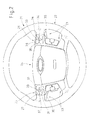
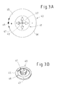
- FIGs. 3A and 3B an alternative 4-way switch 40 is shown, the z. B. at a suitable location on the door or center console, etc. can be arranged.
- the switch 40 comprises a joystick-like stylus 41 which, according to the scheme in Fig. 3A, is tiltable in directions perpendicular to each other 42, 43, as indicated by the arrows therein. Furthermore, the stylus 41 is one Rotatable perpendicular to these directions standing axis, as indicated by the arrow 44. In this case, the stylus 41 can be rotated in three positions 45, 46 and 47, in which it engages.
- the switch 40 is used for selecting and setting corresponding deformation elements, for.
- a movement of the stylus 41 in the direction 42 causes a cyclic passage through the individual deformation elements 13 to 17 (see below) and a movement of the stylus 41 in the direction 43 an adjustment of the momentary selected deformation element. This is indicated by the "+" and "-" signs in FIG. 3A.
- the switch 40 is used to turn on a lumbar support massage function, which is predetermined by the system and is optionally configured adjustable.
- the stylus 41 can be pressed along the axis of rotation 44 to store a selected setting.
- the right 4-way switch arrangement 26 of FIG. 2 is for controlling / operating a hierarchical menu for selecting and adjusting seat related functions, which is displayed on a display 50 of an otherwise unillustrated display and control apparatus motor vehicle related functions is displayed.
- the display 50 is arranged in the driver's field of vision, preferably in the center of the dashboard 51, between the speed and speed display.
- the driver is distracted as little as possible from the driving and must perform no major eye movements or head turns.
- the display can z. B. part of a conventional navigation / on-board computer system, in addition to the navigation via GPS, etc. also consumption values, range, outside temperature, current consumption, time, etc. displays and allows the control / setting of other functions of the vehicle.
- the system for displaying, selecting and adjusting seat related functions is controlled via the hierarchical menu 52.
- the menu comprises a basic menu I and several menu levels II, III, IV, each with a plurality of menu items II.1, II.2, II.3 ...; III.1, III.2, III.3 ..., IV.1, IV.2, IV.3 etc.
- the menu level IV contains a cyclic list of all the form-change elements or other seat-related functions to be traversed, which are indicated schematically by IV.1, IV.2, IV.3 and so on.
- the hierarchical menu 52 is controlled, set and actuated by means of a cursor 53, which in turn is moved by the switching elements of the switch arrangement 26.
- the cursor 53 is shown as a cross with an indication of the directions of movement.
- the vertical switching elements 33, 35 of the right switch assembly 26 are hard wired, d. H. assigned to a specific function regardless of the duration of the operation.
- this is the movement of the cursor through the one above the other Listed menu items (eg IV.1, IV.2, IV.3, etc.) of a menu level (here IV).
- the cursor arrives at a list above or below, it jumps down or up to the last or first displayed menu item. It thus moves intuitively cyclically through the displayed list in the direction of the respectively actuated key of a switching element, here 33, 35.
- the cursor 53 is located at the corresponding list position of a shape change element or the other function, these can be adjusted or switched on and off. Serve for this purpose, the horizontal switching elements 34, 36 and buttons.
- the filling pressure of the corresponding deformation element is lowered and increased accordingly by the switching element 36.
- the strain member becomes harder or softer.
- An actuation of the middle button 28 causes a storage of the current settings.
- a movement of the stylus 41 in the direction 42 in the case of the seat contour adjustment requires a cyclic passage through the individual deformation elements 13 to 17 to be adjusted (see below) and a movement of the stylus 41 in the direction 43 an adjustment of the currently selected deformation element.
- the switch 40 In the position of the lumbar support massage or the cyclic movement of the seat, the switch 40 is used to turn on.
- the stylus 41 can be pressed along the axis of rotation 44 to store a selected setting.
- the different functional groups can be displayed on the display 50 as different menu levels.
Landscapes
- Engineering & Computer Science (AREA)
- Aviation & Aerospace Engineering (AREA)
- Transportation (AREA)
- Mechanical Engineering (AREA)
- Human Computer Interaction (AREA)
- Seats For Vehicles (AREA)
Applications Claiming Priority (1)
| Application Number | Priority Date | Filing Date | Title |
|---|---|---|---|
| DE102006013968A DE102006013968A1 (de) | 2006-03-27 | 2006-03-27 | System und Verfahren zur Auswahl und Verstellung sitzbezogener Funktionen in einem Kraftfahrzeug |
Publications (3)
| Publication Number | Publication Date |
|---|---|
| EP1839932A2 true EP1839932A2 (fr) | 2007-10-03 |
| EP1839932A3 EP1839932A3 (fr) | 2008-04-02 |
| EP1839932B1 EP1839932B1 (fr) | 2010-12-22 |
Family
ID=38236544
Family Applications (1)
| Application Number | Title | Priority Date | Filing Date |
|---|---|---|---|
| EP07102325A Ceased EP1839932B1 (fr) | 2006-03-27 | 2007-02-14 | Systèmes et procédé destinés à la sélection et au réglage de fonctions relatives au siège dans un véhicule automobile |
Country Status (2)
| Country | Link |
|---|---|
| EP (1) | EP1839932B1 (fr) |
| DE (2) | DE102006013968A1 (fr) |
Cited By (32)
| Publication number | Priority date | Publication date | Assignee | Title |
|---|---|---|---|---|
| US20140032043A1 (en) * | 2012-07-27 | 2014-01-30 | Ford Global Technologies, Llc | Method and apparatus for controlling massage functions of a motor vehicle seat |
| US20150126916A1 (en) * | 2013-07-25 | 2015-05-07 | Ford Global Technologies, Llc | Flexible vehicle seat |
| US9630533B2 (en) | 2014-03-10 | 2017-04-25 | Ford Global Technologies, Llc | Switch for selecting and adjusting seat-related functions of motor vehicle seats |
| US9649962B2 (en) | 2013-01-24 | 2017-05-16 | Ford Global Technologies, Llc | Independent cushion extension and thigh support |
| US9663000B2 (en) | 2015-01-16 | 2017-05-30 | Ford Global Technologies, Llc | Vehicle seat configured to improve access |
| US9707870B2 (en) | 2013-01-24 | 2017-07-18 | Ford Global Technologies, Llc | Flexible seatback system |
| US9707873B2 (en) | 2013-01-24 | 2017-07-18 | Ford Global Technologies, Llc | Flexible seatback system |
| US9802512B1 (en) | 2016-04-12 | 2017-10-31 | Ford Global Technologies, Llc | Torsion spring bushing |
| US9834166B1 (en) | 2016-06-07 | 2017-12-05 | Ford Global Technologies, Llc | Side airbag energy management system |
| US9845029B1 (en) | 2016-06-06 | 2017-12-19 | Ford Global Technologies, Llc | Passive conformal seat with hybrid air/liquid cells |
| US9849817B2 (en) | 2016-03-16 | 2017-12-26 | Ford Global Technologies, Llc | Composite seat structure |
| US9849856B1 (en) | 2016-06-07 | 2017-12-26 | Ford Global Technologies, Llc | Side airbag energy management system |
| US9889773B2 (en) | 2016-04-04 | 2018-02-13 | Ford Global Technologies, Llc | Anthropomorphic upper seatback |
| US9914378B1 (en) | 2016-12-16 | 2018-03-13 | Ford Global Technologies, Llc | Decorative and functional upper seatback closeout assembly |
| US9994135B2 (en) | 2016-03-30 | 2018-06-12 | Ford Global Technologies, Llc | Independent cushion thigh support |
| US10046683B2 (en) | 2014-01-23 | 2018-08-14 | Ford Global Technologies, Llc | Suspension seat back and cushion system having an inner suspension panel |
| US10046682B2 (en) | 2015-08-03 | 2018-08-14 | Ford Global Technologies, Llc | Back cushion module for a vehicle seating assembly |
| US10065546B2 (en) | 2014-04-02 | 2018-09-04 | Ford Global Technologies, Llc | Vehicle seating assembly with manual independent thigh supports |
| US10166895B2 (en) | 2016-06-09 | 2019-01-01 | Ford Global Technologies, Llc | Seatback comfort carrier |
| US10166894B2 (en) | 2016-06-09 | 2019-01-01 | Ford Global Technologies, Llc | Seatback comfort carrier |
| US10220737B2 (en) | 2016-04-01 | 2019-03-05 | Ford Global Technologies, Llc | Kinematic back panel |
| US10239431B2 (en) | 2016-09-02 | 2019-03-26 | Ford Global Technologies, Llc | Cross-tube attachment hook features for modular assembly and support |
| US10279714B2 (en) | 2016-08-26 | 2019-05-07 | Ford Global Technologies, Llc | Seating assembly with climate control features |
| US10286824B2 (en) | 2016-08-24 | 2019-05-14 | Ford Global Technologies, Llc | Spreader plate load distribution |
| US10286825B2 (en) | 2016-09-08 | 2019-05-14 | Ford Global Technologies, Llc | Support assembly for a vehicle seat |
| US10286818B2 (en) | 2016-03-16 | 2019-05-14 | Ford Global Technologies, Llc | Dual suspension seating assembly |
| US10369905B2 (en) | 2014-10-03 | 2019-08-06 | Ford Global Technologies, Llc | Tuned flexible support member and flexible suspension features for comfort carriers |
| US10377279B2 (en) | 2016-06-09 | 2019-08-13 | Ford Global Technologies, Llc | Integrated decking arm support feature |
| US10391910B2 (en) | 2016-09-02 | 2019-08-27 | Ford Global Technologies, Llc | Modular assembly cross-tube attachment tab designs and functions |
| US10596936B2 (en) | 2017-05-04 | 2020-03-24 | Ford Global Technologies, Llc | Self-retaining elastic strap for vent blower attachment to a back carrier |
| JP2020083175A (ja) * | 2018-11-29 | 2020-06-04 | トヨタ紡織株式会社 | 手動バルブ装置 |
| JP2020083176A (ja) * | 2018-11-29 | 2020-06-04 | トヨタ紡織株式会社 | 手動バルブ装置 |
Families Citing this family (8)
| Publication number | Priority date | Publication date | Assignee | Title |
|---|---|---|---|---|
| DE102012212834A1 (de) | 2012-07-23 | 2014-01-23 | Ford Global Technologies, Llc | Verfahren zur Steuerung und Auswahl von Massagefunktionen eines Kraftfahrzeugsitzes |
| DE102012224449A1 (de) * | 2012-12-27 | 2014-07-03 | Robert Bosch Gmbh | Sitzvorrichtung |
| DE102014205576B4 (de) | 2014-03-26 | 2016-11-03 | Ford Global Technologies, Llc | System und Verfahren zur Steuerung und Auswahl von Massagefunktionen eines Kraftfahrzeugsitzes |
| DE102014205574A1 (de) | 2014-03-26 | 2015-10-01 | Ford Global Technologies, Llc | System zur Steuerung und Auswahl von Massagefunktionen eines Kraftfahrzeugsitzes |
| DE102015218051A1 (de) | 2015-09-21 | 2017-03-23 | Volkswagen Aktiengesellschaft | Verfahren und ein System zum Steuern der Bewegung zumindest eines elektromechanischen Bauteils, insbesondere in einem Fahrzeug |
| DE102017001754A1 (de) | 2017-02-23 | 2017-08-17 | Daimler Ag | Sitzanpassungsanordnung für einen Fahrzeugsitz |
| DE102019114822A1 (de) * | 2019-06-03 | 2020-12-03 | Dr. Ing. H.C. F. Porsche Aktiengesellschaft | Innenverkleidungsanordnung und Verfahren zur seitlichen Stabilisierung eines Beins |
| DE102021004332A1 (de) | 2021-08-24 | 2023-03-02 | Mercedes-Benz Group AG | Gestaltungsvorrichtung für ein Fahrzeug und Verfahren zur variablen Gestaltung |
Family Cites Families (5)
| Publication number | Priority date | Publication date | Assignee | Title |
|---|---|---|---|---|
| US6203105B1 (en) * | 1999-08-20 | 2001-03-20 | Mccord Winn Textron Inc. | Vehicle impact responsive multiple bladder seating and headrest system and method |
| NO20005119L (no) * | 2000-02-18 | 2001-08-20 | Ziad Badarneh | Interaktivt system |
| DE10063478A1 (de) * | 2000-12-20 | 2002-07-04 | Alfmeier Praez Ag | Sitz, insbesondere Fahrzeugsitz |
| DE20212142U1 (de) * | 2002-08-07 | 2003-10-23 | Brose Fahrzeugteile GmbH & Co. Kommanditgesellschaft, Coburg, 96450 Coburg | Steuerungsvorrichtung einer Lordosenverstelleinrichtung eines Kraftfahrzeugs |
| EP1564066B1 (fr) * | 2004-02-13 | 2007-08-22 | Ford Global Technologies, LLC, A subsidary of Ford Motor Company | Siège |
-
2006
- 2006-03-27 DE DE102006013968A patent/DE102006013968A1/de not_active Ceased
-
2007
- 2007-02-14 EP EP07102325A patent/EP1839932B1/fr not_active Ceased
- 2007-02-14 DE DE502007005999T patent/DE502007005999D1/de active Active
Cited By (39)
| Publication number | Priority date | Publication date | Assignee | Title |
|---|---|---|---|---|
| CN103568903A (zh) * | 2012-07-27 | 2014-02-12 | 福特全球技术公司 | 用于选择和控制机动车辆座椅的按摩功能的方法 |
| US20140032043A1 (en) * | 2012-07-27 | 2014-01-30 | Ford Global Technologies, Llc | Method and apparatus for controlling massage functions of a motor vehicle seat |
| US9707870B2 (en) | 2013-01-24 | 2017-07-18 | Ford Global Technologies, Llc | Flexible seatback system |
| US9873360B2 (en) | 2013-01-24 | 2018-01-23 | Ford Global Technologies, Llc | Flexible seatback system |
| US9873362B2 (en) | 2013-01-24 | 2018-01-23 | Ford Global Technologies, Llc | Flexible seatback system |
| US9707873B2 (en) | 2013-01-24 | 2017-07-18 | Ford Global Technologies, Llc | Flexible seatback system |
| US9649962B2 (en) | 2013-01-24 | 2017-05-16 | Ford Global Technologies, Llc | Independent cushion extension and thigh support |
| US9579998B2 (en) | 2013-07-25 | 2017-02-28 | Ford Global Technologies, Llc | Flexible vehicle seat |
| US20150126916A1 (en) * | 2013-07-25 | 2015-05-07 | Ford Global Technologies, Llc | Flexible vehicle seat |
| US10046683B2 (en) | 2014-01-23 | 2018-08-14 | Ford Global Technologies, Llc | Suspension seat back and cushion system having an inner suspension panel |
| US9630533B2 (en) | 2014-03-10 | 2017-04-25 | Ford Global Technologies, Llc | Switch for selecting and adjusting seat-related functions of motor vehicle seats |
| US10065546B2 (en) | 2014-04-02 | 2018-09-04 | Ford Global Technologies, Llc | Vehicle seating assembly with manual independent thigh supports |
| US10369905B2 (en) | 2014-10-03 | 2019-08-06 | Ford Global Technologies, Llc | Tuned flexible support member and flexible suspension features for comfort carriers |
| US9663000B2 (en) | 2015-01-16 | 2017-05-30 | Ford Global Technologies, Llc | Vehicle seat configured to improve access |
| CN105799566A (zh) * | 2015-01-16 | 2016-07-27 | 福特全球技术公司 | 柔性车辆座椅 |
| CN105799566B (zh) * | 2015-01-16 | 2020-07-14 | 福特全球技术公司 | 柔性车辆座椅 |
| US10046682B2 (en) | 2015-08-03 | 2018-08-14 | Ford Global Technologies, Llc | Back cushion module for a vehicle seating assembly |
| US9849817B2 (en) | 2016-03-16 | 2017-12-26 | Ford Global Technologies, Llc | Composite seat structure |
| US10286818B2 (en) | 2016-03-16 | 2019-05-14 | Ford Global Technologies, Llc | Dual suspension seating assembly |
| US9994135B2 (en) | 2016-03-30 | 2018-06-12 | Ford Global Technologies, Llc | Independent cushion thigh support |
| US10220737B2 (en) | 2016-04-01 | 2019-03-05 | Ford Global Technologies, Llc | Kinematic back panel |
| US9889773B2 (en) | 2016-04-04 | 2018-02-13 | Ford Global Technologies, Llc | Anthropomorphic upper seatback |
| US9802512B1 (en) | 2016-04-12 | 2017-10-31 | Ford Global Technologies, Llc | Torsion spring bushing |
| US9845029B1 (en) | 2016-06-06 | 2017-12-19 | Ford Global Technologies, Llc | Passive conformal seat with hybrid air/liquid cells |
| US9834166B1 (en) | 2016-06-07 | 2017-12-05 | Ford Global Technologies, Llc | Side airbag energy management system |
| US9849856B1 (en) | 2016-06-07 | 2017-12-26 | Ford Global Technologies, Llc | Side airbag energy management system |
| US10166895B2 (en) | 2016-06-09 | 2019-01-01 | Ford Global Technologies, Llc | Seatback comfort carrier |
| US10377279B2 (en) | 2016-06-09 | 2019-08-13 | Ford Global Technologies, Llc | Integrated decking arm support feature |
| US10166894B2 (en) | 2016-06-09 | 2019-01-01 | Ford Global Technologies, Llc | Seatback comfort carrier |
| US10286824B2 (en) | 2016-08-24 | 2019-05-14 | Ford Global Technologies, Llc | Spreader plate load distribution |
| US10279714B2 (en) | 2016-08-26 | 2019-05-07 | Ford Global Technologies, Llc | Seating assembly with climate control features |
| US10239431B2 (en) | 2016-09-02 | 2019-03-26 | Ford Global Technologies, Llc | Cross-tube attachment hook features for modular assembly and support |
| US10391910B2 (en) | 2016-09-02 | 2019-08-27 | Ford Global Technologies, Llc | Modular assembly cross-tube attachment tab designs and functions |
| US10286825B2 (en) | 2016-09-08 | 2019-05-14 | Ford Global Technologies, Llc | Support assembly for a vehicle seat |
| US9914378B1 (en) | 2016-12-16 | 2018-03-13 | Ford Global Technologies, Llc | Decorative and functional upper seatback closeout assembly |
| US10596936B2 (en) | 2017-05-04 | 2020-03-24 | Ford Global Technologies, Llc | Self-retaining elastic strap for vent blower attachment to a back carrier |
| JP2020083175A (ja) * | 2018-11-29 | 2020-06-04 | トヨタ紡織株式会社 | 手動バルブ装置 |
| JP2020083176A (ja) * | 2018-11-29 | 2020-06-04 | トヨタ紡織株式会社 | 手動バルブ装置 |
| US11420545B2 (en) | 2018-11-29 | 2022-08-23 | Toyota Boshoku Kabushiki Kaisha | Manual valve device |
Also Published As
| Publication number | Publication date |
|---|---|
| EP1839932A3 (fr) | 2008-04-02 |
| DE502007005999D1 (de) | 2011-02-03 |
| DE102006013968A1 (de) | 2007-10-18 |
| EP1839932B1 (fr) | 2010-12-22 |
Similar Documents
| Publication | Publication Date | Title |
|---|---|---|
| EP1839932B1 (fr) | Systèmes et procédé destinés à la sélection et au réglage de fonctions relatives au siège dans un véhicule automobile | |
| DE102014204321A1 (de) | Schalter zur Auswahl und Verstellung von sitzbezogenen Funktionen von Kraftfahrzeugsitzen | |
| DE102012213285A1 (de) | Verfahren zur Auswahl und Steuerung von Massagefunktionen eines Kraftfahrzeugsitzes | |
| DE102016100325A1 (de) | Flexibler Fahrzeugsitz | |
| EP1592575B1 (fr) | Element d'equipement interieur pour vehicule et procede de production correspondant | |
| EP3594053B1 (fr) | Siège de véhicule pourvu d'un dispositif de commande | |
| DE102012021519B4 (de) | Lüftungssystem für ein Kraftfahrzeug sowie Verfahren zum Betreiben eines solchen | |
| EP3694749B1 (fr) | Procédé de commande de fonctions de véhicule | |
| DE102017206313B4 (de) | Verfahren zur Sitzverstellung eines Verkehrsmittels | |
| EP3022083B1 (fr) | Siège de véhicule pour véhicule automobile | |
| DE102016103017B4 (de) | Fahrzeugsitz | |
| DE102014205574A1 (de) | System zur Steuerung und Auswahl von Massagefunktionen eines Kraftfahrzeugsitzes | |
| DE102012212834A1 (de) | Verfahren zur Steuerung und Auswahl von Massagefunktionen eines Kraftfahrzeugsitzes | |
| DE102010062317B4 (de) | Positioniervorrichtung für einen Fahrzeugsitz, Verfahren zum Positionieren eines Fahrzeugsitzes und Fahrzeugsitz | |
| EP1712405B1 (fr) | Siège, en particulier siège de véhicule | |
| DE102017216410A1 (de) | Verfahren zur Steuerung der Massagefunktion eines Sitzes | |
| EP3608163B1 (fr) | Siège de véhicule pourvu de dispositif de commande | |
| DE10242113B4 (de) | Vorrichtung zur Erkennung einer Sitzposition eines Insassen in einem Fahrzeug | |
| EP1564066B1 (fr) | Siège | |
| DE19922409A1 (de) | Bedienanordnung zur Sitzeinstellung bei Kraftfahrzeugen | |
| DE102014205576B4 (de) | System und Verfahren zur Steuerung und Auswahl von Massagefunktionen eines Kraftfahrzeugsitzes | |
| DE102014204322A1 (de) | Schalter zur Auswahl und Verstellung von sitzbezogenen Funktionen von Kraftfahrzeugsitzen | |
| DE102020111367A1 (de) | Verfahren zur Steuerung und zur Regelung einer adaptiven Stützvorrichtung für Insassen eines Kraftfahrzeugs, sowie Bedienvorrichtung, adaptives Stützsystem und Kraftfahrzeug | |
| DE102013019896B4 (de) | Kraftfahrzeug mit motorisch verstellbarem Funktionselement und Verfahren zum Betreiben eines Kraftfahrzeugs | |
| DE19943998C2 (de) | Multifunktionaler Fahrzeugsitz |
Legal Events
| Date | Code | Title | Description |
|---|---|---|---|
| PUAI | Public reference made under article 153(3) epc to a published international application that has entered the european phase |
Free format text: ORIGINAL CODE: 0009012 |
|
| AK | Designated contracting states |
Kind code of ref document: A2 Designated state(s): AT BE BG CH CY CZ DE DK EE ES FI FR GB GR HU IE IS IT LI LT LU LV MC NL PL PT RO SE SI SK TR |
|
| AX | Request for extension of the european patent |
Extension state: AL BA HR MK YU |
|
| PUAL | Search report despatched |
Free format text: ORIGINAL CODE: 0009013 |
|
| AK | Designated contracting states |
Kind code of ref document: A3 Designated state(s): AT BE BG CH CY CZ DE DK EE ES FI FR GB GR HU IE IS IT LI LT LU LV MC NL PL PT RO SE SI SK TR |
|
| AX | Request for extension of the european patent |
Extension state: AL BA HR MK YU |
|
| 17P | Request for examination filed |
Effective date: 20081002 |
|
| 17Q | First examination report despatched |
Effective date: 20081103 |
|
| AKX | Designation fees paid |
Designated state(s): DE FR GB |
|
| RTI1 | Title (correction) |
Free format text: SYSTEMS AND METHOD FOR SELECTION AND ADJUSTMENT OF SEAT RELATED FUNCTIONS IN A MOTOR VEHICLE |
|
| GRAP | Despatch of communication of intention to grant a patent |
Free format text: ORIGINAL CODE: EPIDOSNIGR1 |
|
| GRAS | Grant fee paid |
Free format text: ORIGINAL CODE: EPIDOSNIGR3 |
|
| GRAA | (expected) grant |
Free format text: ORIGINAL CODE: 0009210 |
|
| AK | Designated contracting states |
Kind code of ref document: B1 Designated state(s): DE FR GB |
|
| REG | Reference to a national code |
Ref country code: GB Ref legal event code: FG4D Free format text: NOT ENGLISH |
|
| REF | Corresponds to: |
Ref document number: 502007005999 Country of ref document: DE Date of ref document: 20110203 Kind code of ref document: P |
|
| REG | Reference to a national code |
Ref country code: DE Ref legal event code: R096 Ref document number: 502007005999 Country of ref document: DE Effective date: 20110203 |
|
| PLBE | No opposition filed within time limit |
Free format text: ORIGINAL CODE: 0009261 |
|
| STAA | Information on the status of an ep patent application or granted ep patent |
Free format text: STATUS: NO OPPOSITION FILED WITHIN TIME LIMIT |
|
| 26N | No opposition filed |
Effective date: 20110923 |
|
| REG | Reference to a national code |
Ref country code: DE Ref legal event code: R097 Ref document number: 502007005999 Country of ref document: DE Effective date: 20110923 |
|
| REG | Reference to a national code |
Ref country code: FR Ref legal event code: PLFP Year of fee payment: 10 |
|
| REG | Reference to a national code |
Ref country code: FR Ref legal event code: PLFP Year of fee payment: 11 |
|
| REG | Reference to a national code |
Ref country code: FR Ref legal event code: PLFP Year of fee payment: 12 |
|
| PGFP | Annual fee paid to national office [announced via postgrant information from national office to epo] |
Ref country code: GB Payment date: 20190128 Year of fee payment: 13 Ref country code: DE Payment date: 20190115 Year of fee payment: 13 Ref country code: FR Payment date: 20190117 Year of fee payment: 13 |
|
| PGFP | Annual fee paid to national office [announced via postgrant information from national office to epo] |
Ref country code: DE Payment date: 20190115 Year of fee payment: 13 |
|
| REG | Reference to a national code |
Ref country code: DE Ref legal event code: R119 Ref document number: 502007005999 Country of ref document: DE |
|
| GBPC | Gb: european patent ceased through non-payment of renewal fee |
Effective date: 20200214 |
|
| PG25 | Lapsed in a contracting state [announced via postgrant information from national office to epo] |
Ref country code: FR Free format text: LAPSE BECAUSE OF NON-PAYMENT OF DUE FEES Effective date: 20200229 Ref country code: DE Free format text: LAPSE BECAUSE OF NON-PAYMENT OF DUE FEES Effective date: 20200901 Ref country code: GB Free format text: LAPSE BECAUSE OF NON-PAYMENT OF DUE FEES Effective date: 20200214 |