EP1839955B1 - Verkleidungsanordnung zwischen zwei Teilen für ein Fahrerhaus eines Kraftfahrzeugs - Google Patents
Verkleidungsanordnung zwischen zwei Teilen für ein Fahrerhaus eines Kraftfahrzeugs Download PDFInfo
- Publication number
- EP1839955B1 EP1839955B1 EP07300892A EP07300892A EP1839955B1 EP 1839955 B1 EP1839955 B1 EP 1839955B1 EP 07300892 A EP07300892 A EP 07300892A EP 07300892 A EP07300892 A EP 07300892A EP 1839955 B1 EP1839955 B1 EP 1839955B1
- Authority
- EP
- European Patent Office
- Prior art keywords
- tab
- piece
- main surface
- arrangement according
- ribs
- Prior art date
- Legal status (The legal status is an assumption and is not a legal conclusion. Google has not performed a legal analysis and makes no representation as to the accuracy of the status listed.)
- Not-in-force
Links
- 229920000642 polymer Polymers 0.000 claims abstract description 18
- 239000000463 material Substances 0.000 claims description 12
- 230000000295 complement effect Effects 0.000 claims description 7
- 238000007688 edging Methods 0.000 claims 7
- 238000003780 insertion Methods 0.000 description 5
- 230000037431 insertion Effects 0.000 description 5
- 238000005253 cladding Methods 0.000 description 4
- 238000007747 plating Methods 0.000 description 4
- 239000006260 foam Substances 0.000 description 3
- 239000002184 metal Substances 0.000 description 3
- 230000012010 growth Effects 0.000 description 2
- 238000004519 manufacturing process Methods 0.000 description 2
- -1 polyethylenes Polymers 0.000 description 2
- 239000004698 Polyethylene Substances 0.000 description 1
- 239000004743 Polypropylene Substances 0.000 description 1
- 230000006978 adaptation Effects 0.000 description 1
- 238000005452 bending Methods 0.000 description 1
- 230000000903 blocking effect Effects 0.000 description 1
- 239000000470 constituent Substances 0.000 description 1
- 239000004744 fabric Substances 0.000 description 1
- 238000012986 modification Methods 0.000 description 1
- 230000004048 modification Effects 0.000 description 1
- 239000004033 plastic Substances 0.000 description 1
- 229920003023 plastic Polymers 0.000 description 1
- 229920000573 polyethylene Polymers 0.000 description 1
- 239000002861 polymer material Substances 0.000 description 1
- 229920001155 polypropylene Polymers 0.000 description 1
- 230000035807 sensation Effects 0.000 description 1
- 238000009491 slugging Methods 0.000 description 1
- 230000000007 visual effect Effects 0.000 description 1
- 239000002023 wood Substances 0.000 description 1
Images
Classifications
-
- B—PERFORMING OPERATIONS; TRANSPORTING
- B60—VEHICLES IN GENERAL
- B60R—VEHICLES, VEHICLE FITTINGS, OR VEHICLE PARTS, NOT OTHERWISE PROVIDED FOR
- B60R13/00—Elements for body-finishing, identifying, or decorating; Arrangements or adaptations for advertising purposes
- B60R13/02—Internal Trim mouldings ; Internal Ledges; Wall liners for passenger compartments; Roof liners
-
- B—PERFORMING OPERATIONS; TRANSPORTING
- B60—VEHICLES IN GENERAL
- B60N—SEATS SPECIALLY ADAPTED FOR VEHICLES; VEHICLE PASSENGER ACCOMMODATION NOT OTHERWISE PROVIDED FOR
- B60N2/00—Seats specially adapted for vehicles; Arrangement or mounting of seats in vehicles
- B60N2/02—Seats specially adapted for vehicles; Arrangement or mounting of seats in vehicles the seat or part thereof being movable, e.g. adjustable
- B60N2/22—Seats specially adapted for vehicles; Arrangement or mounting of seats in vehicles the seat or part thereof being movable, e.g. adjustable the back-rest being adjustable
-
- B—PERFORMING OPERATIONS; TRANSPORTING
- B60—VEHICLES IN GENERAL
- B60N—SEATS SPECIALLY ADAPTED FOR VEHICLES; VEHICLE PASSENGER ACCOMMODATION NOT OTHERWISE PROVIDED FOR
- B60N2/00—Seats specially adapted for vehicles; Arrangement or mounting of seats in vehicles
- B60N2/64—Back-rests or cushions
- B60N2/643—Back-rests or cushions shape of the back-rests
-
- B—PERFORMING OPERATIONS; TRANSPORTING
- B60—VEHICLES IN GENERAL
- B60R—VEHICLES, VEHICLE FITTINGS, OR VEHICLE PARTS, NOT OTHERWISE PROVIDED FOR
- B60R13/00—Elements for body-finishing, identifying, or decorating; Arrangements or adaptations for advertising purposes
- B60R13/02—Internal Trim mouldings ; Internal Ledges; Wall liners for passenger compartments; Roof liners
- B60R2013/0281—Internal Trim mouldings ; Internal Ledges; Wall liners for passenger compartments; Roof liners made of a plurality of visible parts
-
- B—PERFORMING OPERATIONS; TRANSPORTING
- B60—VEHICLES IN GENERAL
- B60R—VEHICLES, VEHICLE FITTINGS, OR VEHICLE PARTS, NOT OTHERWISE PROVIDED FOR
- B60R13/00—Elements for body-finishing, identifying, or decorating; Arrangements or adaptations for advertising purposes
- B60R13/02—Internal Trim mouldings ; Internal Ledges; Wall liners for passenger compartments; Roof liners
- B60R2013/0293—Connection or positioning of adjacent panels
Definitions
- the present invention relates to a cladding arrangement comprising a first part, for example a flexible material of the carpet type, and a second part, for example a rigid material of the polymer type.
- the invention also relates to such a cladding arrangement more specifically intended to cover part of a passenger compartment of a motor vehicle.
- a motor vehicle includes a cabin whose interior is made of many different materials.
- the metal parts are progressively replaced by parts made of plastic or polymer materials, for example polyethylenes and / or polypropylenes.
- materials to generate visual and tactile sensations particularly pleasant were added, such as wood, fabrics and / or carpets. These materials are intended to hide the constituent plate of the vehicle body and form an environment that absorbs engine noise and retains heat.
- a quality of finish for his vehicle.
- a finish is also related to the quality and durability of the connection between a sheet of a flexible material, such as a carpet, and a plate of a rigid material, such as a polymer.
- the connection between a first piece of carpet and a second piece of polymer must withstand tensile stresses in the plane. Moreover, such fastening must be easily and very quickly achievable by the operators during the manufacture of the vehicle.
- a first solution is to add blocks of foam. These foams are stuck or stuck in the hollow body of the sheet metal of the vehicle body. These foam blocks play the role of feedback.
- a second solution is to mechanically hold the carpet by drums with the addition of washers. Such a second solution is known as "slugging".
- the document EP 0.101.568 discloses a structure for attaching a piece of carpet to the body plate of a vehicle.
- a first element is used to guide the piece of carpet and wedge against the sheet by means of a notch cut into sawtooth.
- a second element forming a cover covers the notch and press the carpet against the first element.
- a main problem that the invention proposes to solve is to develop a cladding arrangement, for a motor vehicle, with a first piece for example of a carpet-type material, and a second piece, for example a material of rigid polymer type.
- a second problem is to optimize the attachment of the first piece to the second piece.
- a third problem is to achieve a mechanical connection between a carpet piece and a polymer part provided with an integrated housing, without adding additional parts and without using the plate of the vehicle body.
- a fourth problem is to obtain a complete plating of the first piece against the second piece.
- Another problem is to be able to achieve in the factory a simple and strong tensile assembly, between a first piece and a second piece.
- the invention therefore relates to a covering arrangement as defined by appended claim 1.
- the holding means of the first piece comprise a clip-like tab comprising locking means, with one or more protuberances, for securing a rim of the first piece.
- the first piece fits between the leg and the second piece, so as to be maintained.
- the tab and its locking means the first piece is applied against the second piece, without creases or buckles, and without cuts or tears.
- the gaps between these parts and the holes can not occur during assembly or during use.
- the outgrowth or the growths may favorably be deployed substantially perpendicular to the main surface of the second part. Consequently, the outgrowth or the protuberances can be deployed substantially perpendicular to the surface of the tab.
- the outgrowth or the growths may be a rib or several ribs.
- the rib or the ribs may advantageously be deployed substantially over the entire length of the tab, longitudinally in the direction of introduction of the edge region of the first piece.
- the rib or the ribs may preferably have a curved portion of the input of the first piece.
- the tab may preferably have a transverse flange flared entry of the first piece.
- the tab extending above the main surface of the second piece can be deployed from at least two side jambs.
- the height of these two side jambs defines the spacing of the leg relative to the main surface of the second piece.
- An area complementary to the rim zone of the first piece may advantageously extend between the two side jambs of the tab. This zone complementary forms a tongue of introduction of the rim of the first piece, and allows if necessary additional fixation of the first piece on the second piece.
- Two ribs can extend the two side jambs of the leg.
- the tab may comprise a cutout located at the right of the complementary zone of the zone on the edge of the first piece. With this cut, additional fixing of the complementary zone is easily achievable.
- the second piece may comprise at least one convex part.
- the convex portion or portions may be able to cooperate with an opening of the zone on the edge of the first piece. This attachment allows the tensile strength of the first piece, relative to the second piece.
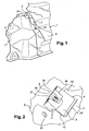
- a cockpit (1) of a motor vehicle is formed by a body body made of sheet metal (2).
- a first piece of shaped carpet (4) covers a first portion of the sheet (2).
- a second shaped polymer part (6) covers a second part of the sheet (2).
- the latter comprises holding means in the form of a tab (7) projecting from the upper main surface ( 8) of the polymer part (6).
- the tab (7) is formed by a plate (9) substantially parallel to the upper main surface (8) and overhanging the upper main surface (8) of the polymer part (6).
- a housing (10) is delimited by the wafer (9) and the upper main surface (8) covered by this wafer (9).
- the wafer (9) extends upwards with respect to the upper main surface (8) of the polymer part (6), being mounted on side legs (11). These legs (11) are oriented longitudinally. The height of the legs (11) determines the thickness of the housing (10) and thus the maximum thickness for a flanged area (12) of the piece of carpet (4).
- the rim area (12) of the piece of carpet (4) is slid (Arrow S in Figure 3 ) inside the housing (10), between a lower face (13) of the wafer (9) and the upper main surface (8) of the polymer part (6), covered by the wafer (9).
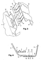
- the lower face (13) of the wafer (9) is provided with several excrescences.
- these excrescences are ribs (14).
- the ribs (14), four in number, extend from the underside (13) and are oriented towards the upper main surface (8) of the polymer piece (6). These ribs (14) do not touch the upper main surface (8), leaving a passage for the flanged area (12).
- These ribs (14) act as locking means of the piece of carpet (4) by its flange area (12).
- the ribs (14) are oriented in the longitudinal direction of the plate (9), corresponding to the insertion direction (Arrow S) of the flange (12) in the housing (10) under the paw (7).
- the ribs (14) are provided perpendicular to the underside (13) of the wafer (9).
- the ribs (14) are thus perpendicular to the upper main surface (8) of the polymer part (6).
- the ribs (14) are also perpendicular to the rim area (12) of the carpet piece (4).
- the ribs (14) extend over the entire length of the wafer (9). Two of the ribs (14) form the extension of two of the side jambs (11).
- the ribs (14) each have a rounded edge or slice (16) or with a curvature.
- the wafer (16) of each of the ribs (14) is thus curved back and forth, that is to say in the direction of insertion (Arrow S) of the flange (12) under the plate (7).
- the center of the radius of curvature is substantially placed at the level of the wafer (9).
- the plate (9) of the tab (7) comprises a front transverse flange (17). This is the edge located near the curved portion (16) of the ribs (14). To allow easy insertion of the rim (12) of the carpet piece (4) and / or to allow the piece of carpet (4) to follow the conformation of the sheet (12), the front transverse flange (17) is flared. This transverse flange (17) is thus bent upwards, that is to say opposite to the upper main surface (8) of the polymer part (6). In this way the inlet section of the housing (10) will be increased.
- a cutout (18) is formed in the plate (9) of the tab (7).
- the cut (18), substantially square shape, is at the rear of the plate (7), opposite the front transverse flange (17).
- This cutout (18) is delimited by two of the internal lateral jambs (11).
- the two internal lateral legs (11) continue in the longitudinal direction each by a rib (14).
- the cutting (18) of the wafer (9) corresponds a complementary zone or tongue (19) of the piece of carpet (4), extending in the plane beyond the flange (12).
- the cutout (18) is perpendicular to the tongue (19).
- the tongue (19) is placed between the two internal side jambs (11) of the tab (7).
- An opening (21) is formed in the tongue (19).
- Two convex portions in the form of lugs (22) protrude upwardly from the main surface (8) of the polymer piece (6).
- the cooperation of these lugs (22) with the opening (21) serves to prevent any return to the opposite of the insertion direction (S) and any output of the tab (19), the flange (12) and therefore the piece of carpet (4) out of the housing (10).
- fastening means (23) may be provided between the first piece of carpet (4) and the second piece of polymer (6).
Landscapes
- Engineering & Computer Science (AREA)
- Mechanical Engineering (AREA)
- Aviation & Aerospace Engineering (AREA)
- Transportation (AREA)
- Passenger Equipment (AREA)
- Body Structure For Vehicles (AREA)
- Paints Or Removers (AREA)
- Glass Compositions (AREA)
- Vehicle Interior And Exterior Ornaments, Soundproofing, And Insulation (AREA)
- Vehicle Step Arrangements And Article Storage (AREA)
Claims (11)
- Verkleidungsanordnung für eine Fahrgastzelle (1) eines Kraftfahrzeugs, die aufweist:- ein erstes Teil (4), das einen ersten Belag aus einem Material des Typs Teppich bildet, und- ein zweites Teil (6), das einen zweiten Belag aus einem Material des Typs Polymer bildet und das Mittel zum Halten des ersten Teils in Form einer Lasche (7) aufweist, die sich über einer Hauptoberfläche (8) des zweiten Teils (6) erstreckt, wobei ein Aufnahmesitz (10) zwischen der Lasche (7) und der Hauptoberfläche (8) des zweiten Teils (6) definiert ist, in dessen Innenraum sich eine Randzone (12) des ersten Teils (4) einsetzen lässt,dadurch gekennzeichnet, dass die Lasche (7) des zweiten Teils (6) mindestens eine Ausstülpung (14) aufweist, die sich in dem Aufnahmesitz (10) in Richtung der Hauptoberfläche (8) des zweiten Teils (6) ausbreitet, so dass die Randzone (12) des ersten Teils (4), während sie eingefügt wird, durch Einklemmen zwischen die Ausstülpung (14) und die Hauptoberfläche (8) des zweiten Teils (6) verriegelt wird.
- Anordnung nach Anspruch 1, dadurch gekennzeichnet, dass sich die Ausstülpung (14) im Wesentlichen senkrecht zur Hauptoberfläche (8) des zweiten Teils (6) ausbreitet.
- Anordnung nach Anspruch 1 oder 2, dadurch gekennzeichnet, dass die Ausstülpung eine Rippe (14) ist.
- Anordnung nach Anspruch 3, dadurch gekennzeichnet, dass sich die Rippe (14) im Wesentlichen auf der ganzen Länge der Lasche (7) längs der Einführungsrichtung der Randzone (12) des ersten Teils (4) ausbreitet.
- Anordnung nach Anspruch 3 oder 4, dadurch gekennzeichnet, dass die Rippe (14) einen gekrümmten Abschnitt (16) für den Eintritt des ersten Teils (4) aufweist.
- Anordnung nach einem der vorangehenden Ansprüche, dadurch gekennzeichnet, dass die Lasche (7) einen aufgeweiteten transversalen Rand (17) für den Eintritt des ersten Teils (4) aufweist.
- Anordnung nach einem der vorangehenden Ansprüche, dadurch gekennzeichnet, dass sich die Lasche (7), die sich über der Hauptoberfläche (8) des zweiten Teils (6) erstreckt, ausgehend von mindestens zwei seitlichen Stützen (11) ausbreitet.
- Anordnung nach Anspruch 7, dadurch gekennzeichnet, dass sich eine Zusatzzone (19) der Randzone (12) des ersten Teils (4) zwischen den zwei seitlichen Stützen (11) der Lasche (7) erstreckt.
- Anordnung nach Anspruch 7 oder 8, dadurch gekennzeichnet, dass zwei Rippen (14) die zwei seitlichen Stützen (11) der Lasche (7) verlängern.
- Anordnung nach Anspruch 8 oder 9, dadurch gekennzeichnet, dass die Lasche (7) einen Einschnitt (18) aufweist, der am Ort der Zusatzzone (19) der Randzone (12) des ersten Teils (4) liegt.
- Anordnung nach einem der vorangehenden Ansprüche, dadurch gekennzeichnet, dass das zweite Teil (6) mindestens einen konvexen Abschnitt (22) aufweist, der mit einer Öffnung (21) der Randzone (12) des ersten Teils (4) zusammenwirken kann.
Applications Claiming Priority (1)
| Application Number | Priority Date | Filing Date | Title |
|---|---|---|---|
| FR0651014A FR2898838B1 (fr) | 2006-03-23 | 2006-03-23 | Agencement d'habillage entre deux pieces pour un habitacle d'un vehicule automobile |
Publications (2)
| Publication Number | Publication Date |
|---|---|
| EP1839955A1 EP1839955A1 (de) | 2007-10-03 |
| EP1839955B1 true EP1839955B1 (de) | 2010-01-13 |
Family
ID=37451899
Family Applications (1)
| Application Number | Title | Priority Date | Filing Date |
|---|---|---|---|
| EP07300892A Not-in-force EP1839955B1 (de) | 2006-03-23 | 2007-03-22 | Verkleidungsanordnung zwischen zwei Teilen für ein Fahrerhaus eines Kraftfahrzeugs |
Country Status (5)
| Country | Link |
|---|---|
| EP (1) | EP1839955B1 (de) |
| AT (1) | ATE455013T1 (de) |
| DE (1) | DE602007004251D1 (de) |
| ES (1) | ES2339715T3 (de) |
| FR (1) | FR2898838B1 (de) |
Families Citing this family (1)
| Publication number | Priority date | Publication date | Assignee | Title |
|---|---|---|---|---|
| ES2461467B1 (es) * | 2012-11-16 | 2015-03-10 | Seat Sa | Unión de piezas laminares de perfil curvado |
Family Cites Families (5)
| Publication number | Priority date | Publication date | Assignee | Title |
|---|---|---|---|---|
| DE9016691U1 (de) * | 1990-12-10 | 1991-04-04 | APA GmbH & Co KG Otto Bauder, 7012 Fellbach | Befestigungselement für Fußmatten |
| US5724703A (en) * | 1996-12-31 | 1998-03-10 | Wu; Sheng-Ho | Positioning device for positioning a mat in a car |
| DE19845663A1 (de) * | 1998-10-05 | 2000-04-13 | Daimler Chrysler Ag | Befestigungselement insbesondere zur Befestigung einer Einlegematte an einem Bodenbelag |
| DE10259313B3 (de) * | 2002-12-18 | 2004-07-01 | Stankiewicz Gmbh | Formteil zur Halterung und Versteifung eines laschenförmigen Ausschnittteils in einem flächigen Gut |
| DE10330888B3 (de) * | 2003-07-09 | 2004-08-12 | Daimlerchrysler Ag | Klemmvorrichtung für ein Kraftfahrzeug |
-
2006
- 2006-03-23 FR FR0651014A patent/FR2898838B1/fr not_active Expired - Fee Related
-
2007
- 2007-03-22 ES ES07300892T patent/ES2339715T3/es active Active
- 2007-03-22 AT AT07300892T patent/ATE455013T1/de not_active IP Right Cessation
- 2007-03-22 DE DE602007004251T patent/DE602007004251D1/de active Active
- 2007-03-22 EP EP07300892A patent/EP1839955B1/de not_active Not-in-force
Also Published As
| Publication number | Publication date |
|---|---|
| ATE455013T1 (de) | 2010-01-15 |
| DE602007004251D1 (de) | 2010-03-04 |
| FR2898838B1 (fr) | 2008-12-19 |
| ES2339715T3 (es) | 2010-05-24 |
| EP1839955A1 (de) | 2007-10-03 |
| FR2898838A1 (fr) | 2007-09-28 |
Similar Documents
| Publication | Publication Date | Title |
|---|---|---|
| EP2651677B1 (de) | Baugruppe, insbesondere für ein kraftfahrzeug, mit einer äusseren haut und einer innenstruktur, die durch ein klebstoffkügelchen fixiert sind | |
| EP2900498B1 (de) | Strukturelles verkleidungsteil einer kraftfahrzeugseitentür und seitentür damit | |
| FR2968631A1 (fr) | Sous-ensemble, notamment de vehicule, a peau externe et structure interne fixees par cordon de colle | |
| FR2617696A1 (fr) | Armature de coussin pour siege de vehicule | |
| EP1839955B1 (de) | Verkleidungsanordnung zwischen zwei Teilen für ein Fahrerhaus eines Kraftfahrzeugs | |
| FR2989407A1 (fr) | Dispositif de commande d'ouverture interieure d'un ouvrant de vehicule. | |
| WO2011039458A1 (fr) | Habillage intérieur de véhicule automobile muni d'une poignée | |
| FR2917052A1 (fr) | Bandeau de hayon de vehicule automobile | |
| EP3792118B1 (de) | Verkleidungselement für lenksäule eines kraftfahrzeugs | |
| EP3575156B1 (de) | Deckel zum verschliessen einer wandöffnung | |
| EP2785563B1 (de) | Anordnung einer lateralen auskleidung für einen gepäckraum | |
| EP4034429B1 (de) | Abdeckvorrichtung für eine öffnungsplatte eines kraftfahrzeuges | |
| EP1288075B1 (de) | Starrer Belag für eine Trittstufe und Trittbrett mit diesem Belag | |
| EP1808322A1 (de) | Dichtelement für die Windschutzscheibe eines Kraftfahrzeugs | |
| EP2183149B1 (de) | Auskleidung für den heckspoiler eines motorfahrzeugs sowie motorfahrzeug mit mindestens einer solchen auskleidung | |
| WO2011095746A2 (fr) | Ensemble d'équipement de véhicule automobile et procédé de montage associé | |
| EP1720730B1 (de) | Mit ausschnitten für kabel versehener teppich für den fahrgastraum eines kraftfahrzeugs | |
| FR2982574A1 (fr) | Renfort d'habillage autour d'un boitier de commande sur un volant de vehicule | |
| FR2884201A1 (fr) | Ensemble de pare-chocs de vehicule automobile et vehicule automobile comprenant un tel ensemble. | |
| FR2929204A1 (fr) | Face avant de vehicule automobile avec un accessoire ornemental. | |
| EP4237288A1 (de) | Fahrzeug mit einer geräuschdämmenden auskleidung mit optimierter befestigung | |
| EP1736366B1 (de) | Anordnung zur Montage eines Innenausstattungspanels an einem Karosserieblech eines Automobils und zugehöriges Montageteil | |
| WO2011116949A1 (fr) | Agencement de coussin de securite gonflable comprenant un volet renforce | |
| FR2922495A3 (fr) | Planche de bord de vehicule adaptable en deux versions et procede de fabrication d'une serie de vehicules dotee d'une telle planche de bord | |
| FR3090557A1 (fr) | Elément d'habitacle pour véhicule automobile et ensemble comprenant un tel élément d'habitacle |
Legal Events
| Date | Code | Title | Description |
|---|---|---|---|
| PUAI | Public reference made under article 153(3) epc to a published international application that has entered the european phase |
Free format text: ORIGINAL CODE: 0009012 |
|
| AK | Designated contracting states |
Kind code of ref document: A1 Designated state(s): AT BE BG CH CY CZ DE DK EE ES FI FR GB GR HU IE IS IT LI LT LU LV MC MT NL PL PT RO SE SI SK TR |
|
| AX | Request for extension of the european patent |
Extension state: AL BA HR MK YU |
|
| 17P | Request for examination filed |
Effective date: 20080321 |
|
| 17Q | First examination report despatched |
Effective date: 20080429 |
|
| AKX | Designation fees paid |
Designated state(s): AT BE BG CH CY CZ DE DK EE ES FI FR GB GR HU IE IS IT LI LT LU LV MC MT NL PL PT RO SE SI SK TR |
|
| GRAP | Despatch of communication of intention to grant a patent |
Free format text: ORIGINAL CODE: EPIDOSNIGR1 |
|
| GRAS | Grant fee paid |
Free format text: ORIGINAL CODE: EPIDOSNIGR3 |
|
| GRAA | (expected) grant |
Free format text: ORIGINAL CODE: 0009210 |
|
| AK | Designated contracting states |
Kind code of ref document: B1 Designated state(s): AT BE BG CH CY CZ DE DK EE ES FI FR GB GR HU IE IS IT LI LT LU LV MC MT NL PL PT RO SE SI SK TR |
|
| REG | Reference to a national code |
Ref country code: GB Ref legal event code: FG4D Free format text: NOT ENGLISH |
|
| REG | Reference to a national code |
Ref country code: CH Ref legal event code: EP |
|
| REG | Reference to a national code |
Ref country code: IE Ref legal event code: FG4D |
|
| REF | Corresponds to: |
Ref document number: 602007004251 Country of ref document: DE Date of ref document: 20100304 Kind code of ref document: P |
|
| REG | Reference to a national code |
Ref country code: NL Ref legal event code: VDEP Effective date: 20100113 |
|
| REG | Reference to a national code |
Ref country code: ES Ref legal event code: FG2A Ref document number: 2339715 Country of ref document: ES Kind code of ref document: T3 |
|
| LTIE | Lt: invalidation of european patent or patent extension |
Effective date: 20100113 |
|
| PG25 | Lapsed in a contracting state [announced via postgrant information from national office to epo] |
Ref country code: AT Free format text: LAPSE BECAUSE OF FAILURE TO SUBMIT A TRANSLATION OF THE DESCRIPTION OR TO PAY THE FEE WITHIN THE PRESCRIBED TIME-LIMIT Effective date: 20100113 |
|
| PG25 | Lapsed in a contracting state [announced via postgrant information from national office to epo] |
Ref country code: PT Free format text: LAPSE BECAUSE OF FAILURE TO SUBMIT A TRANSLATION OF THE DESCRIPTION OR TO PAY THE FEE WITHIN THE PRESCRIBED TIME-LIMIT Effective date: 20100513 Ref country code: NL Free format text: LAPSE BECAUSE OF FAILURE TO SUBMIT A TRANSLATION OF THE DESCRIPTION OR TO PAY THE FEE WITHIN THE PRESCRIBED TIME-LIMIT Effective date: 20100113 Ref country code: LT Free format text: LAPSE BECAUSE OF FAILURE TO SUBMIT A TRANSLATION OF THE DESCRIPTION OR TO PAY THE FEE WITHIN THE PRESCRIBED TIME-LIMIT Effective date: 20100113 Ref country code: IS Free format text: LAPSE BECAUSE OF FAILURE TO SUBMIT A TRANSLATION OF THE DESCRIPTION OR TO PAY THE FEE WITHIN THE PRESCRIBED TIME-LIMIT Effective date: 20100513 |
|
| REG | Reference to a national code |
Ref country code: IE Ref legal event code: FD4D |
|
| PG25 | Lapsed in a contracting state [announced via postgrant information from national office to epo] |
Ref country code: SI Free format text: LAPSE BECAUSE OF FAILURE TO SUBMIT A TRANSLATION OF THE DESCRIPTION OR TO PAY THE FEE WITHIN THE PRESCRIBED TIME-LIMIT Effective date: 20100113 Ref country code: PL Free format text: LAPSE BECAUSE OF FAILURE TO SUBMIT A TRANSLATION OF THE DESCRIPTION OR TO PAY THE FEE WITHIN THE PRESCRIBED TIME-LIMIT Effective date: 20100113 Ref country code: LV Free format text: LAPSE BECAUSE OF FAILURE TO SUBMIT A TRANSLATION OF THE DESCRIPTION OR TO PAY THE FEE WITHIN THE PRESCRIBED TIME-LIMIT Effective date: 20100113 Ref country code: FI Free format text: LAPSE BECAUSE OF FAILURE TO SUBMIT A TRANSLATION OF THE DESCRIPTION OR TO PAY THE FEE WITHIN THE PRESCRIBED TIME-LIMIT Effective date: 20100113 |
|
| BERE | Be: lapsed |
Owner name: RENAULT S.A.S. Effective date: 20100331 |
|
| PG25 | Lapsed in a contracting state [announced via postgrant information from national office to epo] |
Ref country code: RO Free format text: LAPSE BECAUSE OF FAILURE TO SUBMIT A TRANSLATION OF THE DESCRIPTION OR TO PAY THE FEE WITHIN THE PRESCRIBED TIME-LIMIT Effective date: 20100113 Ref country code: MC Free format text: LAPSE BECAUSE OF NON-PAYMENT OF DUE FEES Effective date: 20100331 Ref country code: CY Free format text: LAPSE BECAUSE OF FAILURE TO SUBMIT A TRANSLATION OF THE DESCRIPTION OR TO PAY THE FEE WITHIN THE PRESCRIBED TIME-LIMIT Effective date: 20100113 Ref country code: EE Free format text: LAPSE BECAUSE OF FAILURE TO SUBMIT A TRANSLATION OF THE DESCRIPTION OR TO PAY THE FEE WITHIN THE PRESCRIBED TIME-LIMIT Effective date: 20100113 Ref country code: GR Free format text: LAPSE BECAUSE OF FAILURE TO SUBMIT A TRANSLATION OF THE DESCRIPTION OR TO PAY THE FEE WITHIN THE PRESCRIBED TIME-LIMIT Effective date: 20100414 Ref country code: IE Free format text: LAPSE BECAUSE OF FAILURE TO SUBMIT A TRANSLATION OF THE DESCRIPTION OR TO PAY THE FEE WITHIN THE PRESCRIBED TIME-LIMIT Effective date: 20100113 Ref country code: SE Free format text: LAPSE BECAUSE OF FAILURE TO SUBMIT A TRANSLATION OF THE DESCRIPTION OR TO PAY THE FEE WITHIN THE PRESCRIBED TIME-LIMIT Effective date: 20100113 |
|
| PLBE | No opposition filed within time limit |
Free format text: ORIGINAL CODE: 0009261 |
|
| STAA | Information on the status of an ep patent application or granted ep patent |
Free format text: STATUS: NO OPPOSITION FILED WITHIN TIME LIMIT |
|
| PG25 | Lapsed in a contracting state [announced via postgrant information from national office to epo] |
Ref country code: CZ Free format text: LAPSE BECAUSE OF FAILURE TO SUBMIT A TRANSLATION OF THE DESCRIPTION OR TO PAY THE FEE WITHIN THE PRESCRIBED TIME-LIMIT Effective date: 20100113 Ref country code: BG Free format text: LAPSE BECAUSE OF FAILURE TO SUBMIT A TRANSLATION OF THE DESCRIPTION OR TO PAY THE FEE WITHIN THE PRESCRIBED TIME-LIMIT Effective date: 20100413 Ref country code: SK Free format text: LAPSE BECAUSE OF FAILURE TO SUBMIT A TRANSLATION OF THE DESCRIPTION OR TO PAY THE FEE WITHIN THE PRESCRIBED TIME-LIMIT Effective date: 20100113 |
|
| 26N | No opposition filed |
Effective date: 20101014 |
|
| PG25 | Lapsed in a contracting state [announced via postgrant information from national office to epo] |
Ref country code: DK Free format text: LAPSE BECAUSE OF FAILURE TO SUBMIT A TRANSLATION OF THE DESCRIPTION OR TO PAY THE FEE WITHIN THE PRESCRIBED TIME-LIMIT Effective date: 20100113 |
|
| PG25 | Lapsed in a contracting state [announced via postgrant information from national office to epo] |
Ref country code: BE Free format text: LAPSE BECAUSE OF NON-PAYMENT OF DUE FEES Effective date: 20100331 |
|
| PG25 | Lapsed in a contracting state [announced via postgrant information from national office to epo] |
Ref country code: MT Free format text: LAPSE BECAUSE OF FAILURE TO SUBMIT A TRANSLATION OF THE DESCRIPTION OR TO PAY THE FEE WITHIN THE PRESCRIBED TIME-LIMIT Effective date: 20100113 |
|
| PGRI | Patent reinstated in contracting state [announced from national office to epo] |
Ref country code: IT Effective date: 20110501 |
|
| REG | Reference to a national code |
Ref country code: CH Ref legal event code: PL |
|
| PG25 | Lapsed in a contracting state [announced via postgrant information from national office to epo] |
Ref country code: CH Free format text: LAPSE BECAUSE OF NON-PAYMENT OF DUE FEES Effective date: 20110331 Ref country code: LI Free format text: LAPSE BECAUSE OF NON-PAYMENT OF DUE FEES Effective date: 20110331 |
|
| PG25 | Lapsed in a contracting state [announced via postgrant information from national office to epo] |
Ref country code: HU Free format text: LAPSE BECAUSE OF FAILURE TO SUBMIT A TRANSLATION OF THE DESCRIPTION OR TO PAY THE FEE WITHIN THE PRESCRIBED TIME-LIMIT Effective date: 20100714 Ref country code: LU Free format text: LAPSE BECAUSE OF NON-PAYMENT OF DUE FEES Effective date: 20100322 |
|
| PG25 | Lapsed in a contracting state [announced via postgrant information from national office to epo] |
Ref country code: TR Free format text: LAPSE BECAUSE OF FAILURE TO SUBMIT A TRANSLATION OF THE DESCRIPTION OR TO PAY THE FEE WITHIN THE PRESCRIBED TIME-LIMIT Effective date: 20100113 |
|
| REG | Reference to a national code |
Ref country code: FR Ref legal event code: PLFP Year of fee payment: 9 |
|
| REG | Reference to a national code |
Ref country code: FR Ref legal event code: PLFP Year of fee payment: 10 |
|
| REG | Reference to a national code |
Ref country code: FR Ref legal event code: PLFP Year of fee payment: 11 |
|
| PGFP | Annual fee paid to national office [announced via postgrant information from national office to epo] |
Ref country code: FR Payment date: 20170322 Year of fee payment: 11 Ref country code: DE Payment date: 20170322 Year of fee payment: 11 |
|
| PGFP | Annual fee paid to national office [announced via postgrant information from national office to epo] |
Ref country code: GB Payment date: 20170322 Year of fee payment: 11 |
|
| PGFP | Annual fee paid to national office [announced via postgrant information from national office to epo] |
Ref country code: ES Payment date: 20170315 Year of fee payment: 11 |
|
| PGFP | Annual fee paid to national office [announced via postgrant information from national office to epo] |
Ref country code: IT Payment date: 20170323 Year of fee payment: 11 |
|
| REG | Reference to a national code |
Ref country code: DE Ref legal event code: R119 Ref document number: 602007004251 Country of ref document: DE |
|
| GBPC | Gb: european patent ceased through non-payment of renewal fee |
Effective date: 20180322 |
|
| PG25 | Lapsed in a contracting state [announced via postgrant information from national office to epo] |
Ref country code: DE Free format text: LAPSE BECAUSE OF NON-PAYMENT OF DUE FEES Effective date: 20181002 |
|
| PG25 | Lapsed in a contracting state [announced via postgrant information from national office to epo] |
Ref country code: GB Free format text: LAPSE BECAUSE OF NON-PAYMENT OF DUE FEES Effective date: 20180322 Ref country code: IT Free format text: LAPSE BECAUSE OF NON-PAYMENT OF DUE FEES Effective date: 20180322 |
|
| PG25 | Lapsed in a contracting state [announced via postgrant information from national office to epo] |
Ref country code: FR Free format text: LAPSE BECAUSE OF NON-PAYMENT OF DUE FEES Effective date: 20180331 |
|
| REG | Reference to a national code |
Ref country code: ES Ref legal event code: FD2A Effective date: 20190911 |
|
| PG25 | Lapsed in a contracting state [announced via postgrant information from national office to epo] |
Ref country code: ES Free format text: LAPSE BECAUSE OF NON-PAYMENT OF DUE FEES Effective date: 20180323 |