EP1839963A2 - Airbag für ein Kraftfahrzeug - Google Patents
Airbag für ein Kraftfahrzeug Download PDFInfo
- Publication number
- EP1839963A2 EP1839963A2 EP07104719A EP07104719A EP1839963A2 EP 1839963 A2 EP1839963 A2 EP 1839963A2 EP 07104719 A EP07104719 A EP 07104719A EP 07104719 A EP07104719 A EP 07104719A EP 1839963 A2 EP1839963 A2 EP 1839963A2
- Authority
- EP
- European Patent Office
- Prior art keywords
- central portion
- loading portion
- pelvis
- airbag assembly
- inflator
- Prior art date
- Legal status (The legal status is an assumption and is not a legal conclusion. Google has not performed a legal analysis and makes no representation as to the accuracy of the status listed.)
- Withdrawn
Links
Images

Classifications
-
- B—PERFORMING OPERATIONS; TRANSPORTING
- B60—VEHICLES IN GENERAL
- B60R—VEHICLES, VEHICLE FITTINGS, OR VEHICLE PARTS, NOT OTHERWISE PROVIDED FOR
- B60R21/00—Arrangements or fittings on vehicles for protecting or preventing injuries to occupants or pedestrians in case of accidents or other traffic risks
- B60R21/02—Occupant safety arrangements or fittings, e.g. crash pads
- B60R21/16—Inflatable occupant restraints or confinements designed to inflate upon impact or impending impact, e.g. air bags
- B60R21/20—Arrangements for storing inflatable members in their non-use or deflated condition; Arrangement or mounting of air bag modules or components
- B60R21/207—Arrangements for storing inflatable members in their non-use or deflated condition; Arrangement or mounting of air bag modules or components in vehicle seats
-
- B—PERFORMING OPERATIONS; TRANSPORTING
- B60—VEHICLES IN GENERAL
- B60R—VEHICLES, VEHICLE FITTINGS, OR VEHICLE PARTS, NOT OTHERWISE PROVIDED FOR
- B60R21/00—Arrangements or fittings on vehicles for protecting or preventing injuries to occupants or pedestrians in case of accidents or other traffic risks
- B60R21/02—Occupant safety arrangements or fittings, e.g. crash pads
- B60R21/16—Inflatable occupant restraints or confinements designed to inflate upon impact or impending impact, e.g. air bags
- B60R21/23—Inflatable members
- B60R21/231—Inflatable members characterised by their shape, construction or spatial configuration
-
- B—PERFORMING OPERATIONS; TRANSPORTING
- B60—VEHICLES IN GENERAL
- B60R—VEHICLES, VEHICLE FITTINGS, OR VEHICLE PARTS, NOT OTHERWISE PROVIDED FOR
- B60R21/00—Arrangements or fittings on vehicles for protecting or preventing injuries to occupants or pedestrians in case of accidents or other traffic risks
- B60R21/02—Occupant safety arrangements or fittings, e.g. crash pads
- B60R21/16—Inflatable occupant restraints or confinements designed to inflate upon impact or impending impact, e.g. air bags
- B60R21/23—Inflatable members
- B60R21/231—Inflatable members characterised by their shape, construction or spatial configuration
- B60R21/2334—Expansion control features
- B60R21/2346—Soft diffusers
-
- B—PERFORMING OPERATIONS; TRANSPORTING
- B60—VEHICLES IN GENERAL
- B60R—VEHICLES, VEHICLE FITTINGS, OR VEHICLE PARTS, NOT OTHERWISE PROVIDED FOR
- B60R21/00—Arrangements or fittings on vehicles for protecting or preventing injuries to occupants or pedestrians in case of accidents or other traffic risks
- B60R21/02—Occupant safety arrangements or fittings, e.g. crash pads
- B60R21/16—Inflatable occupant restraints or confinements designed to inflate upon impact or impending impact, e.g. air bags
- B60R21/23—Inflatable members
- B60R21/231—Inflatable members characterised by their shape, construction or spatial configuration
- B60R21/23138—Inflatable members characterised by their shape, construction or spatial configuration specially adapted for side protection
- B60R2021/23146—Inflatable members characterised by their shape, construction or spatial configuration specially adapted for side protection seat mounted
Definitions
- the present invention relates to motor vehicles and in particular to a side impact airbag assembly for a motor vehicle.
- Vehicle airbags are used to protect vehicle occupants in the event of a collision. Airbags were initially provided on the dashboard and steering wheel of vehicles to protect against front end collisions. More recently, side impact airbags have been developed to protect vehicle occupants in the event of a side impact. Side impact airbags are inflated by an inflator that inflates the airbag with a gaseous medium when an impact is detected by side impact sensors provided on the vehicle.
- Some prior art side impact airbags when inflated extend from a mounting location on one side of a seat back forwardly between the vehicle door and the occupant to cover the entire side of an occupant's body.
- This type of side impact airbag when deployed, extends across the rib cage of an occupant's body.
- Such airbags may cause additional unwanted rib deflection as they press against rib cage that is generally less robust than a person's hip or shoulder.
- Tests for side impact airbags include the current IIHS high hooded barrier side impact test and a new more severe FMVSS 214 Oblique Pole Test. There is a need to develop side impact airbags that meet all of the requirements of such tests.
- the distance between an H point and knee pivot for the 5 th percentile female anthropomorphic dummy is less than the distance between the H point and knee pivot of a 50 th percentile male anthropomorphic dummy, requiring the female dummy to sit more forward in the seat.
- the 5 th percentile female anthropomorphic dummy has a pelvis H point that is shifted forward to an extent that is forward of the pelvis H point for the 50 th percentile male anthropomorphic dummy. This creates a problem for side airbags designed to cover at least a 50 th percentile male occupant because this does not assure forward coverage for 5 th percentile females.
- an airbag assembly for a vehicle occupant protection system characterised in that the airbag assembly comprises an inflatable fabric enclosure having a pelvis loading portion, a shoulder loading portion, a central portion, the inflator being positioned to distribute gas flow such that the gas is supplied to the enclosure in a controlled manner to provide pressure at a first level in the pelvis loading portion and at a second level in the shoulder loading portion that is less than the first level.
- the airbag may be in a B-shape having a vertical axis and may be formed by an upper lobe that is configured to target the shoulder for loading, a lower lobe that is configured to target the pelvis for loading, and a constricted central portion that is configured to avoid loading the thorax of a seat occupant.
- the central portion may be a constricted central portion.
- the airbag assembly may further comprise a first vent hole provided in the pelvis loading portion and a second vent hole provided in the shoulder loading portion.
- the inflator may be positioned to distribute gas flow such that the majority of the gas is dispensed through a port directly into the pelvis loading portion with the balance of the gas being dispensed into the central portion, the gas being provided to the shoulder loading portion through the central portion.
- the inflator may have a port through which a volume of a gas is dispensed and one or more restrictions in the central portion to maintain the difference between the first and second levels during a deployment phase of the airbag assembly.
- the pelvis loading portion may be disposed below the central portion and the shoulder loading portion may be disposed above the central portion, the pelvis loading portion and the shoulder loading portion may be both laterally wider than the central portion such that the inflated fabric enclosure is hour-glass shaped.
- the pelvis loading portion of the airbag assembly may extend downwardly and forwardly from the central portion, the shoulder loading portion may extend upwardly and forwardly from the central portion and the central portion may be limited in the forward direction of extension to a location corresponding to the position of a back of an occupant.
- the central portion may have a reduced cross-sectional area when fully inflated than both the cross-sectional area of the pelvis loading portion and the shoulder loading portion when fully inflated, the degree of reduction of the cross-sectional area of the central portion may be controlled by providing a baffle that extends at least partially across the central portion.
- the baffle may be a sewn partial baffle that extends partially across the central portion.
- the enclosure may further comprise an inner wall, an outer wall and inner and outer wall reinforcement layers disposed in at least the central portion.
- the inner reinforcement layer may be secured to the inside wall and the outer reinforcement layer may be secured to the outside wall.
- the inner wall and the outer wall may each extend over the pelvis loading portion, the central portion and the shoulder loading portion.
- the shoulder loading portion may extend vertically and horizontally a sufficient distance to cover and protect a shoulder of an occupant and the pelvis loading portion may extend vertically and horizontally sufficiently to cover and protect a pelvis of the occupant, wherein the term sufficient distance is defined as coverage for the occupant provided that the occupant is between 5 th percentile female and 50 th percentile male of the population in height.
- the inflator may be secured to a vehicle seat back and to the central portion of the airbag assembly.
- the inflator may be positioned within the fabric enclosure and may be attached to a vehicle seat back, the inflator may have a port oriented to direct gas downwardly into the pelvis loading portion with a lesser portion of the gas flow being directed into the central portion.
- a airbag system for protecting an occupant of a vehicle, the system comprising a sensor to sense whether the vehicle is involved in a collision and generate a collision detection signal, a controller to receive the collision detection signal from the sensor and generate an activation signal and an airbag assembly constructed in accordance with said first aspect of the invention wherein the inflator of the airbag assembly is operable to generate gas in response to receiving the activation signal from the controller.
- a motor vehicle having at least one airbag system constructed in accordance with said second aspect of the invention.
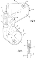
- a vehicle seat 10 is shown with an inflatable fabric enclosure in the form of an airbag 12 shown in its inflated position and an inflator 16.
- the airbag 12 is shown as it is inflated on one side of the vehicle seat 10. Referring specifically to Figure 2, the airbag 12 is inflated and assumes an hour-glass shape in the space between the door 18 of a vehicle 20 and the vehicle seat 10.
- the airbag 12 is shown in greater detail.
- the airbag 12 has a shoulder loading portion 22 that is inflated adjacent to the shoulder of a seat occupant.
- the shoulder loading portion 22 is intended to be large enough to be positioned adjacent to the shoulder of a person who is between 5 th percentile female and 50 th percentile male of the height of the average person.
- a central portion 24 is provided in the center of the airbag 12 and a pelvis loading portion 26 is provided below the central portion 24.
- the pelvis loading portion 26 when inflated is disposed adjacent the hip of a occupant of the seat who is between the 5 th percentile female and the 50 th percentile male of the height of the average person.
- the pelvis loading portion 26 extends forwardly to an extent that a person's hip that is a 5% female anthropomorphic dummy height standard is covered and protected.
- the airbag 12 has a B-shaped configuration. While the shape is not strictly a B-shape the shape of the bag may be described as having a vertical axis V which depending upon the orientation of the seat may be somewhat inclined rearwardly.
- the shoulder loading portion 22 is disposed above the central portion.
- the pelvis loading portion 26 is disposed below the central portion.
- a shoulder portion vent 28 is provided in the shoulder loading portion 22.
- a hip portion vent 30 is provided in the pelvis loading portion 26. The vents 28, 30 are provided to permit air to escape from the airbag 12.
- the construction of the airbag 12 is shown to include an inside wall 34 and an outside wall 36 that are joined together to form the basic construction of the airbag 12.
- the fabric from which the walls and other parts of the airbag are formed may have a silicone coating for increasing the extent of air pressure retention of the air bag.
- An inner reinforcement layer 38 is sewn to the inside wall 34.
- An outer reinforcement layer 40 is sewn to the outside wall 36.
- the inner and outer reinforcement layers 38, 40 are connected to the inside wall 34 and outside wall 36 by reinforcement layer attachment seams 42. Additional reinforcement layers may be provided to strengthen certain areas.
- An expansion control baffle 46 may be provided in the central portion 24 to control the rate of inflation of the different portions of the airbag.
- the length of the expansion control baffle 46 may be changed to control the pressure in the shoulder loading portion 22 and the pelvis loading portion 26.
- the length of the baffle 46 may extend to the full width of the central portion 24. Gas is permitted to flow past the baffle 46 through a gap 48, or window. Pressure distribution may be tuned by controlling the size of the gap 48, or window. Pressure may also be controlled or tuned by changing the location of the gap 48, or window, relative to the inflator 16.
- Additional baffles may be provided to control pressure and facilitate shaping the airbag when deployed.
- the baffle or baffles may be formed by sewing the fabric of the central portion 24.
- a peripheral seam 50 is provided around the periphery of the airbag 12 that joins the inside wall 34 and outside wall 36 together about the periphery.
- the inflator 16 is disposed within an inflator housing 51 that has a port 52 that is directed downwardly into the pelvis loading portion 26 of the airbag 12. The majority of the gas expelled from the inflator 16 is directed toward the pelvis loading portion 26.
- the inflator 16 is assembled within the inflator housing 51 that also has a side port 54. Side port 54 ports gas from the inflator 16 into the central portion 24 of the airbag 12. Gas flowing from the inflator 16 into the shoulder loading portion 22 is initially directed into the central portion 24 and pelvis loading portion 26 and then flows into the shoulder loading portion 22. This has the effect of initially reducing the volume of gas flowing into the shoulder loading portion 22.
- Access holes 56 are provided in the inflator housing 51 to facilitate securing the inflator 16 to a vehicle seat 10.
- the pressure within the pelvis loading portion 26 is preferably between 135 to 210 kPa (20 to 30 psi) when loaded by an occupant.
- the pressure in the shoulder loading portion 22 is slightly lower and may be between 102 to 175 kPa (15 to 25 psi) when loaded by an occupant.
- the differential pressure between the shoulder loading portion 22 and pelvis loading portion 26 may be tuned by several different approaches.
- One way is to modify the mounting height of the inflator 16 relative to the airbag 12. By placing the inflator 16 lower in the airbag 12 the pelvis loading portion 26 will tend initially to fill with a greater volume and result in a higher pressure during inflation.
- Another way to control the level of pressure between the shoulder loading portion 22 and the pelvis loading portion 26 is to control the internal air flow through the central portion 24.
- the central portion 24 may be configured to provide a reduced cross-section when inflated.
- an expansion control baffle 46 may provided of varying length or additional expansion control baffles may be provided within the central portion 24.
- the location of the baffle 46 relative to the side port 54 may be determined based upon the desired relative pressures.
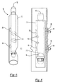
- the inflator 16 and inflator housing 51 are shown in greater detail.
- the inflator housing 51 includes a port 52 that is oriented downwardly.
- Side port 54 is oriented to expel gas into the central portion 24.
- Access holes 56 are provided in the side walls of the inflator housing 51 to receive fasteners, such as bolts or studs 62 and nuts 68, that secure the inflator 16, inflator housing 51 and airbag 12 to a vehicle seat back frame (not shown).
- the fasteners 62 extend through holes provided in the central portion 24 of the airbag 12.
- the reinforcement layers 38, 40 that define the central portion 24 provide added burst strength adjacent to the inflator 16. Pressure distribution may be controlled in part by changing the position of the inflator 16 within the inflator housing 51.
- pressure distribution may be controlled by changing the position of the airbag 12 relative to the inflator housing 51 by relocating the holes in the airbag 12.
Landscapes
- Engineering & Computer Science (AREA)
- Mechanical Engineering (AREA)
- Air Bags (AREA)
Applications Claiming Priority (1)
| Application Number | Priority Date | Filing Date | Title |
|---|---|---|---|
| US11/278,292 US7448645B2 (en) | 2006-03-31 | 2006-03-31 | Contoured side impact airbag |
Publications (2)
| Publication Number | Publication Date |
|---|---|
| EP1839963A2 true EP1839963A2 (de) | 2007-10-03 |
| EP1839963A3 EP1839963A3 (de) | 2009-07-01 |
Family
ID=38236415
Family Applications (1)
| Application Number | Title | Priority Date | Filing Date |
|---|---|---|---|
| EP07104719A Withdrawn EP1839963A3 (de) | 2006-03-31 | 2007-03-22 | Airbag für ein Kraftfahrzeug |
Country Status (2)
| Country | Link |
|---|---|
| US (1) | US7448645B2 (de) |
| EP (1) | EP1839963A3 (de) |
Cited By (1)
| Publication number | Priority date | Publication date | Assignee | Title |
|---|---|---|---|---|
| US7695064B2 (en) | 2008-06-24 | 2010-04-13 | Gm Global Technology Operations, Inc. | Vehicle seat side air bag |
Families Citing this family (32)
| Publication number | Priority date | Publication date | Assignee | Title |
|---|---|---|---|---|
| US7396040B2 (en) * | 2005-03-22 | 2008-07-08 | Autoliv Asp, Inc. | Airbag cushion with integrated inflator |
| WO2006132990A1 (en) * | 2005-06-03 | 2006-12-14 | Abc Group, Inc. | Active bolster |
| US7980589B2 (en) | 2005-11-17 | 2011-07-19 | Salflex Polymers Ltd. | Inflatable bolster |
| WO2007056849A1 (en) * | 2005-11-17 | 2007-05-24 | Salflex Polymers Ltd. | Bolster deployment pattern |
| JP5120599B2 (ja) * | 2006-06-20 | 2013-01-16 | マツダ株式会社 | サイドエアバッグ装置 |
| JP4245031B2 (ja) * | 2006-09-28 | 2009-03-25 | トヨタ自動車株式会社 | 車両用サイドエアバッグ装置 |
| JP2008189132A (ja) * | 2007-02-05 | 2008-08-21 | Toyoda Gosei Co Ltd | サイドエアバッグ装置 |
| US7766379B2 (en) * | 2007-09-24 | 2010-08-03 | Nissan Technical Center North America, Inc. | Side airbag apparatus and method |
| DE102008037811B4 (de) * | 2007-11-02 | 2020-04-16 | Daimler Ag | Rückhaltesystem mit verschließbaren Luftdurchströmöffnungen |
| JP5125596B2 (ja) * | 2008-02-22 | 2013-01-23 | 豊田合成株式会社 | 側突用エアバッグ装置 |
| JP5201090B2 (ja) * | 2008-09-30 | 2013-06-05 | 豊田合成株式会社 | エアバッグ |
| DE102009016606B4 (de) * | 2009-04-08 | 2014-08-28 | Autoliv Development Ab | Höhenverstellbarer Kraftfahrzeugsitz mit einem Seitengassack und Kraftfahrzeug mit einem solchen Fahrzeugsitz |
| DE102009016800B4 (de) * | 2009-04-09 | 2017-10-05 | Volkswagen Ag | Seitenairbagmodul für ein Kraftfahrzeug |
| JP5045708B2 (ja) * | 2009-06-05 | 2012-10-10 | 豊田合成株式会社 | サイドエアバッグ装置 |
| US8459689B2 (en) | 2009-12-24 | 2013-06-11 | Salflex Polymers Ltd. | Passenger side active knee bolster |
| EP2481642B1 (de) * | 2010-01-12 | 2014-11-12 | Mitsubishi Jidosha Kogyo Kabushiki Kaisha | Seitenairbag |
| US8376396B2 (en) * | 2010-01-15 | 2013-02-19 | Honda Motor Co., Ltd. | Multi-chamber knee airbag |
| WO2011137517A1 (en) | 2010-05-05 | 2011-11-10 | Salflex Polymers Ltd. | Injection molded inflatable active bolster |
| US8579325B2 (en) | 2010-11-09 | 2013-11-12 | Salflex Polymers Ltd. | Active bolster |
| CN102834303B (zh) * | 2010-11-17 | 2015-07-01 | 丰田自动车株式会社 | 车辆用侧面安全气囊装置 |
| US9254808B2 (en) | 2011-02-07 | 2016-02-09 | Salflex Polymers Limited | Active bolster assembly |
| JP6001863B2 (ja) * | 2011-12-20 | 2016-10-05 | オートリブ ディベロップメント エービー | サイドエアバッグ付きシート |
| JP5787097B2 (ja) * | 2012-07-06 | 2015-09-30 | 豊田合成株式会社 | エアバッグ装置 |
| US9616839B2 (en) * | 2014-05-18 | 2017-04-11 | Toyota Motor Engineering & Manufacturing North America, Inc. | H-point referenced seat cushion airbag system |
| KR101637205B1 (ko) * | 2015-09-30 | 2016-07-20 | 아우토리브 디벨롭먼트 아베 | 자동차용 측면 에어백 |
| US9573551B1 (en) * | 2015-11-06 | 2017-02-21 | Autoliv Asp, Inc. | Side airbag cushion and method of manufacture |
| US9827940B2 (en) * | 2016-03-16 | 2017-11-28 | Autoliv Asp, Inc. | Side airbag with internal diffuser |
| US10369956B2 (en) | 2017-03-20 | 2019-08-06 | Ford Global Technologies, Llc | Side airbag with necking chamber |
| US10988100B2 (en) | 2019-08-29 | 2021-04-27 | Ford Global Technologies, Llc | Side airbag including non-expandable region |
| US11383670B2 (en) * | 2019-09-30 | 2022-07-12 | Toyoda Gosei Co., Ltd. | Side airbag apparatus |
| KR102729838B1 (ko) * | 2020-02-16 | 2024-11-14 | 아우토리브 디벨롭먼트 아베 | 에어백 장치 및 차량용 시트 |
| JPWO2021166530A1 (de) * | 2020-02-21 | 2021-08-26 |
Family Cites Families (14)
| Publication number | Priority date | Publication date | Assignee | Title |
|---|---|---|---|---|
| US5556128A (en) * | 1994-11-24 | 1996-09-17 | Volkswagen Ag | Safety arrangement for a vehicle occupant |
| DE29517372U1 (de) * | 1995-11-02 | 1996-02-01 | Trw Repa Gmbh | Gassack-Seitenaufprall-Schutzeinrichtung |
| GB2324280A (en) * | 1997-04-18 | 1998-10-21 | Alliedsignal Deutschland Gmbh | A side impact airbag and a method of folding an airbag |
| JP3726518B2 (ja) * | 1998-11-18 | 2005-12-14 | タカタ株式会社 | エアバッグ |
| DE29822159U1 (de) * | 1998-12-11 | 1999-05-12 | Trw Repa Gmbh | Gassack-Seitenaufprall-Schutzeinrichtung |
| EP1122134B1 (de) | 2000-02-01 | 2005-02-16 | Delphi Automotive Systems Sungwoo Co., Ltd. | Seitenairbagsystem und dessen Herstellungsverfahren |
| US20040124615A1 (en) | 2001-06-08 | 2004-07-01 | Toshinori Tanase | Side air bag device |
| JP3915544B2 (ja) * | 2002-02-25 | 2007-05-16 | タカタ株式会社 | エアバッグ装置 |
| US20030168836A1 (en) | 2002-03-11 | 2003-09-11 | Eiji Sato | Side airbag apparatus |
| US7168733B2 (en) | 2002-12-27 | 2007-01-30 | Takata Corporation | Airbag apparatus |
| JP4285167B2 (ja) | 2003-01-30 | 2009-06-24 | タカタ株式会社 | 側突用エアバッグ装置 |
| GB2402111A (en) * | 2003-05-27 | 2004-12-01 | Autoliv Dev | Air bag with two chambers sealed by a strap |
| US7063350B2 (en) | 2003-09-23 | 2006-06-20 | Autoliv Asp, Inc. | Dual chamber side airbag apparatus and method |
| GB2406312A (en) * | 2003-09-25 | 2005-03-30 | Autoliv Dev | Gas deflector |
-
2006
- 2006-03-31 US US11/278,292 patent/US7448645B2/en active Active
-
2007
- 2007-03-22 EP EP07104719A patent/EP1839963A3/de not_active Withdrawn
Cited By (1)
| Publication number | Priority date | Publication date | Assignee | Title |
|---|---|---|---|---|
| US7695064B2 (en) | 2008-06-24 | 2010-04-13 | Gm Global Technology Operations, Inc. | Vehicle seat side air bag |
Also Published As
| Publication number | Publication date |
|---|---|
| US7448645B2 (en) | 2008-11-11 |
| EP1839963A3 (de) | 2009-07-01 |
| US20070228699A1 (en) | 2007-10-04 |
Similar Documents
| Publication | Publication Date | Title |
|---|---|---|
| EP1839963A2 (de) | Airbag für ein Kraftfahrzeug | |
| US8480124B2 (en) | Seat bolster chamber | |
| US10493940B2 (en) | Side airbag device | |
| US7607682B2 (en) | Airbag system | |
| US8403358B2 (en) | Internal airbag device | |
| JP5800035B2 (ja) | 車両用サイドエアバッグ装置 | |
| US20040232666A1 (en) | Side airbag apparatus | |
| EP0788933A2 (de) | Mehrzelliger Luftsack | |
| CN103818337B (zh) | 侧安全气囊 | |
| EP2346721B1 (de) | Seitenairbagmodul | |
| EP1442946B1 (de) | Gassack, dessen Anwendung sowie damit versehener Sitz | |
| CN107399292A (zh) | 具有独立可调隔室的安全气囊 | |
| JP2008201175A (ja) | サイドエアバッグ装置 | |
| US20070108745A1 (en) | Side impact airbag | |
| CN111845613B (zh) | 侧气囊装置 | |
| CN112292290A (zh) | 侧面安全气囊装置以及具备该侧面安全气囊装置的车辆用座椅 | |
| JP2019503300A (ja) | 内部ディフューザを有するサイドエアバッグ | |
| WO2016105519A1 (en) | Side impact airbag module | |
| CN107054279B (zh) | 具有不对称可调参数的双腔室安全气囊及其制造方法 | |
| JP5716659B2 (ja) | 車両用シート及び自動車 | |
| JP3821076B2 (ja) | 車両のエアバック装置 | |
| JP5549577B2 (ja) | 後席用サイドエアバッグ装置 | |
| KR20120122699A (ko) | 저상해 전개식 차량 운전석 에어백 | |
| JP2009023493A (ja) | エアバッグ装置 | |
| JP2004284423A (ja) | 車両の後突用エアバッグ装置 |
Legal Events
| Date | Code | Title | Description |
|---|---|---|---|
| PUAI | Public reference made under article 153(3) epc to a published international application that has entered the european phase |
Free format text: ORIGINAL CODE: 0009012 |
|
| AK | Designated contracting states |
Kind code of ref document: A2 Designated state(s): AT BE BG CH CY CZ DE DK EE ES FI FR GB GR HU IE IS IT LI LT LU LV MC MT NL PL PT RO SE SI SK TR |
|
| AX | Request for extension of the european patent |
Extension state: AL BA HR MK YU |
|
| PUAL | Search report despatched |
Free format text: ORIGINAL CODE: 0009013 |
|
| AK | Designated contracting states |
Kind code of ref document: A3 Designated state(s): AT BE BG CH CY CZ DE DK EE ES FI FR GB GR HU IE IS IT LI LT LU LV MC MT NL PL PT RO SE SI SK TR |
|
| AX | Request for extension of the european patent |
Extension state: AL BA HR MK RS |
|
| 17P | Request for examination filed |
Effective date: 20091113 |
|
| 17Q | First examination report despatched |
Effective date: 20091207 |
|
| AKX | Designation fees paid |
Designated state(s): DE GB SE |
|
| STAA | Information on the status of an ep patent application or granted ep patent |
Free format text: STATUS: THE APPLICATION IS DEEMED TO BE WITHDRAWN |
|
| 18D | Application deemed to be withdrawn |
Effective date: 20100618 |
|
| P01 | Opt-out of the competence of the unified patent court (upc) registered |
Effective date: 20230620 |