EP1840251B1 - Rotationsschaftmaschine, mit einer solchen Schaftmaschine ausgestattete Webmaschine und Antriebselement für eine solche Schaftmaschine - Google Patents
Rotationsschaftmaschine, mit einer solchen Schaftmaschine ausgestattete Webmaschine und Antriebselement für eine solche Schaftmaschine Download PDFInfo
- Publication number
- EP1840251B1 EP1840251B1 EP07356036A EP07356036A EP1840251B1 EP 1840251 B1 EP1840251 B1 EP 1840251B1 EP 07356036 A EP07356036 A EP 07356036A EP 07356036 A EP07356036 A EP 07356036A EP 1840251 B1 EP1840251 B1 EP 1840251B1
- Authority
- EP
- European Patent Office
- Prior art keywords
- finger
- bisector
- height
- dobby
- edges
- Prior art date
- Legal status (The legal status is an assumption and is not a legal conclusion. Google has not performed a legal analysis and makes no representation as to the accuracy of the status listed.)
- Not-in-force
Links
Images



Classifications
-
- D—TEXTILES; PAPER
- D03—WEAVING
- D03C—SHEDDING MECHANISMS; PATTERN CARDS OR CHAINS; PUNCHING OF CARDS; DESIGNING PATTERNS
- D03C1/00—Dobbies
-
- D—TEXTILES; PAPER
- D03—WEAVING
- D03C—SHEDDING MECHANISMS; PATTERN CARDS OR CHAINS; PUNCHING OF CARDS; DESIGNING PATTERNS
- D03C1/00—Dobbies
- D03C1/14—Features common to dobbies of different types
-
- D—TEXTILES; PAPER
- D03—WEAVING
- D03C—SHEDDING MECHANISMS; PATTERN CARDS OR CHAINS; PUNCHING OF CARDS; DESIGNING PATTERNS
- D03C1/00—Dobbies
- D03C1/14—Features common to dobbies of different types
- D03C1/144—Features common to dobbies of different types linking to the heald frame
Definitions
- the invention relates to a rotating dobby for the control of heald frames mounted on a loom, and to a loom equipped with such a dobby.
- the invention also relates to a driving element belonging to such a dobby.
- EP-A-0 851 046 EP-A-0 851 045 to equip a rotary dobby of an oscillating piece for each of its blades, this part being coupled to a heddle frame and associated with an eccentric mounted crazy on a main shaft of the dobby.
- a movable ratchet makes it possible to couple a plate integral with the eccentric and carrying this member to a disc-shaped drive member, itself rotatably connected to the main shaft of the dobby.
- this drive element is provided with two diametrically opposed notches in each of which can be received a finger belonging to the pawl. This finger comes, by its lateral faces, bearing against the edges of the notch in which it is engaged, which allows to drive the plate or to brake according to the movements of the drive element, itself even rotated by the main shaft of the dobby.
- the rotating dobbies must be able to operate at higher and higher speeds, which has led to optimizing the zones of interaction between pivoting levers controlled by a device for reading the dobby and corresponding wedging surfaces formed on the tray, as is apparent from EP-A-0 851 046 . These arrangements are satisfactory.
- the invention more particularly intends to remedy by proposing a new rotary dobby in which the premature wear of the parts in contact with the pawl and the driving element is greatly reduced or even eliminated.
- This dobby is characterized in that the height of the orthogonal projection, on the bisector of the lateral faces of the finger or on the bisector of the edges of the notch, of the second interface is greater than the height of the orthogonal projection of the first interface. on the same bisector.
- the area of the braking interface between the finger and the notch in which it is engaged can be relatively large, so that sliding under load at this interface, slip that occurs during finger extraction during braking of the drive element, is distributed over a relatively large area.
- the contact pressure is lower and the wear of the movable member and the notches of the driving element is reduced compared to the dobbies of the prior art.
- the height of the second interface projected on the bisector is greater than that of the first interface projected on the bisector allows that, during the extraction of the finger, the stroke of the movable member may remain of low amplitude, this is particularly advantageous because, during this movement, the inertia of the adjacent pivoting lever and that of the movable member must be overcome, as well as the effort due to the first means elastic.
- the area of the first interface can be kept relatively low because the driving force is exerted without relative movement between the driving part and the driven part, which is less severe in terms of wear of the parts. that the sliding force obtained at the second interface during the extraction of the finger.
- the movable member tilts under the effect of the first elastic means and the inertia of the moving parts is smaller than in the case of the extraction of the finger, so that the stroke of the movable member may, in this case, be greater than the stroke of clearance or extraction of the finger.
- the invention therefore makes it possible to provide a gain in terms of performance for the dobby, without additional cost compared with existing solutions, especially those known from EP-A-0 851 046 . Indeed, this solution involves only local geometrical modifications of the moving parts, in contrast to a solution where one or more specific surface treatments would be applied, which would be costly and poorly adapted to the manufacturing in large series of metal parts. In addition, the control modes of moving parts are not questioned by the invention.
- the height of the orthogonal projection of the second edge on the bisector of the edges of each notch is greater than the height of the orthogonal projection of the first edge of the notch on the same bisector, the orthogonal projections of the lateral faces of the finger on the bisector of these faces having substantially the same height.
- each notch is asymmetrical, its edge on the braking interface side being higher than its edge on the interface side engine.
- the same drive element can be used in both directions of rotation of the dobby, provided to be returned to move from one direction to another.
- the movable member or pawl is, for its part, identical and keeps the same position whatever the direction of rotation.
- the end face of the finger of the movable member is at least partly substantially complementary to a portion of the outer radial surface of the driving element in the vicinity of the second edge of each of its notches, which allows the finger to slide easily on the outer radial surface of the drive element before entering the notch.
- the height of the orthogonal projection of the second lateral face of the finger on the bisector of the lateral faces of this finger is greater than the height of the orthogonal projection of the first lateral face of the finger.
- the orthogonal projections of the edges of the notches on the bisector of these edges having substantially the same height.
- the drive device can be used in the same position, regardless of the direction of rotation of the shaft, two different types of movable members being used depending on the direction of rotation of the shaft. training.
- the height of the orthogonal projection of the second edge, on the bisector of the edges of each notch is greater than the height of the orthogonal projection of the first edge of the notch on the same bisector, while the The height of the orthogonal projection of the second lateral face of the finger on the bisector of the lateral faces of this finger is greater than the height of the orthogonal projection of its first lateral face on the bisector of these faces.
- the radial height of the interfaces is optimized, an adaptation of the movable member and the drive element in the direction of rotation of the shaft.
- the end face of the finger of the movable member may be substantially complementary to the bottom of the notch.
- the bisector of the first and second lateral faces of the finger and / or the bisector of the first and second edges of each notch is or are merged with a radial radius by relative to the geometric axis of rotation of the drive shaft.
- these faces and these edges may be parallel to such a radius which is then coincident with the aforesaid bisectors.
- each notch may comprise a rounded central relief of support of the end face of the movable member.
- the invention also relates to a loom equipped with a dobby as described above.
- a loom is more reliable and easier to maintain than those of the state of the art.
- the invention finally relates to a driving element belonging to a dobby as mentioned above and, more specifically, to a driving element provided with two notches intended to selectively receive a finger belonging to a mobile coupling member carried by the plateau, while the height of the orthogonal projection of an edge of each notch intended to transmit to the finger a braking force of the plateau on the bisector of the edges of this notch is greater than the height of the orthogonal projection, on the same bisector, an edge of each notch for transmitting to the finger a drive motor drive in rotation of the plate.
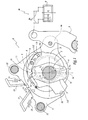
- the dobby R represented at Figures 1 to 3 comprises a main shaft 1 animated by an intermittent rotation movement, with stopping every half-turn.
- This shaft receives bearings 1a in number equal to that of the heald frames or blades of the craft.
- On each bearing 1a is mounted idler an eccentric 2 secured laterally to a plate 3.
- Around each eccentric 2 is mounted, with the interposition of a bearing 2a, a connecting rod 4 whose free end 4a is coupled to a pivoting arm 5 which ensures, thanks to a connection rods 6a, the vertical movement of the heald frame or blade 6 considered.
- This framework is very schematically represented in the figure 1 .
- the trade M thus comprises the dobby R represented on the left of the figure 1 , as well as several frames of the frame type 6, each frame being moved according to a vertical oscillations movement represented by the double arrow F 1 , by a lever 5, itself actuated by a connecting rod 4.
- X 1 denotes the longitudinal geometric axis of the shaft 1, this axis constituting the axis of rotation of this shaft.
- the shaft 1 carries a drive member 7 of elongate shape and whose central opening is substantially circular and centered on an axis X 7 .
- the central opening of the member 7 is provided with two teeth 71 engaged in longitudinal grooves of corresponding shape formed at the periphery of the shaft 1.
- the axes X 1 and X 7 are merged.
- the member 7 is integral in rotation with the shaft 1.
- the member 7 is provided with two notches 72 arranged on the same diameter D 1 of the shaft 1, symmetrical with respect to this diameter and intended to selectively receive a finger 81 of a pawl 8 articulated on an axis 9 carried by the plate 3 integral with the eccentric 2 corresponding.
- a spring 10 tends to permanently recall the finger 81 of the pawl 8 towards the shaft 1, that is to say to engage the finger 81 in one of the notches 72 when disposed opposite this finger.
- each lever 11 has a generally angled profile and is biased by a spring 13 in order to come into abutment with a shank 111 against a corresponding fixed abutment 14.
- the shank 111 of each lever 11 can be selectively controlled by a pusher (not shown) reading, as represented by the arrows 15.
- each lever 11 is provided with a spout 112 provided to cooperate with two wedging surfaces 31 and 32 formed at the periphery of the plate 3.
- the spring 13 form an elastic means which tends to engage the nose 112 of each lever 11 with one of the two wedging surfaces 31 and 32. Thanks to the spouts 112 and surfaces 31 and 32, the plate 3 can be immobilized in two positions separated by a 180 ° rotation of the shaft 1. More specifically, the plate 3 can be immobilized in the position of the figure 1 or in a position in which the surface 31 cooperates with the spout 112 of the lever 11 shown on the left of this figure, while its surface 32 cooperates with the spout 112 of the lever shown on the right of this figure.
- the springs 13 act on the levers 11 so that the nozzles 112 engage with the surfaces 31 and 32 when they arrive opposite the one of these spouts due to the rotation of the shaft 1.
- This has the effect of exerting on a tail 82 of the pawl 8 a centripetal force F 2 which rotates the pawl in the direction of the arrow F 3 to the figure 1 , against the action of the spring 10.
- the finger 81 is thus clear of the notch 72 in which it was previously introduced.
- This engagement of the nozzles 112 with the surfaces 31 and 32 has the effect of immobilizing the plate 3 angularly and with it the eccentric 2 and the connecting rod 4 which are integral in rotation of this plate.
- the member 7 can therefore be driven over a 180 ° stroke by the shaft 1, without itself driving the plate 3, the eccentric 2 and the connecting rod 4.
- the rotational movement F 4 of the member 7 around the axis X 1 is transmitted to the finger 81 at an interface I 1 through which passes a motor force F 5 of the member 7 to the finger 81
- This force is exerted by a first edge 721 of the notch 72 against which is supported a flat lateral face 811 of the finger 81.
- the interface I 1 is formed by the portions bearing the edge 721 and the face 811. It constitutes a "motor" interface for driving the pawl 8 and elements 2, 3 and 4 associated.
- the thickness of the edge 721 and the face 811 perpendicular to the plane of the figure 2 is limited by the width available for the placement of elements 7 and 2 in the division of the trade, this division being generally between 10 and 20 mm. It is therefore not possible to act on this width to increase the contact area between the edge 721 and the face 811. However, this area can be relatively small since the effort F 5 is a variable effort which is exercised while the edge 721 remains fixed relative to the face 811, when the member 7 drives the pawl 8.
- the finger 81 also carries, by a flat lateral face 812 opposite the face 811, against a second edge 722 of the notch 72, this at an interface I 2 at which a braking force F 6 is transmitted.
- the interface I 2 thus constitutes a braking interface between the pawl 8 and the member 7.
- the faces 811 and 812 and the edges 721 and 722 are shown as not being supported, which is the case in certain phases of movement due to possible functional gaps.
- the interfaces I 1 and I 2 extend over the height of the plane portions of the faces 811 and 812 and the edges 721 and 722 which are capable of coming into surface abutment against each other.
- B 1 is the bisector of faces 811 and 812.
- B 2 is the bisector of the plane portions of edges 721 and 722.
- these bisectors are merged with each other and with a radius R 1 radial to the axis X 1 and passing equidistant from the faces 811 and 812.
- the finger 81 When the force F 6 is applied, that is to say while the elements 1 and 7 are being decelerated, the finger 81 begins to be removed from the notch 72, in the direction of the arrow F 7 to the figure 2 , which induces a sliding under load of the face 812 against the edge 722, in the direction of the arrow F 8 to the figure 2 .
- the height H 1 of the orthogonal projection I ' 1 of the interface I 1 on the bisector B 1 is not increased so as not to hinder the disengagement movement F 7 of the finger 81 when it is appropriate to to extract from the notch 72 under the effect of the force F 2 .
- the performance of the extraction control remains the same when the race and the extraction rate remain unchanged.
- the performance of the extraction control is not reduced.
- the height H 2 is greater than the height H 1 . Taking into account the fact that the thickness of the parts 7 and 8 is uniform, this induces that the interface I 2 has an area greater than the interface I 1 , which allows optimized transmission of the forces at the time when the driving of the pawl 8 by the member 7 and during the release or extraction of the finger 81 relative to the notch 72.
- edges 721 and 722 of the notch 72 are generally parallel to each other and to the bisector B 2 .
- the lateral faces 811 and 812 of the finger 81 are parallel to each other and to the bisector B 1 .
- each notch 72 has a relief in the form of a rounded boss 724, formed in its central part and against which the face 813.
- the dobby is in the configuration of the figure 3 .
- the face 813 is configured to slide then on the outer radial surface 73 of the member 7 in the direction of the arrow F 9 , before the finger 81 is engaged in the notch 72 under the effect of the elastic force of spring 10, this as soon as the notch 72 reaches opposite this finger 81.
- the face 813 is substantially complementary to the surface 73 in its adjacent portion of the edge 722 of each notch.
- only part of the face 813 may be substantially complementary to the surface 73.
- the difference in the radial heights H 2 and H 1 is related to the fact that the orthogonal projection of the edge 722 on the bisector B 2 has a height h 2 greater than the height h 1 of the orthogonal projection of the edge 721 on this bisector B 2 .
- the orthogonal projections of the faces 811 and 812 on the bisector B 1 have heights h ' 1 and h' 2 substantially equal.
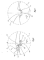
- a dobby R is partially represented. This dobby comprises elements similar to elements 2, 4, 5 and 11 to 14 of the first embodiment which are not shown.
- the drive shaft 1 of this dobby is integral in rotation with a drive disk 7 having substantially the same function as the member 7 of the first embodiment but which is generally shaped circular disc centered on the axis X 1 of rotation of the shaft 1.
- the disc 7 is provided with four teeth 71 for securing in rotation with the shaft 1 and two notches 72 diametrically opposed along a radius D 1 perpendicular to the X axis 1 of rotation of the shaft 1.
- a pawl 8 is pivotally mounted on an axis 9 carried by a plate 3, this pawl 8 being subjected to the action of a spring 10 tending to engage a finger 81 of the ratchet in one of the notches 72.
- the shaft 1 rotates clockwise at the figure 5 , as represented by the arrow F 4 , that is to say in a direction opposite to the direction of rotation of the shaft 1 to Figures 1 to 3 .
- the transmission interface of the motor force F 5 between the disk 7 and the finger 81 is respectively denoted I 1 , this interface being defined between a first flat lateral surface 811 of the finger 81 and a first edge 721 of the notch 72.
- I 2 note the braking interface between a second flat lateral face 812 of the finger 81 and a second edge 722 of the notch 72, the braking force F 6 of the finger 81 being exerted at this interface to the end of 180 ° rotation of the shaft 1.
- the orthogonal projection I ' 2 of the interface I 2 on the bisectors B 1 and B 2 has a height H 2 greater than the height H 1 of the orthogonal projection I' 1 of the interface I 1 on these bisectors.
- the orthogonal projections on the bisector B 2 of the edges 721 and 722 have substantially the same radial height, h 1 and h 2 , whereas the height h 2 of the orthogonal projection of the face 812 on the bisector B 1 is greater than the height h ' 1 of the orthogonal projection of the face 811 on this bisector B 1 .
- H 2 , h 1 , h 2 and h ' 2 are substantially equal while the values of H 1 and h' 1 are equal to and lower than the previous ones.
- the bottom 723 of the notch 72 is generally perpendicular to the edges 721 and 722, while the end face 813 of the finger 81 is inclined relative to a median radius R 1 between the faces 811 and 812 which are parallel to each other and at this radius, as well as the edges 721 and 722.
- This embodiment has the advantage that a same drive disk can be used regardless of the direction of rotation F 4 of the shaft 1. Only the pawl 8 must be adapted by a corresponding distribution of its first side face 811 and its second side face 812 which respectively define the interfaces I 1 and I 2 .
- the orthogonal projections I ' 1 and I' 2 , on the bisectors B 1 and B 2 defined as above, interfaces I 1 and I 2 , defined as above, have different heights, the height H 2 of the projection I ' 2 being greater than the height H 1 of the projection I ' 1 .
- This embodiment differs from the previous embodiment in that the end face 813 of the finger 81 is substantially complementary in shape to the bottom 723 of the notch 72.
- the heights H 2 , h 2 and h ' 2 are equal to each other, while the heights H 1 , h 1 and h' 1 are equal to each other and lower than the previous ones.
- the side faces 811 and 812 of the finger 81 are parallel to each other and to the bisector B 1
- the edges 721 and 722 of the notch 72 are parallel to each other and to the bisector B 2 .
- the member 7 of the first embodiment may be disk-shaped and the disk 7 of the second embodiment may be oblong.
- a relief of the type of the bump 724 can be provided in all embodiments to receive in support the finger 81.
- the bisectors B 1 and B 2 are combined when the finger 81 is engaged in a notch 72. However, this is not mandatory. In addition, it is not mandatory for the bisectors B 1 and B 2 to be confused with a radial radius at the axis X 1 .
- the invention has been shown with a finger 81 whose side faces 811 and 812 are flat and notches 72 whose edges 721 and 722 are straight. These faces and / or these edges may be curved, it being understood that the contact interfaces are then not strictly linear but surface based on surface pressures.
- the bisectors and the orthogonal projections of these interfaces are then defined in a manner analogous to those mentioned above.
- an average line is defined, for example a cord of an arc of a circle or a tangent in a central zone of these edges or faces, as representative of the orientation of these edges or faces. From such average lines, a bisector is defined as before.
Landscapes
- Engineering & Computer Science (AREA)
- Textile Engineering (AREA)
- Chairs For Special Purposes, Such As Reclining Chairs (AREA)
- Looms (AREA)
- Woven Fabrics (AREA)
- Catching Or Destruction (AREA)
- Transmission Devices (AREA)
Claims (10)
- Rotationsschaftmaschine für eine Webmaschine, für jeden ihrer Schäfte umfassend:- ein Schwingteil (4), das an einen Schaftrahmen (6) angekoppelt ist und einem Betätigungselement (2) zugeordnet ist und das frei drehbar auf einer Hauptwelle (1) der Schaftmaschine (R) montiert ist;- ein bewegliches Ankoppelorgan (8), das von einer mit dem Betätigungselement verbundenen Platte (3) getragen wird, wobei dieses bewegliche Organ ersten elastischen Mitteln (10) unterworfen ist, um die Winkelverbindung der Platte mit einem Antriebselement (7) zu betätigen, das drehfest mit der Hauptwelle verbunden ist und mit zwei diametral gegenüberliegenden Vertiefungen (72) zur Aufnahme eines Fingers (81) des Ankoppelorgans versehen ist, wobei der Finger geeignet ist, in Kontakt mit den Rändern (721, 722) einer Vertiefung zu kommen, in der er an einer ersten Grenzfläche (I1), die zwischen einer ersten Seitenfläche (811) des Fingers und einem ersten Rand (721) der Vertiefung definiert ist und durch die dem beweglichen Organ eine Antriebskraft (F5) zum Antrieb der Platte zur Drehung übertragen wird, und an einer zweiten Grenzfläche (I2) in Eingriff ist, die zwischen einer zweiten Seitenfläche (812) des Fingers und einem zweiten Rand (722) der Vertiefung definiert ist und durch die dem beweglichen Organ eine Kraft (F6) zum Bremsen der Platte übertragen wird,dadurch gekennzeichnet, dass die Höhe (H2) der orthogonalen Projektion (I'2) der zweiten Grenzfläche (I2) auf die Winkelhalbierende (B1) der Seitenflächen (811, 812) des Fingers (81) oder auf die Winkelhalbierende (B2) der Ränder (721, 722) der Vertiefung (72) größer ist als die Höhe (H1) der orthogonalen Projektion (I'1) der ersten Grenzfläche (I1) auf diegleiche Winkelhalbierende (B1 oder B2).
- Schaftmaschine nach Anspruch 1, dadurch gekennzeichnet, dass die Höhe (h2) der orthogonalen Projektion des zweiten Randes (722) auf die Winkelhalbierende (B2) der Ränder (721, 722) jeder Vertiefung (72) größer ist als die radiale Höhe (h1) der orthogonalen Projektion des ersten Randes (721) der Vertiefung auf dieselbe Winkelhalbierende (B2), wobei die orthogonalen Projektionen der Seitenflächen (811, 812) des Fingers (81) auf die Winkelhalbierende (B1) dieser Flächen im Wesentlichen die gleiche Höhe (h'1, h'2) hat.
- Schaftmaschine nach Anspruch 2, dadurch gekennzeichnet, dass die Endfläche (813) des Fingers (81) des beweglichen Organs (8) mindestens teilweise im Wesentlichen komplementär zu einem Bereich (73) der äußeren radialen Oberfläche des Antriebselements (7) in der Nähe des zweiten Randes (722) jeder seiner Vertiefungen (72) ist.
- Schaftmaschine nach Anspruch 1, dadurch gekennzeichnet, dass die Höhe (h'2) der orthogonalen Projektion der zweiten Seitenfläche (812) des Fingers (81) auf die Winkelhalbierende (B1) der Seitenflächen (811, 812) dieses Fingers größer als die Höhe (h'1) der orthogonalen Projektion der ersten Seitenfläche (811) des Fingers auf dieselbe Winkelhalbierende (B1) ist, wobei die orthogonalen Projektionen der Ränder (721, 722) der Vertiefungen auf die Winkelhalbierende (B2) dieser Ränder im Wesentlichen die gleiche Höhe (h1, h2) haben.
- Schaftmaschine nach Anspruch 1, dadurch gekennzeichnet, dass die Höhe (h2) der orthogonalen Projektion des zweiten Randes (722) auf die Winkelhalbierende (B2) der Ränder (721, 722) jeder Vertiefung (72) größer als die Höhe (h1) der orthogonalen Projektion des ersten Randes (721) der Vertiefung auf dieselbe Winkelhalbierende (B2) ist, während die Höhe (h'2) der orthogonalen Projektion der zweiten Seitenfläche (812) des Fingers (81) auf die Winkelhalbierende (B1) der Seitenflächen (811, 812) dieses Fingers größer ist als die Höhe (h'1) der orthogonalen Projektion seiner ersten Seitenfläche (811) auf die Winkelhalbierende (B1) dieser Flächen.
- Schaftmaschine nach Anspruch 5, dadurch gekennzeichnet, dass die Endfläche (813) des Fingers (81) im Wesentlichen komplementär zum Boden (723) der Vertiefung (72) ist.
- Schaftmaschine nach einem der vorhergehenden Ansprüche, dadurch gekennzeichnet, dass die Winkelhalbierende (B1) der ersten und zweiten Seitenfläche (811, 812) des Fingers (81) und/oder die Winkelhalbierende (B2) des ersten und zweiten Randes (721, 722) jeder Vertiefung (72) mit einem in Bezug auf die geometrische Drehachse (X1) der Antriebswelle (1) radialen Radius (R1) übereinstimmen.
- Schaftmaschine nach einem der vorhergehenden Ansprüche, dadurch gekennzeichnet, dass die erste und zweite Seitenfläche (811, 812) des Fingers (81) und der erste und zweite Rand (721, 822) jeder Vertiefung (72) im Wesentlichen parallel zu einem in Bezug auf die geometrische Drehachse (X1) der Antriebswelle (1) radialen Radius (R1) sind und mit den Winkelhalbierenden (B1, B2) dieser Flächen (811, 812) und Ränder (721, 722) übereinstimmen.
- Webmaschine (M) ausgerüstet mit einer Schaftmaschine (R) nach einem der vorhergehenden Ansprüche.
- Antriebselement (7), das zu einer Schaftmaschine nach einem der Ansprüche 1 bis 3 und 5 bis 8 gehört und vorgesehen ist, eine Platte (3) zur Drehung anzutreiben, die mit einem Betätigungselement (2) verbunden ist, das einem ersten Schwingteil (4) einer Schaftmaschine zugeordnet ist, wobei das Antriebselement mit zwei Vertiefungen (72) versehen ist, die vorgesehen sind, selektiv einen Finger (81) aufzunehmen, der zu einem beweglichen Ankoppelelement (8) gehört, das von der Platte (3) getragen wird, dadurch gekennzeichnet, dass die Höhe (h2) der orthogonalen Projektion eines Randes (722) jeder Vertiefung, der vorgesehen ist, an den Finger (81) eine Kraft (F6) zum Bremsen der Platte zu übertragen, auf die Winkelhalbierende (B2) der Ränder (721, 722) dieser Vertiefung (72) größer ist als die Höhe (h1) der orthogonalen Projektion auf dieselbe Winkelhalbierende (B2) eines Randes (721) dieser Vertiefung, der vorgesehen ist, dem Finger (81) eine Antriebskraft (F5) zum Drehantrieb der Platte zu übertragen.
Applications Claiming Priority (1)
| Application Number | Priority Date | Filing Date | Title |
|---|---|---|---|
| FR0602830A FR2899244B1 (fr) | 2006-03-31 | 2006-03-31 | Ratiere rotative, metier a tisser equipe d'une telle ratiere et element d'entrainement pour une telle ratiere |
Publications (2)
| Publication Number | Publication Date |
|---|---|
| EP1840251A1 EP1840251A1 (de) | 2007-10-03 |
| EP1840251B1 true EP1840251B1 (de) | 2009-08-19 |
Family
ID=37106958
Family Applications (1)
| Application Number | Title | Priority Date | Filing Date |
|---|---|---|---|
| EP07356036A Not-in-force EP1840251B1 (de) | 2006-03-31 | 2007-03-26 | Rotationsschaftmaschine, mit einer solchen Schaftmaschine ausgestattete Webmaschine und Antriebselement für eine solche Schaftmaschine |
Country Status (5)
| Country | Link |
|---|---|
| EP (1) | EP1840251B1 (de) |
| CN (1) | CN101046022B (de) |
| AT (1) | ATE440161T1 (de) |
| DE (1) | DE602007001990D1 (de) |
| FR (1) | FR2899244B1 (de) |
Families Citing this family (2)
| Publication number | Priority date | Publication date | Assignee | Title |
|---|---|---|---|---|
| CN101709525B (zh) * | 2009-11-19 | 2011-04-13 | 常熟纺织机械厂有限公司 | 旋转式电子多臂机的三开口开口机构 |
| FR2957366B1 (fr) * | 2010-03-12 | 2012-04-13 | Staubli Sa Ets | Ratiere rotative et metier a tisser equipe d'une telle ratiere |
Citations (1)
| Publication number | Priority date | Publication date | Assignee | Title |
|---|---|---|---|---|
| EP0768402A1 (de) * | 1995-10-06 | 1997-04-16 | FIMTEXTILE S.p.A. | Vorrichtung zum Programmieren von Rotationsschaftmaschinen im Webstühlen |
Family Cites Families (4)
| Publication number | Priority date | Publication date | Assignee | Title |
|---|---|---|---|---|
| EP0080547A1 (de) * | 1981-11-30 | 1983-06-08 | GebràDer Sulzer Aktiengesellschaft | Verfahren für den Betrieb einer Kupplungsanordnung zum Steuern der Schäfte einer Webmaschine und zugehörige Kupplungsanordnung |
| EP0109999B1 (de) * | 1982-12-03 | 1988-03-09 | GebràDer Sulzer Aktiengesellschaft | Kupplungsanordnung zum Steuern der Schäfte einer Webmaschine |
| FR2540524B1 (fr) * | 1983-02-07 | 1985-07-26 | Staubli Sa Ets | Ratiere rotative synchronisee pour metiers a tisser |
| FR2757882B1 (fr) * | 1996-12-31 | 1999-02-19 | Staubli Sa Ets | Ratiere rotative et metier a tisser equipe d'une telle ratiere |
-
2006
- 2006-03-31 FR FR0602830A patent/FR2899244B1/fr not_active Expired - Fee Related
-
2007
- 2007-03-26 AT AT07356036T patent/ATE440161T1/de not_active IP Right Cessation
- 2007-03-26 DE DE602007001990T patent/DE602007001990D1/de active Active
- 2007-03-26 EP EP07356036A patent/EP1840251B1/de not_active Not-in-force
- 2007-03-29 CN CN2007100895651A patent/CN101046022B/zh active Active
Patent Citations (1)
| Publication number | Priority date | Publication date | Assignee | Title |
|---|---|---|---|---|
| EP0768402A1 (de) * | 1995-10-06 | 1997-04-16 | FIMTEXTILE S.p.A. | Vorrichtung zum Programmieren von Rotationsschaftmaschinen im Webstühlen |
Also Published As
| Publication number | Publication date |
|---|---|
| EP1840251A1 (de) | 2007-10-03 |
| FR2899244A1 (fr) | 2007-10-05 |
| FR2899244B1 (fr) | 2008-06-13 |
| CN101046022B (zh) | 2012-02-01 |
| CN101046022A (zh) | 2007-10-03 |
| ATE440161T1 (de) | 2009-09-15 |
| DE602007001990D1 (de) | 2009-10-01 |
Similar Documents
| Publication | Publication Date | Title |
|---|---|---|
| EP1322804B1 (de) | Vorrichtung zum verbinden eines webschaftes mit einem antriebshebel und webmaschine mit einer solchen vorrichtung | |
| EP1382725B1 (de) | Rotationsschaftmaschine für Webmaschinen und Webmaschine mit einer solchen Schaftmaschine | |
| EP0851045B1 (de) | Rotationsschaftmaschine und Webmaschine mit einer solchen Schaftmaschine | |
| EP0823501B2 (de) | Verfahren und Vorrichtung zur Wahl der beweglichen Haken einer Fachbildungsvorrichtung sowie Jacquardwebmaschine | |
| EP1845181B1 (de) | Rotationsschaftmaschine, eine solche Schaftmaschine umfassende Webmaschine und Verfahren zur Steuerung einer solchen Schaftmaschine | |
| EP0036830A1 (de) | Rotationsschaftmaschinen für Webmaschinen | |
| EP0851046B1 (de) | Rotationsschaftmaschine und Webmaschine mit einer solchen Schaftmaschine | |
| FR2596425A1 (fr) | Ratiere rotative pour machines a tisser | |
| FR2463213A1 (fr) | Ratiere a unites de levage rotatives | |
| EP1840251A1 (de) | Rotationsschaftmaschine, mit einer solchen Schaftmaschine ausgestattete Webmaschine und Antriebselement für eine solche Schaftmaschine | |
| EP2492381B1 (de) | Abstandhalter und Unterelement zur Trennung von Hebeln einer Fachbildungsmaschine, Maschine, die ein solches Unterelement umfasst und entsprechendes Montageverfahren | |
| FR2636394A1 (fr) | Mecanisme de transmission a cames pour produire un pivotement periodique d'un dispositif de pivotement notamment pour machine rotative d'impression de feuilles | |
| FR2540524A1 (fr) | Ratiere rotative synchronisee pour metiers a tisser | |
| EP1401746A2 (de) | Vorrichtung zum zuführen von teilen zu einer maschine | |
| FR2931796A1 (fr) | Systeme simplifie de commande de calage d'une pale d'helice d'un turbomoteur pour aeronef | |
| EP2239358B1 (de) | Montagevorrichtung, Komplex aus zwei zusammengesetzten Teilen mit Hilfe dieser Vorrichtung und Webschaft einer Schaftmaschine zur Fächerbildung, die einen solchen Komplex umfasst | |
| EP2365116B1 (de) | Rotationsschaftmaschine und mit einer solchen Schaftmaschine ausgestattete Webmaschine | |
| EP3203326B1 (de) | Konvertierungsmechanismus für einer rotationsbewegung in jeder drehrichtung in einer bewegung mit einer einzelen bewegung richtung. | |
| EP1619279B1 (de) | Fachbildemechanismus, Dreipositions-Fachbildemechanismus und Webmaschine mit einem solchen Fachbildungsmechanismus | |
| EP0159245B1 (de) | Scheibenwischanlage | |
| EP0099842B1 (de) | Rücklaufeinrichtungen von Schaftmaschinen | |
| EP1111106B1 (de) | Rotationsschaftmaschine für Webmaschinen und Webmaschine mit einer solchen Schaftmaschine | |
| FR2630068A1 (fr) | Dispositif d'entrainement d'un balai d'essuie-glace permettant une mise en position de retrait | |
| EP4467695B1 (de) | Rotationsschaftmaschine und webmaschine mit einer solchen schaftmaschine | |
| FR2463326A1 (fr) | Frein a disque a rattrapage automatique d'usure |
Legal Events
| Date | Code | Title | Description |
|---|---|---|---|
| PUAI | Public reference made under article 153(3) epc to a published international application that has entered the european phase |
Free format text: ORIGINAL CODE: 0009012 |
|
| AK | Designated contracting states |
Kind code of ref document: A1 Designated state(s): AT BE BG CH CY CZ DE DK EE ES FI FR GB GR HU IE IS IT LI LT LU LV MC MT NL PL PT RO SE SI SK TR |
|
| AX | Request for extension of the european patent |
Extension state: AL BA HR MK YU |
|
| 17P | Request for examination filed |
Effective date: 20080204 |
|
| AKX | Designation fees paid |
Designated state(s): AT BE BG CH CY CZ DE DK EE ES FI FR GB GR HU IE IS IT LI LT LU LV MC MT NL PL PT RO SE SI SK TR |
|
| 17Q | First examination report despatched |
Effective date: 20080814 |
|
| GRAP | Despatch of communication of intention to grant a patent |
Free format text: ORIGINAL CODE: EPIDOSNIGR1 |
|
| GRAS | Grant fee paid |
Free format text: ORIGINAL CODE: EPIDOSNIGR3 |
|
| GRAA | (expected) grant |
Free format text: ORIGINAL CODE: 0009210 |
|
| AK | Designated contracting states |
Kind code of ref document: B1 Designated state(s): AT BE BG CH CY CZ DE DK EE ES FI FR GB GR HU IE IS IT LI LT LU LV MC MT NL PL PT RO SE SI SK TR |
|
| REG | Reference to a national code |
Ref country code: GB Ref legal event code: FG4D Free format text: NOT ENGLISH |
|
| REG | Reference to a national code |
Ref country code: CH Ref legal event code: EP |
|
| REG | Reference to a national code |
Ref country code: IE Ref legal event code: FG4D |
|
| REF | Corresponds to: |
Ref document number: 602007001990 Country of ref document: DE Date of ref document: 20091001 Kind code of ref document: P |
|
| LTIE | Lt: invalidation of european patent or patent extension |
Effective date: 20090819 |
|
| PG25 | Lapsed in a contracting state [announced via postgrant information from national office to epo] |
Ref country code: AT Free format text: LAPSE BECAUSE OF FAILURE TO SUBMIT A TRANSLATION OF THE DESCRIPTION OR TO PAY THE FEE WITHIN THE PRESCRIBED TIME-LIMIT Effective date: 20090819 Ref country code: FI Free format text: LAPSE BECAUSE OF FAILURE TO SUBMIT A TRANSLATION OF THE DESCRIPTION OR TO PAY THE FEE WITHIN THE PRESCRIBED TIME-LIMIT Effective date: 20090819 Ref country code: IS Free format text: LAPSE BECAUSE OF FAILURE TO SUBMIT A TRANSLATION OF THE DESCRIPTION OR TO PAY THE FEE WITHIN THE PRESCRIBED TIME-LIMIT Effective date: 20091219 Ref country code: SE Free format text: LAPSE BECAUSE OF FAILURE TO SUBMIT A TRANSLATION OF THE DESCRIPTION OR TO PAY THE FEE WITHIN THE PRESCRIBED TIME-LIMIT Effective date: 20090819 Ref country code: ES Free format text: LAPSE BECAUSE OF FAILURE TO SUBMIT A TRANSLATION OF THE DESCRIPTION OR TO PAY THE FEE WITHIN THE PRESCRIBED TIME-LIMIT Effective date: 20091130 Ref country code: LT Free format text: LAPSE BECAUSE OF FAILURE TO SUBMIT A TRANSLATION OF THE DESCRIPTION OR TO PAY THE FEE WITHIN THE PRESCRIBED TIME-LIMIT Effective date: 20090819 |
|
| NLV1 | Nl: lapsed or annulled due to failure to fulfill the requirements of art. 29p and 29m of the patents act | ||
| PG25 | Lapsed in a contracting state [announced via postgrant information from national office to epo] |
Ref country code: PL Free format text: LAPSE BECAUSE OF FAILURE TO SUBMIT A TRANSLATION OF THE DESCRIPTION OR TO PAY THE FEE WITHIN THE PRESCRIBED TIME-LIMIT Effective date: 20090819 Ref country code: SI Free format text: LAPSE BECAUSE OF FAILURE TO SUBMIT A TRANSLATION OF THE DESCRIPTION OR TO PAY THE FEE WITHIN THE PRESCRIBED TIME-LIMIT Effective date: 20090819 Ref country code: NL Free format text: LAPSE BECAUSE OF FAILURE TO SUBMIT A TRANSLATION OF THE DESCRIPTION OR TO PAY THE FEE WITHIN THE PRESCRIBED TIME-LIMIT Effective date: 20090819 Ref country code: LV Free format text: LAPSE BECAUSE OF FAILURE TO SUBMIT A TRANSLATION OF THE DESCRIPTION OR TO PAY THE FEE WITHIN THE PRESCRIBED TIME-LIMIT Effective date: 20090819 |
|
| REG | Reference to a national code |
Ref country code: IE Ref legal event code: FD4D |
|
| PG25 | Lapsed in a contracting state [announced via postgrant information from national office to epo] |
Ref country code: CY Free format text: LAPSE BECAUSE OF FAILURE TO SUBMIT A TRANSLATION OF THE DESCRIPTION OR TO PAY THE FEE WITHIN THE PRESCRIBED TIME-LIMIT Effective date: 20090819 Ref country code: PT Free format text: LAPSE BECAUSE OF FAILURE TO SUBMIT A TRANSLATION OF THE DESCRIPTION OR TO PAY THE FEE WITHIN THE PRESCRIBED TIME-LIMIT Effective date: 20091221 Ref country code: BG Free format text: LAPSE BECAUSE OF FAILURE TO SUBMIT A TRANSLATION OF THE DESCRIPTION OR TO PAY THE FEE WITHIN THE PRESCRIBED TIME-LIMIT Effective date: 20091119 |
|
| PG25 | Lapsed in a contracting state [announced via postgrant information from national office to epo] |
Ref country code: EE Free format text: LAPSE BECAUSE OF FAILURE TO SUBMIT A TRANSLATION OF THE DESCRIPTION OR TO PAY THE FEE WITHIN THE PRESCRIBED TIME-LIMIT Effective date: 20090819 Ref country code: RO Free format text: LAPSE BECAUSE OF FAILURE TO SUBMIT A TRANSLATION OF THE DESCRIPTION OR TO PAY THE FEE WITHIN THE PRESCRIBED TIME-LIMIT Effective date: 20090819 Ref country code: IE Free format text: LAPSE BECAUSE OF FAILURE TO SUBMIT A TRANSLATION OF THE DESCRIPTION OR TO PAY THE FEE WITHIN THE PRESCRIBED TIME-LIMIT Effective date: 20090819 Ref country code: DK Free format text: LAPSE BECAUSE OF FAILURE TO SUBMIT A TRANSLATION OF THE DESCRIPTION OR TO PAY THE FEE WITHIN THE PRESCRIBED TIME-LIMIT Effective date: 20090819 |
|
| PG25 | Lapsed in a contracting state [announced via postgrant information from national office to epo] |
Ref country code: SK Free format text: LAPSE BECAUSE OF FAILURE TO SUBMIT A TRANSLATION OF THE DESCRIPTION OR TO PAY THE FEE WITHIN THE PRESCRIBED TIME-LIMIT Effective date: 20090819 |
|
| PLBE | No opposition filed within time limit |
Free format text: ORIGINAL CODE: 0009261 |
|
| STAA | Information on the status of an ep patent application or granted ep patent |
Free format text: STATUS: NO OPPOSITION FILED WITHIN TIME LIMIT |
|
| 26N | No opposition filed |
Effective date: 20100520 |
|
| PG25 | Lapsed in a contracting state [announced via postgrant information from national office to epo] |
Ref country code: GR Free format text: LAPSE BECAUSE OF FAILURE TO SUBMIT A TRANSLATION OF THE DESCRIPTION OR TO PAY THE FEE WITHIN THE PRESCRIBED TIME-LIMIT Effective date: 20091120 Ref country code: MC Free format text: LAPSE BECAUSE OF NON-PAYMENT OF DUE FEES Effective date: 20100331 |
|
| PG25 | Lapsed in a contracting state [announced via postgrant information from national office to epo] |
Ref country code: IT Free format text: LAPSE BECAUSE OF NON-PAYMENT OF DUE FEES Effective date: 20100326 |
|
| PG25 | Lapsed in a contracting state [announced via postgrant information from national office to epo] |
Ref country code: MT Free format text: LAPSE BECAUSE OF FAILURE TO SUBMIT A TRANSLATION OF THE DESCRIPTION OR TO PAY THE FEE WITHIN THE PRESCRIBED TIME-LIMIT Effective date: 20090819 |
|
| GBPC | Gb: european patent ceased through non-payment of renewal fee |
Effective date: 20110326 |
|
| PG25 | Lapsed in a contracting state [announced via postgrant information from national office to epo] |
Ref country code: GB Free format text: LAPSE BECAUSE OF NON-PAYMENT OF DUE FEES Effective date: 20110326 |
|
| PG25 | Lapsed in a contracting state [announced via postgrant information from national office to epo] |
Ref country code: HU Free format text: LAPSE BECAUSE OF FAILURE TO SUBMIT A TRANSLATION OF THE DESCRIPTION OR TO PAY THE FEE WITHIN THE PRESCRIBED TIME-LIMIT Effective date: 20100220 Ref country code: LU Free format text: LAPSE BECAUSE OF NON-PAYMENT OF DUE FEES Effective date: 20100326 |
|
| REG | Reference to a national code |
Ref country code: FR Ref legal event code: PLFP Year of fee payment: 10 |
|
| REG | Reference to a national code |
Ref country code: FR Ref legal event code: PLFP Year of fee payment: 11 |
|
| REG | Reference to a national code |
Ref country code: FR Ref legal event code: PLFP Year of fee payment: 12 |
|
| PGFP | Annual fee paid to national office [announced via postgrant information from national office to epo] |
Ref country code: DE Payment date: 20200327 Year of fee payment: 14 |
|
| PGFP | Annual fee paid to national office [announced via postgrant information from national office to epo] |
Ref country code: CZ Payment date: 20200310 Year of fee payment: 14 |
|
| PGFP | Annual fee paid to national office [announced via postgrant information from national office to epo] |
Ref country code: FR Payment date: 20200325 Year of fee payment: 14 |
|
| PGFP | Annual fee paid to national office [announced via postgrant information from national office to epo] |
Ref country code: CH Payment date: 20200401 Year of fee payment: 14 |
|
| REG | Reference to a national code |
Ref country code: DE Ref legal event code: R119 Ref document number: 602007001990 Country of ref document: DE |
|
| PG25 | Lapsed in a contracting state [announced via postgrant information from national office to epo] |
Ref country code: CZ Free format text: LAPSE BECAUSE OF NON-PAYMENT OF DUE FEES Effective date: 20210326 |
|
| REG | Reference to a national code |
Ref country code: CH Ref legal event code: PL |
|
| PG25 | Lapsed in a contracting state [announced via postgrant information from national office to epo] |
Ref country code: DE Free format text: LAPSE BECAUSE OF NON-PAYMENT OF DUE FEES Effective date: 20211001 Ref country code: FR Free format text: LAPSE BECAUSE OF NON-PAYMENT OF DUE FEES Effective date: 20210331 Ref country code: CH Free format text: LAPSE BECAUSE OF NON-PAYMENT OF DUE FEES Effective date: 20210331 Ref country code: LI Free format text: LAPSE BECAUSE OF NON-PAYMENT OF DUE FEES Effective date: 20210331 |
|
| PGFP | Annual fee paid to national office [announced via postgrant information from national office to epo] |
Ref country code: TR Payment date: 20230314 Year of fee payment: 17 Ref country code: IT Payment date: 20230321 Year of fee payment: 17 Ref country code: BE Payment date: 20230327 Year of fee payment: 17 |
|
| REG | Reference to a national code |
Ref country code: BE Ref legal event code: MM Effective date: 20240331 |
|
| PG25 | Lapsed in a contracting state [announced via postgrant information from national office to epo] |
Ref country code: BE Free format text: LAPSE BECAUSE OF NON-PAYMENT OF DUE FEES Effective date: 20240331 |
|
| PG25 | Lapsed in a contracting state [announced via postgrant information from national office to epo] |
Ref country code: BE Free format text: LAPSE BECAUSE OF NON-PAYMENT OF DUE FEES Effective date: 20240331 |
|
| PG25 | Lapsed in a contracting state [announced via postgrant information from national office to epo] |
Ref country code: IT Free format text: LAPSE BECAUSE OF NON-PAYMENT OF DUE FEES Effective date: 20240326 |
|
| PG25 | Lapsed in a contracting state [announced via postgrant information from national office to epo] |
Ref country code: TR Free format text: LAPSE BECAUSE OF NON-PAYMENT OF DUE FEES Effective date: 20240326 |