EP1840268A1 - Fraiseuse pour un engin, engin tout comme unité d'engrenage pour une fraiseuse - Google Patents
Fraiseuse pour un engin, engin tout comme unité d'engrenage pour une fraiseuse Download PDFInfo
- Publication number
- EP1840268A1 EP1840268A1 EP07102726A EP07102726A EP1840268A1 EP 1840268 A1 EP1840268 A1 EP 1840268A1 EP 07102726 A EP07102726 A EP 07102726A EP 07102726 A EP07102726 A EP 07102726A EP 1840268 A1 EP1840268 A1 EP 1840268A1
- Authority
- EP
- European Patent Office
- Prior art keywords
- milling
- support ring
- support
- rotatably mounted
- tube
- Prior art date
- Legal status (The legal status is an assumption and is not a legal conclusion. Google has not performed a legal analysis and makes no representation as to the accuracy of the status listed.)
- Granted
Links
Images



Classifications
-
- E—FIXED CONSTRUCTIONS
- E01—CONSTRUCTION OF ROADS, RAILWAYS, OR BRIDGES
- E01C—CONSTRUCTION OF, OR SURFACES FOR, ROADS, SPORTS GROUNDS, OR THE LIKE; MACHINES OR AUXILIARY TOOLS FOR CONSTRUCTION OR REPAIR
- E01C23/00—Auxiliary devices or arrangements for constructing, repairing, reconditioning, or taking-up road or like surfaces
- E01C23/06—Devices or arrangements for working the finished surface; Devices for repairing or reconditioning the surface of damaged paving; Recycling in place or on the road
- E01C23/08—Devices or arrangements for working the finished surface; Devices for repairing or reconditioning the surface of damaged paving; Recycling in place or on the road for roughening or patterning; for removing the surface down to a predetermined depth high spots or material bonded to the surface, e.g. markings; for maintaining earth roads, clay courts or like surfaces by means of surface working tools, e.g. scarifiers, levelling blades
- E01C23/085—Devices or arrangements for working the finished surface; Devices for repairing or reconditioning the surface of damaged paving; Recycling in place or on the road for roughening or patterning; for removing the surface down to a predetermined depth high spots or material bonded to the surface, e.g. markings; for maintaining earth roads, clay courts or like surfaces by means of surface working tools, e.g. scarifiers, levelling blades using power-driven tools, e.g. vibratory tools
- E01C23/088—Rotary tools, e.g. milling drums
-
- B—PERFORMING OPERATIONS; TRANSPORTING
- B28—WORKING CEMENT, CLAY, OR STONE
- B28D—WORKING STONE OR STONE-LIKE MATERIALS
- B28D1/00—Working stone or stone-like materials, e.g. brick, concrete or glass, not provided for elsewhere; Machines, devices, tools therefor
- B28D1/18—Working stone or stone-like materials, e.g. brick, concrete or glass, not provided for elsewhere; Machines, devices, tools therefor by milling, e.g. channelling by means of milling tools
- B28D1/186—Tools therefor, e.g. having exchangeable cutter bits
-
- Y—GENERAL TAGGING OF NEW TECHNOLOGICAL DEVELOPMENTS; GENERAL TAGGING OF CROSS-SECTIONAL TECHNOLOGIES SPANNING OVER SEVERAL SECTIONS OF THE IPC; TECHNICAL SUBJECTS COVERED BY FORMER USPC CROSS-REFERENCE ART COLLECTIONS [XRACs] AND DIGESTS
- Y10—TECHNICAL SUBJECTS COVERED BY FORMER USPC
- Y10T—TECHNICAL SUBJECTS COVERED BY FORMER US CLASSIFICATION
- Y10T29/00—Metal working
- Y10T29/49—Method of mechanical manufacture
- Y10T29/49718—Repairing
- Y10T29/49721—Repairing with disassembling
- Y10T29/4973—Replacing of defective part
-
- Y—GENERAL TAGGING OF NEW TECHNOLOGICAL DEVELOPMENTS; GENERAL TAGGING OF CROSS-SECTIONAL TECHNOLOGIES SPANNING OVER SEVERAL SECTIONS OF THE IPC; TECHNICAL SUBJECTS COVERED BY FORMER USPC CROSS-REFERENCE ART COLLECTIONS [XRACs] AND DIGESTS
- Y10—TECHNICAL SUBJECTS COVERED BY FORMER USPC
- Y10T—TECHNICAL SUBJECTS COVERED BY FORMER US CLASSIFICATION
- Y10T29/00—Metal working
- Y10T29/49—Method of mechanical manufacture
- Y10T29/49826—Assembling or joining
Definitions
- the invention relates to a milling drum according to the preamble of claim 1, or a construction machine according to claim 24, and a gear unit for a milling drum according to claim 25.
- the milling drum has a replaceable milling tube, wherein the axis of the milling tube, supported by a support ring on a support ring receptacle of a rotatably mounted, coupled with a milling drum drive body.
- the support ring is seated with a predetermined play on the support ring receptacle, wherein in the gap between the support ring and support ring receiving dirty water, dust and fine-grained parts of the road surface can penetrate, in particular due to relative movements between the support ring and the support ring receiving, resulting from the milling process.
- the capillary action of the clearance increases this effect, so that contaminated water and fine particles penetrate into the fit.
- conically shaped support surfaces have not proven to be practical, because on the one hand they can set too strong and on the other hand have too much radial play when the réelleschiebende milling roller is too short. Therefore, with a conical support surface, accuracy of positioning the conical support ring and the support ring receptacle in a range of +/- 1 mm would be required to enable operation at all, with the problem that a cone connection can seize remains.
- the invention is therefore based on the object of simplifying the assembly and disassembly of the milling tube in milling drums with replaceable milling tubes, in construction machines with milling drums and gear units that drive a milling drum.
- the invention provides in an advantageous manner that the support ring and the support ring receptacle of the rotatably mounted body a plurality of Fräswalzenachse concentrically extending, complementary support surfaces having different Stütz Vietnamese bemessern which are arranged axially one after another with decreasing diameters in the withdrawal direction.
- the step-shaped design of the support surfaces of the support ring and the support ring receiving can be achieved without reducing the total surface area of the support surface, that the milling tube must be deducted only by the amount of width of a step to bring the support ring out of engagement with the support ring receptacle. For example, with a five-fold gradation, the distance required to separate the support surfaces from each other can be reduced to one-fifth of the total axial length of the support surface.
- At least three, preferably five support surfaces are arranged axially one behind the other.
- the length of the axially successively arranged support surfaces is 5 to 40 mm, preferably 10 to 20 mm. In this way, a load bearing support surface for a milling tube of a milling drum is created.
- the length of a support surface may be the same in the axial direction. This has the advantage that when removing all support surfaces are simultaneously disengaged.
- the length of the support surfaces in the axial direction may be different, and preferably such that the length of the support surfaces decreases with decreasing support circle diameter. This has the advantage that the support surfaces, in particular during assembly, are not all engaged at the same time, whereby the assembly can be facilitated.
- the support surfaces of the support ring relative to the support surfaces of the support ring receiving axially offset in the withdrawal direction of the milling tube, such that annular chambers are formed at the step transitions.
- the annular chambers can be used advantageously to be filled with a corrosion inhibitor or a lubricant.
- the annular chambers may be connected to an injection channel, via which a corrosion protection agent and / or a lubricant can be injected.
- the injection channel may have a nipple for injecting grease.
- the support surfaces may be coated with a sliding layer to facilitate assembly and disassembly.
- the support ring receptacle may consist of a one-piece ring or be integral with the rotatably mounted body.
- the one-piece support ring receptacle can be pushed, for example, on the rotatably mounted body and fixed there axially.
- the support ring receiver can be integral with the rotatably mounted body, whereby the number of components can be reduced.
- the support ring receptacle consists of a multi-part, preferably two-part ring which can be mounted on the rotatably mounted body.
- a support ring receptacle is advantageous if a support ring receptacle is not pushed onto the rotatably mounted body.
- the support ring receptacle is axially immovably mounted on the rotatably mounted body and forms a loose bearing.
- the support ring receptacle can be fixed axially at different locations on the rotatably mounted body.
- the rotatably mounted body is a roller base body for supporting the milling tube and / or a driven housing of a gear unit of the milling roller drive.
- the axis of the milling tube can be stored in a two-sided storage on the one hand in a removable side wall and on the other hand supported by means of the support ring on the support ring receptacle of the rotatably mounted body, the milling tube after removal of the side wall of the support ring receptacle of the rotatably mounted body in the withdrawal direction deductible is.
- roller base body is coupled to the milling drum drive and supports the side wall facing the end of the milling tube.
- the axial support surfaces arranged one behind the other with different support circle diameter at the step transitions have a chamfer running, for example, at 45 °.
- This chamfer makes it easier to center the milling tube during assembly, which simplifies assembly.
- a bevel running at 45 ° is used.
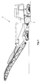
- a road construction machine 1 in which a milling tube quick-change system can be used.
- the road construction machine is a road milling machine which generally has a machine frame on which an engine and a control station are mounted.
- the self-propelled road construction machine has height-adjustable, mounted on the machine frame lifting columns on which support wheels or crawler tracks are mounted.
- the milling drum 2 is located under the machine frame in a roller box 9, which laterally has the side walls 13, 15. By the reference numeral 7, the sectional contour of the tools located on the milling drum 2 is indicated.
- the processed from the milling drum 2 material is dropped in a conventional manner on a first conveyor belt or conveyed to a second, height-adjustable and pivotable conveyor belt.
- a milling drum 2 is rotatably supported between orthogonal to the axis 20 of the milling drum 2 extending side walls 13, 15 of the roller box 9 and is driven by a mounted on the drive side side wall 13 drive means 16 and a gear unit 17.
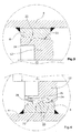
- the milling drum 2 shown in Fig. 2 consists of a one-piece milling tube 4, which is removably attached to a roller body 19.
- the roller body 19 is in turn attached to the output housing 21 of the transmission unit 17.
- the roller main body 19 is arranged axially next to the drive housing 21 and transmits the torque of the gear unit 17 in the manner of a reduction gear to the respective inserted milling tube 4th
- the milling drum drive 16 preferably consists of a belt drive.
- the milling tube is screwed in Fig. 2 via an annular flange 23 to the roller body 19, which in turn is rotatably mounted in the removable side wall 15.
- On the milling drum drive 16 facing side of the milling tube 4 a rotatably connected to the milling tube 4 support ring 8 is arranged, which cooperates with a seated on the driven housing 21 support ring receptacle 12.
- the support ring 8 and the support ring receptacle 12 have a plurality of mutually complementary to Fräswalzenachse 20 mutually complementary support surfaces 22, 24 with different support circle diameters, which are arranged axially one after another with decreasing in the direction of the side wall 15 diameter.
- the axial length of the support surfaces 22, 24 is 15 mm in the illustrated embodiments, but may vary depending on the diameter of the milling drum 2 between 5 and 40 mm, preferably between 10 and 20 mm.
- the exemplary embodiments show that the axial length of all supporting surfaces 22, 24 is the same. However, they may also have a different length, and preferably such that the length of the support surfaces 22, 24 decreases with decreasing Stauer réelle bemesser.
- annular chambers 25 may be filled with a corrosion inhibitor and / or a lubricant.
- an injection channel 26 may be provided, over which, as shown in Fig. 3, at least three annular chambers 25, e.g. be supplied with grease via a grease nipple 28.
- the support surfaces 22, 24 may be coated with a sliding layer to facilitate the assembly and disassembly of the milling tube 4.
- the support ring receptacle 12 may consist of a one-piece ring, as shown in FIG. 2 can be seen, or may also be integral with the output housing 21 of the gear unit 17, as shown in the embodiments of FIGS. 9 and 10.
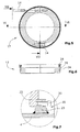
- the support ring receptacle 12 consists of a multi-part ring, two-part in Figs. 5 and 6, mounted on a rotatably mounted body, e.g. the output housing 21 of the transmission unit 17 can be mounted.
- the support ring receptacle 12 may also be axially movably mounted on a rotatably mounted body, as in the embodiments of FIGS. 2 to 4 is possible, or axially immovably mounted on the rotatably mounted body, as shown in the embodiments of FIGS. 9 and 10.
- Fig. 5 fastening screws 14 can be seen, with which the support ring receptacle 12 is mounted on a rotatably mounted body.
- the rotatable body can also consist of a ring or connection flange and not necessarily an output housing 21 or a roller base 19 must be.
- FIG. 6 is a section along the line VI-VI in FIG. 5, wherein the sectional profile extends through the injection channel 26.
- FIG. 7 shows a side view of the support ring receptacle 12, along the line VII-VII in FIG. 5.
- a mechanical Abdschreib worn 29 is shown, in which by means of screws 30, the milling tube 4 can be deducted from its storage on the support ring receptacle.
- the screws 30 are screwed against the mounting flange 23, whereby the milling tube 4 of the milling drum 2 can be deducted.
- a 45 ° extending chamfer 32 is provided which facilitates the mounting and centering of the milling tube 4.
- Corresponding chamfers 32 are also provided between the support surfaces 24 of the support ring 8.
- the support surfaces 22, 24 are concentric with the Fräswalzenachse 20, preferably coaxially.
- the height of a step between the support surfaces 22, 24 is for example 1 to 4 mm, wherein a step jump of 2 mm has proven to be particularly advantageous.
Landscapes
- Engineering & Computer Science (AREA)
- Mechanical Engineering (AREA)
- Mining & Mineral Resources (AREA)
- Architecture (AREA)
- Civil Engineering (AREA)
- Structural Engineering (AREA)
- Road Repair (AREA)
- Milling Processes (AREA)
- Rolls And Other Rotary Bodies (AREA)
- Crushing And Grinding (AREA)
- Road Paving Machines (AREA)
- Disintegrating Or Milling (AREA)
- Crushing And Pulverization Processes (AREA)
- Reduction Rolling/Reduction Stand/Operation Of Reduction Machine (AREA)
Applications Claiming Priority (1)
| Application Number | Priority Date | Filing Date | Title |
|---|---|---|---|
| DE102006015506A DE102006015506B3 (de) | 2006-03-31 | 2006-03-31 | Fräswalze für eine Baumaschine, Baumaschine sowie Getriebeeinheit für eine Fräswalze |
Publications (2)
| Publication Number | Publication Date |
|---|---|
| EP1840268A1 true EP1840268A1 (fr) | 2007-10-03 |
| EP1840268B1 EP1840268B1 (fr) | 2009-09-16 |
Family
ID=38254991
Family Applications (1)
| Application Number | Title | Priority Date | Filing Date |
|---|---|---|---|
| EP07102726A Active EP1840268B1 (fr) | 2006-03-31 | 2007-02-20 | Fraiseuse pour un engin, engin et unité d'engrenage pour une fraiseuse |
Country Status (9)
| Country | Link |
|---|---|
| US (2) | US7901011B2 (fr) |
| EP (1) | EP1840268B1 (fr) |
| JP (1) | JP4781304B2 (fr) |
| CN (1) | CN101046085B (fr) |
| AT (1) | ATE443183T1 (fr) |
| AU (1) | AU2007201080B2 (fr) |
| BR (1) | BRPI0701984B1 (fr) |
| DE (2) | DE102006015506B3 (fr) |
| RU (1) | RU2345192C1 (fr) |
Cited By (2)
| Publication number | Priority date | Publication date | Assignee | Title |
|---|---|---|---|---|
| DE102009059064A1 (de) | 2009-12-18 | 2011-06-22 | Wirtgen GmbH, 53578 | Selbstfahrende Straßenfräsmachine |
| EP4563747A1 (fr) | 2023-11-28 | 2025-06-04 | Pronar Sp.zo.o. | Machine pour la stabilisation du sol et des agregats avec un rouleau de broyage |
Families Citing this family (22)
| Publication number | Priority date | Publication date | Assignee | Title |
|---|---|---|---|---|
| DE102006015506B3 (de) * | 2006-03-31 | 2007-11-08 | Wirtgen Gmbh | Fräswalze für eine Baumaschine, Baumaschine sowie Getriebeeinheit für eine Fräswalze |
| DE102009014729B3 (de) * | 2009-03-25 | 2010-11-04 | Wirtgen Gmbh | Auswerfer für eine Straßenfräsmaschine oder dergleichen |
| US8469456B2 (en) | 2009-03-25 | 2013-06-25 | Wirtgen Gmbh | Ejector unit for a road milling machine or the like |
| CN102678114A (zh) * | 2011-03-12 | 2012-09-19 | 刘素华 | 滚耙料装置 |
| DE102012103440B4 (de) * | 2012-04-19 | 2016-01-21 | Wirtgen Gmbh | Kufensegment für einen Kantenschutz einer Straßenfräsmaschine und Kantenschutz für eine Straßenfräsmaschine |
| DE102012008252B4 (de) * | 2012-04-25 | 2026-02-12 | Bomag Gmbh | Fräseinrichtung für eine Bodenfräsmaschine, Fräswalze für eine solche Fräseinrichtung und Bodenfräsmaschine mit einer solchen Fräseinrichtung |
| DE102013208638B4 (de) * | 2013-05-10 | 2018-01-11 | Wirtgen Gmbh | Straßenfräsmaschine, sowie Verfahren zur Montage einer fliegend gelagerten Fräswalze |
| DE102015209740A1 (de) * | 2014-12-30 | 2016-06-30 | Wirtgen Gmbh | Selbstfahrende Strassenfräsmaschine zum Bearbeiten von Strassenoberflächen, sowie Verfahren zum Bearbeiten von Strassenoberflächen mit einer Strassenfräsmaschine |
| CN104963267B (zh) * | 2015-07-24 | 2017-01-25 | 关士锋 | 一种可稳定运行的智能化道路施工装置 |
| CN107268409B (zh) * | 2015-07-24 | 2020-02-07 | 百年建设集团有限公司 | 一种液压升降的道路施工装置 |
| CN105099073B (zh) * | 2015-07-24 | 2017-07-28 | 乌兰察布市金桥公路工程有限责任公司 | 一种可精确调节的智能化道路施工装置 |
| DE102016113251A1 (de) * | 2015-10-27 | 2017-04-27 | Wirtgen Gmbh | Fräsmaschine und Verfahren zum Betrieb einer Fräsmaschine |
| US10584450B2 (en) * | 2017-03-23 | 2020-03-10 | Caterpillar Paving Products Inc. | Rotary mixer |
| DE102017208775A1 (de) * | 2017-05-23 | 2018-11-29 | Wirtgen Gmbh | Bodenbearbeitungsmaschine, deren Arbeitsvorrichtung mit einem Bord-Aktuator aus ihrer Betriebsposition verlagerbar ist |
| EP3636838B1 (fr) | 2017-05-23 | 2021-07-21 | Wirtgen GmbH | Machine de traitement de sol et procédé de pression d'un dispositif de travail d'un machine de traitement de sol |
| DE102017220518A1 (de) * | 2017-05-23 | 2018-11-29 | Wirtgen Gmbh | Bodenbearbeitungsmaschine mit einer durch zentrale Schraubanordnung axial mit hohem Anzugsmoment positionssicherbaren drehbaren Arbeitsvorrichtung und Verfahren zum Herstellen und Lösen einer solchen Sicherung |
| DE102020105391B3 (de) | 2020-02-28 | 2021-03-18 | Wirtgen Gmbh | Bodenbearbeitungsmaschine mit Formschluss zwischen rotierender Arbeitsbaugruppe und dessen Drehlager |
| US11834798B2 (en) | 2021-10-06 | 2023-12-05 | Caterpillar Paving Products Inc. | System for transferring torque from driveshafts to milling drums |
| US11674273B2 (en) * | 2021-10-06 | 2023-06-13 | Caterpillar Paving Products Inc. | Milling drum with alignment interface |
| US11585053B1 (en) | 2021-10-13 | 2023-02-21 | Caterpillar Paving Products Inc. | Milling machine with drum bearing assembly |
| US12486626B2 (en) | 2023-07-19 | 2025-12-02 | Caterpillar Paving Products Inc. | Quick change rotor alignment feature |
| US20250027280A1 (en) * | 2023-07-19 | 2025-01-23 | Caterpillar Paving Products Inc. | Serviceable milling drum load support |
Citations (2)
| Publication number | Priority date | Publication date | Assignee | Title |
|---|---|---|---|---|
| US5722789A (en) * | 1994-07-29 | 1998-03-03 | Wirtgen America, Inc. | Multi-width cutter |
| WO2004005623A1 (fr) * | 2002-07-09 | 2004-01-15 | Wirtgen Gmbh | Fraiseuse de route automotrice |
Family Cites Families (8)
| Publication number | Priority date | Publication date | Assignee | Title |
|---|---|---|---|---|
| DE2836395C2 (de) * | 1978-08-19 | 1980-07-17 | Gebr. Heller Maschinenfabrik Gmbh, 7440 Nuertingen | Satzfräser |
| EP0089386A1 (fr) * | 1982-03-19 | 1983-09-28 | Losenhausen Maschinenbau AG& Co Kommanditgesellschaft | Rouleau vibrant à cylindre divisé |
| US4755001A (en) * | 1986-09-08 | 1988-07-05 | Gilbert Jerry F | Road planar |
| JP2530075Y2 (ja) * | 1989-05-16 | 1997-03-26 | 小松造機株式会社 | 路面切削機械の切削ドラム取付装置 |
| DE19504495A1 (de) * | 1995-02-12 | 1996-08-22 | Wirtgen Gmbh | Maschine zur Erneuerung von Fahrbahnen |
| DE19932396A1 (de) * | 1999-07-14 | 2001-02-01 | Wirtgen Gmbh | Baumaschine sowie Fräswalze |
| CN2594299Y (zh) * | 2002-09-29 | 2003-12-24 | 兖州恒升机械有限公司 | 路面铣刨机 |
| DE102006015506B3 (de) * | 2006-03-31 | 2007-11-08 | Wirtgen Gmbh | Fräswalze für eine Baumaschine, Baumaschine sowie Getriebeeinheit für eine Fräswalze |
-
2006
- 2006-03-31 DE DE102006015506A patent/DE102006015506B3/de not_active Expired - Fee Related
-
2007
- 2007-02-20 EP EP07102726A patent/EP1840268B1/fr active Active
- 2007-02-20 AT AT07102726T patent/ATE443183T1/de active
- 2007-02-20 DE DE502007001518T patent/DE502007001518D1/de active Active
- 2007-03-13 AU AU2007201080A patent/AU2007201080B2/en not_active Ceased
- 2007-03-23 JP JP2007076587A patent/JP4781304B2/ja active Active
- 2007-03-29 CN CN200710089561.3A patent/CN101046085B/zh active Active
- 2007-03-29 US US11/727,989 patent/US7901011B2/en active Active
- 2007-03-30 RU RU2007111855/03A patent/RU2345192C1/ru active
- 2007-03-30 BR BRPI0701984-0A patent/BRPI0701984B1/pt not_active IP Right Cessation
-
2011
- 2011-01-25 US US13/013,016 patent/US8118369B2/en active Active
Patent Citations (2)
| Publication number | Priority date | Publication date | Assignee | Title |
|---|---|---|---|---|
| US5722789A (en) * | 1994-07-29 | 1998-03-03 | Wirtgen America, Inc. | Multi-width cutter |
| WO2004005623A1 (fr) * | 2002-07-09 | 2004-01-15 | Wirtgen Gmbh | Fraiseuse de route automotrice |
Cited By (8)
| Publication number | Priority date | Publication date | Assignee | Title |
|---|---|---|---|---|
| DE102009059064A1 (de) | 2009-12-18 | 2011-06-22 | Wirtgen GmbH, 53578 | Selbstfahrende Straßenfräsmachine |
| EP2336426A2 (fr) | 2009-12-18 | 2011-06-22 | Wirtgen GmbH | Machine automobile à fraiser la chaussée |
| CN102102338A (zh) * | 2009-12-18 | 2011-06-22 | 维特根有限公司 | 自动道路磨铣机 |
| DE102009059064B4 (de) * | 2009-12-18 | 2012-04-26 | Wirtgen Gmbh | Selbstfahrende Straßenfräsmaschine |
| CN102102338B (zh) * | 2009-12-18 | 2013-07-24 | 维特根有限公司 | 自动道路磨铣机 |
| US8985702B2 (en) | 2009-12-18 | 2015-03-24 | Wirtgen Gmbh | Automotive road milling machine |
| US9399843B2 (en) | 2009-12-18 | 2016-07-26 | Wirtgen Gmbh | Automotive road milling machine |
| EP4563747A1 (fr) | 2023-11-28 | 2025-06-04 | Pronar Sp.zo.o. | Machine pour la stabilisation du sol et des agregats avec un rouleau de broyage |
Also Published As
| Publication number | Publication date |
|---|---|
| ATE443183T1 (de) | 2009-10-15 |
| AU2007201080A1 (en) | 2007-10-18 |
| DE102006015506B3 (de) | 2007-11-08 |
| BRPI0701984B1 (pt) | 2018-01-30 |
| RU2345192C1 (ru) | 2009-01-27 |
| AU2007201080B2 (en) | 2009-07-16 |
| CN101046085A (zh) | 2007-10-03 |
| US20070228806A1 (en) | 2007-10-04 |
| US7901011B2 (en) | 2011-03-08 |
| EP1840268B1 (fr) | 2009-09-16 |
| US8118369B2 (en) | 2012-02-21 |
| DE502007001518D1 (de) | 2009-10-29 |
| JP2007270611A (ja) | 2007-10-18 |
| US20110115278A1 (en) | 2011-05-19 |
| BRPI0701984A (pt) | 2008-07-15 |
| JP4781304B2 (ja) | 2011-09-28 |
| CN101046085B (zh) | 2011-02-09 |
| RU2007111855A (ru) | 2008-10-10 |
Similar Documents
| Publication | Publication Date | Title |
|---|---|---|
| EP1840268B1 (fr) | Fraiseuse pour un engin, engin et unité d'engrenage pour une fraiseuse | |
| EP1194651B2 (fr) | Engin de construction et cylindre de fraisage | |
| DE102012008252B4 (de) | Fräseinrichtung für eine Bodenfräsmaschine, Fräswalze für eine solche Fräseinrichtung und Bodenfräsmaschine mit einer solchen Fräseinrichtung | |
| DE102007050466A1 (de) | Extruder mit mindestens einem Planetwalzenmodul | |
| DE19739315C1 (de) | Räummaschine | |
| DE102020105391B3 (de) | Bodenbearbeitungsmaschine mit Formschluss zwischen rotierender Arbeitsbaugruppe und dessen Drehlager | |
| DE69111364T2 (de) | Verfahren und Werkzeug zum Anbringen von Gewindeeinsatz. | |
| DE202010018091U1 (de) | Vorrichtung zur Bearbeitung einer Zylinderbohrung mit geometrischbestimmter Schneide | |
| EP0156762A1 (fr) | Foret à couronne | |
| EP3034699B1 (fr) | Dispositif de travail | |
| DE4028841C1 (en) | Mounting for vehicle drive coupling - has threaded spindle with spigot supported in shaped sleeve | |
| DE102010010431B4 (de) | Verfahren zur Wiederaufarbeitung der verschlissenen Oberfläche von Mahlwalzen einer Gutbettwalzenmühle | |
| EP4012105B1 (fr) | Procédé de montage d'une roue de fraisage d'un engin de creusement | |
| EP1572386B1 (fr) | Laminoir comprenant des moyens pour le changement des cylindres | |
| DE202011004123U1 (de) | Teilbare Spindelwelle | |
| EP0169393A1 (fr) | Dispositif pour la production de forages d'une section transversale inaccessible | |
| DE68904577T2 (de) | Stellvorrichtung fuer ein eisenbahnfahrzeug auf einer raddrehbank. | |
| EP0344117B1 (fr) | Procédé et dispositif pour laminer des rainures dans des queues d'outils | |
| DE19910541C1 (de) | Vorrichtung zur Montage, Sicherung und Demontage eines auf einer fliegend gelagerten Walzenwelle verspannten Walzrings | |
| EP0943735B1 (fr) | Appareil de fraisage | |
| DE112009001413B4 (de) | Walzmaschine zum Umformen von metallischen und/oder eisenhaltigen Werkstücken mit verstellbaren Walzen | |
| EP2420350A2 (fr) | Dispositif d'avance et machine, notamment machine à écorcer | |
| DE8709361U1 (de) | Schneidwerkzeug zum Herstellen einer Durchbohrung in einer mit Stahl bewehrten Betonwand | |
| DE10232489A1 (de) | Selbstfahrende Straßenfräsmaschine | |
| EP4357532B1 (fr) | Procédé d'insertion d'une tige filetée dans un support, et système de vissage correspondant |
Legal Events
| Date | Code | Title | Description |
|---|---|---|---|
| PUAI | Public reference made under article 153(3) epc to a published international application that has entered the european phase |
Free format text: ORIGINAL CODE: 0009012 |
|
| AK | Designated contracting states |
Kind code of ref document: A1 Designated state(s): AT BE BG CH CY CZ DE DK EE ES FI FR GB GR HU IE IS IT LI LT LU LV MC NL PL PT RO SE SI SK TR |
|
| AX | Request for extension of the european patent |
Extension state: AL BA HR MK YU |
|
| 17P | Request for examination filed |
Effective date: 20071117 |
|
| AKX | Designation fees paid |
Designated state(s): AT BE BG CH CY CZ DE DK EE ES FI FR GB GR HU IE IS IT LI LT LU LV MC NL PL PT RO SE SI SK TR |
|
| GRAP | Despatch of communication of intention to grant a patent |
Free format text: ORIGINAL CODE: EPIDOSNIGR1 |
|
| GRAC | Information related to communication of intention to grant a patent modified |
Free format text: ORIGINAL CODE: EPIDOSCIGR1 |
|
| GRAS | Grant fee paid |
Free format text: ORIGINAL CODE: EPIDOSNIGR3 |
|
| GRAA | (expected) grant |
Free format text: ORIGINAL CODE: 0009210 |
|
| AK | Designated contracting states |
Kind code of ref document: B1 Designated state(s): AT BE BG CH CY CZ DE DK EE ES FI FR GB GR HU IE IS IT LI LT LU LV MC NL PL PT RO SE SI SK TR |
|
| REG | Reference to a national code |
Ref country code: GB Ref legal event code: FG4D Free format text: NOT ENGLISH |
|
| RAP2 | Party data changed (patent owner data changed or rights of a patent transferred) |
Owner name: WIRTGEN GMBH |
|
| REG | Reference to a national code |
Ref country code: CH Ref legal event code: EP |
|
| REG | Reference to a national code |
Ref country code: IE Ref legal event code: FG4D |
|
| REF | Corresponds to: |
Ref document number: 502007001518 Country of ref document: DE Date of ref document: 20091029 Kind code of ref document: P |
|
| NLT2 | Nl: modifications (of names), taken from the european patent patent bulletin |
Owner name: WIRTGEN GMBH Effective date: 20090930 |
|
| PG25 | Lapsed in a contracting state [announced via postgrant information from national office to epo] |
Ref country code: FI Free format text: LAPSE BECAUSE OF FAILURE TO SUBMIT A TRANSLATION OF THE DESCRIPTION OR TO PAY THE FEE WITHIN THE PRESCRIBED TIME-LIMIT Effective date: 20090916 Ref country code: SE Free format text: LAPSE BECAUSE OF FAILURE TO SUBMIT A TRANSLATION OF THE DESCRIPTION OR TO PAY THE FEE WITHIN THE PRESCRIBED TIME-LIMIT Effective date: 20090916 Ref country code: LT Free format text: LAPSE BECAUSE OF FAILURE TO SUBMIT A TRANSLATION OF THE DESCRIPTION OR TO PAY THE FEE WITHIN THE PRESCRIBED TIME-LIMIT Effective date: 20090916 |
|
| LTIE | Lt: invalidation of european patent or patent extension |
Effective date: 20090916 |
|
| PG25 | Lapsed in a contracting state [announced via postgrant information from national office to epo] |
Ref country code: PL Free format text: LAPSE BECAUSE OF FAILURE TO SUBMIT A TRANSLATION OF THE DESCRIPTION OR TO PAY THE FEE WITHIN THE PRESCRIBED TIME-LIMIT Effective date: 20090916 Ref country code: SI Free format text: LAPSE BECAUSE OF FAILURE TO SUBMIT A TRANSLATION OF THE DESCRIPTION OR TO PAY THE FEE WITHIN THE PRESCRIBED TIME-LIMIT Effective date: 20090916 Ref country code: NL Free format text: LAPSE BECAUSE OF FAILURE TO SUBMIT A TRANSLATION OF THE DESCRIPTION OR TO PAY THE FEE WITHIN THE PRESCRIBED TIME-LIMIT Effective date: 20090916 Ref country code: LV Free format text: LAPSE BECAUSE OF FAILURE TO SUBMIT A TRANSLATION OF THE DESCRIPTION OR TO PAY THE FEE WITHIN THE PRESCRIBED TIME-LIMIT Effective date: 20090916 |
|
| NLV1 | Nl: lapsed or annulled due to failure to fulfill the requirements of art. 29p and 29m of the patents act | ||
| PG25 | Lapsed in a contracting state [announced via postgrant information from national office to epo] |
Ref country code: CY Free format text: LAPSE BECAUSE OF FAILURE TO SUBMIT A TRANSLATION OF THE DESCRIPTION OR TO PAY THE FEE WITHIN THE PRESCRIBED TIME-LIMIT Effective date: 20090916 |
|
| REG | Reference to a national code |
Ref country code: IE Ref legal event code: FD4D |
|
| PG25 | Lapsed in a contracting state [announced via postgrant information from national office to epo] |
Ref country code: ES Free format text: LAPSE BECAUSE OF FAILURE TO SUBMIT A TRANSLATION OF THE DESCRIPTION OR TO PAY THE FEE WITHIN THE PRESCRIBED TIME-LIMIT Effective date: 20091227 Ref country code: RO Free format text: LAPSE BECAUSE OF FAILURE TO SUBMIT A TRANSLATION OF THE DESCRIPTION OR TO PAY THE FEE WITHIN THE PRESCRIBED TIME-LIMIT Effective date: 20090916 Ref country code: IE Free format text: LAPSE BECAUSE OF FAILURE TO SUBMIT A TRANSLATION OF THE DESCRIPTION OR TO PAY THE FEE WITHIN THE PRESCRIBED TIME-LIMIT Effective date: 20090916 Ref country code: PT Free format text: LAPSE BECAUSE OF FAILURE TO SUBMIT A TRANSLATION OF THE DESCRIPTION OR TO PAY THE FEE WITHIN THE PRESCRIBED TIME-LIMIT Effective date: 20100118 Ref country code: CZ Free format text: LAPSE BECAUSE OF FAILURE TO SUBMIT A TRANSLATION OF THE DESCRIPTION OR TO PAY THE FEE WITHIN THE PRESCRIBED TIME-LIMIT Effective date: 20090916 Ref country code: EE Free format text: LAPSE BECAUSE OF FAILURE TO SUBMIT A TRANSLATION OF THE DESCRIPTION OR TO PAY THE FEE WITHIN THE PRESCRIBED TIME-LIMIT Effective date: 20090916 Ref country code: IS Free format text: LAPSE BECAUSE OF FAILURE TO SUBMIT A TRANSLATION OF THE DESCRIPTION OR TO PAY THE FEE WITHIN THE PRESCRIBED TIME-LIMIT Effective date: 20100116 |
|
| PG25 | Lapsed in a contracting state [announced via postgrant information from national office to epo] |
Ref country code: SK Free format text: LAPSE BECAUSE OF FAILURE TO SUBMIT A TRANSLATION OF THE DESCRIPTION OR TO PAY THE FEE WITHIN THE PRESCRIBED TIME-LIMIT Effective date: 20090916 |
|
| PLBE | No opposition filed within time limit |
Free format text: ORIGINAL CODE: 0009261 |
|
| STAA | Information on the status of an ep patent application or granted ep patent |
Free format text: STATUS: NO OPPOSITION FILED WITHIN TIME LIMIT |
|
| PG25 | Lapsed in a contracting state [announced via postgrant information from national office to epo] |
Ref country code: DK Free format text: LAPSE BECAUSE OF FAILURE TO SUBMIT A TRANSLATION OF THE DESCRIPTION OR TO PAY THE FEE WITHIN THE PRESCRIBED TIME-LIMIT Effective date: 20090916 |
|
| 26N | No opposition filed |
Effective date: 20100617 |
|
| BERE | Be: lapsed |
Owner name: WIRTGEN G.M.B.H. Effective date: 20100228 |
|
| PG25 | Lapsed in a contracting state [announced via postgrant information from national office to epo] |
Ref country code: GR Free format text: LAPSE BECAUSE OF FAILURE TO SUBMIT A TRANSLATION OF THE DESCRIPTION OR TO PAY THE FEE WITHIN THE PRESCRIBED TIME-LIMIT Effective date: 20091217 Ref country code: MC Free format text: LAPSE BECAUSE OF NON-PAYMENT OF DUE FEES Effective date: 20100301 |
|
| PG25 | Lapsed in a contracting state [announced via postgrant information from national office to epo] |
Ref country code: BE Free format text: LAPSE BECAUSE OF NON-PAYMENT OF DUE FEES Effective date: 20100228 |
|
| PGRI | Patent reinstated in contracting state [announced from national office to epo] |
Ref country code: IT Effective date: 20110501 |
|
| REG | Reference to a national code |
Ref country code: CH Ref legal event code: PL |
|
| PG25 | Lapsed in a contracting state [announced via postgrant information from national office to epo] |
Ref country code: CH Free format text: LAPSE BECAUSE OF NON-PAYMENT OF DUE FEES Effective date: 20110228 Ref country code: LI Free format text: LAPSE BECAUSE OF NON-PAYMENT OF DUE FEES Effective date: 20110228 |
|
| PG25 | Lapsed in a contracting state [announced via postgrant information from national office to epo] |
Ref country code: BG Free format text: LAPSE BECAUSE OF FAILURE TO SUBMIT A TRANSLATION OF THE DESCRIPTION OR TO PAY THE FEE WITHIN THE PRESCRIBED TIME-LIMIT Effective date: 20090916 Ref country code: HU Free format text: LAPSE BECAUSE OF FAILURE TO SUBMIT A TRANSLATION OF THE DESCRIPTION OR TO PAY THE FEE WITHIN THE PRESCRIBED TIME-LIMIT Effective date: 20100317 Ref country code: LU Free format text: LAPSE BECAUSE OF NON-PAYMENT OF DUE FEES Effective date: 20100220 |
|
| PG25 | Lapsed in a contracting state [announced via postgrant information from national office to epo] |
Ref country code: TR Free format text: LAPSE BECAUSE OF FAILURE TO SUBMIT A TRANSLATION OF THE DESCRIPTION OR TO PAY THE FEE WITHIN THE PRESCRIBED TIME-LIMIT Effective date: 20090916 |
|
| REG | Reference to a national code |
Ref country code: AT Ref legal event code: MM01 Ref document number: 443183 Country of ref document: AT Kind code of ref document: T Effective date: 20120220 |
|
| PG25 | Lapsed in a contracting state [announced via postgrant information from national office to epo] |
Ref country code: AT Free format text: LAPSE BECAUSE OF NON-PAYMENT OF DUE FEES Effective date: 20120220 |
|
| REG | Reference to a national code |
Ref country code: FR Ref legal event code: PLFP Year of fee payment: 9 |
|
| REG | Reference to a national code |
Ref country code: FR Ref legal event code: PLFP Year of fee payment: 10 |
|
| REG | Reference to a national code |
Ref country code: FR Ref legal event code: PLFP Year of fee payment: 11 |
|
| REG | Reference to a national code |
Ref country code: FR Ref legal event code: PLFP Year of fee payment: 12 |
|
| P01 | Opt-out of the competence of the unified patent court (upc) registered |
Effective date: 20230525 |
|
| PGFP | Annual fee paid to national office [announced via postgrant information from national office to epo] |
Ref country code: GB Payment date: 20260219 Year of fee payment: 20 |
|
| PGFP | Annual fee paid to national office [announced via postgrant information from national office to epo] |
Ref country code: DE Payment date: 20260217 Year of fee payment: 20 |
|
| PGFP | Annual fee paid to national office [announced via postgrant information from national office to epo] |
Ref country code: IT Payment date: 20260227 Year of fee payment: 20 |
|
| PGFP | Annual fee paid to national office [announced via postgrant information from national office to epo] |
Ref country code: FR Payment date: 20260219 Year of fee payment: 20 |