EP1840293A2 - Panneau en béton renforcé et méthode de fabrication - Google Patents
Panneau en béton renforcé et méthode de fabrication Download PDFInfo
- Publication number
- EP1840293A2 EP1840293A2 EP20070103972 EP07103972A EP1840293A2 EP 1840293 A2 EP1840293 A2 EP 1840293A2 EP 20070103972 EP20070103972 EP 20070103972 EP 07103972 A EP07103972 A EP 07103972A EP 1840293 A2 EP1840293 A2 EP 1840293A2
- Authority
- EP
- European Patent Office
- Prior art keywords
- net
- slab
- previous
- concrete
- slab according
- Prior art date
- Legal status (The legal status is an assumption and is not a legal conclusion. Google has not performed a legal analysis and makes no representation as to the accuracy of the status listed.)
- Withdrawn
Links
- 239000000463 material Substances 0.000 title claims abstract description 15
- 238000000034 method Methods 0.000 title claims description 11
- 238000004519 manufacturing process Methods 0.000 title claims description 10
- 239000011159 matrix material Substances 0.000 claims abstract description 33
- 230000003014 reinforcing effect Effects 0.000 claims abstract description 23
- 238000011161 development Methods 0.000 claims abstract description 7
- 239000000203 mixture Substances 0.000 claims description 23
- 239000010410 layer Substances 0.000 claims description 19
- 238000003780 insertion Methods 0.000 claims description 11
- 230000037431 insertion Effects 0.000 claims description 11
- 239000004372 Polyvinyl alcohol Substances 0.000 claims description 6
- 235000019422 polyvinyl alcohol Nutrition 0.000 claims description 6
- 229920002451 polyvinyl alcohol Polymers 0.000 claims description 6
- 239000002344 surface layer Substances 0.000 claims description 6
- 229920003043 Cellulose fiber Polymers 0.000 claims description 4
- 238000005520 cutting process Methods 0.000 claims description 4
- -1 polypropylene Polymers 0.000 claims description 4
- 239000004743 Polypropylene Substances 0.000 claims description 3
- 229920003023 plastic Polymers 0.000 claims description 3
- 239000004033 plastic Substances 0.000 claims description 3
- 229920001155 polypropylene Polymers 0.000 claims description 3
- 150000001875 compounds Chemical class 0.000 claims description 2
- 238000001035 drying Methods 0.000 claims description 2
- 235000011194 food seasoning agent Nutrition 0.000 claims description 2
- 238000002360 preparation method Methods 0.000 claims description 2
- 230000001464 adherent effect Effects 0.000 claims 1
- 238000003825 pressing Methods 0.000 claims 1
- 239000010425 asbestos Substances 0.000 description 8
- 229910052895 riebeckite Inorganic materials 0.000 description 8
- 239000010408 film Substances 0.000 description 6
- 239000004568 cement Substances 0.000 description 5
- XLYOFNOQVPJJNP-UHFFFAOYSA-N water Substances O XLYOFNOQVPJJNP-UHFFFAOYSA-N 0.000 description 5
- 238000013459 approach Methods 0.000 description 2
- 239000007795 chemical reaction product Substances 0.000 description 2
- 230000006835 compression Effects 0.000 description 2
- 238000007906 compression Methods 0.000 description 2
- 239000002184 metal Substances 0.000 description 2
- 229920000642 polymer Polymers 0.000 description 2
- 239000007787 solid Substances 0.000 description 2
- 239000000126 substance Substances 0.000 description 2
- 238000005303 weighing Methods 0.000 description 2
- OKTJSMMVPCPJKN-UHFFFAOYSA-N Carbon Chemical compound [C] OKTJSMMVPCPJKN-UHFFFAOYSA-N 0.000 description 1
- 229920000271 Kevlar® Polymers 0.000 description 1
- 239000004698 Polyethylene Substances 0.000 description 1
- 239000011398 Portland cement Substances 0.000 description 1
- 230000002159 abnormal effect Effects 0.000 description 1
- 239000000654 additive Substances 0.000 description 1
- 239000011230 binding agent Substances 0.000 description 1
- 229910052799 carbon Inorganic materials 0.000 description 1
- 230000000694 effects Effects 0.000 description 1
- 239000003365 glass fiber Substances 0.000 description 1
- 239000011396 hydraulic cement Substances 0.000 description 1
- 239000004761 kevlar Substances 0.000 description 1
- 239000002245 particle Substances 0.000 description 1
- 229920000573 polyethylene Polymers 0.000 description 1
- 230000002787 reinforcement Effects 0.000 description 1
- 229910021487 silica fume Inorganic materials 0.000 description 1
- 238000012360 testing method Methods 0.000 description 1
- 239000010409 thin film Substances 0.000 description 1
- 238000009941 weaving Methods 0.000 description 1
- 238000004804 winding Methods 0.000 description 1
Images


Classifications
-
- E—FIXED CONSTRUCTIONS
- E04—BUILDING
- E04C—STRUCTURAL ELEMENTS; BUILDING MATERIALS
- E04C2/00—Building elements of relatively thin form for the construction of parts of buildings, e.g. sheet materials, slabs, or panels
- E04C2/30—Building elements of relatively thin form for the construction of parts of buildings, e.g. sheet materials, slabs, or panels characterised by the shape or structure
- E04C2/32—Building elements of relatively thin form for the construction of parts of buildings, e.g. sheet materials, slabs, or panels characterised by the shape or structure formed of corrugated or otherwise indented sheet-like material; composed of such layers with or without layers of flat sheet-like material
-
- B—PERFORMING OPERATIONS; TRANSPORTING
- B28—WORKING CEMENT, CLAY, OR STONE
- B28B—SHAPING CLAY OR OTHER CERAMIC COMPOSITIONS; SHAPING SLAG; SHAPING MIXTURES CONTAINING CEMENTITIOUS MATERIAL, e.g. PLASTER
- B28B1/00—Producing shaped prefabricated articles from the material
- B28B1/52—Producing shaped prefabricated articles from the material specially adapted for producing articles from mixtures containing fibres, e.g. asbestos cement
- B28B1/527—Producing shaped prefabricated articles from the material specially adapted for producing articles from mixtures containing fibres, e.g. asbestos cement by delivering the materials on a rotating drum, e.g. a sieve drum, from which the materials are picked up by a felt
-
- B—PERFORMING OPERATIONS; TRANSPORTING
- B28—WORKING CEMENT, CLAY, OR STONE
- B28B—SHAPING CLAY OR OTHER CERAMIC COMPOSITIONS; SHAPING SLAG; SHAPING MIXTURES CONTAINING CEMENTITIOUS MATERIAL, e.g. PLASTER
- B28B23/00—Arrangements specially adapted for the production of shaped articles with elements wholly or partly embedded in the moulding material; Production of reinforced objects
- B28B23/0006—Arrangements specially adapted for the production of shaped articles with elements wholly or partly embedded in the moulding material; Production of reinforced objects the reinforcement consisting of aligned, non-metal reinforcing elements
-
- E—FIXED CONSTRUCTIONS
- E04—BUILDING
- E04D—ROOF COVERINGS; SKY-LIGHTS; GUTTERS; ROOF-WORKING TOOLS
- E04D3/00—Roof covering by making use of flat or curved slabs or stiff sheets
- E04D3/24—Roof covering by making use of flat or curved slabs or stiff sheets with special cross-section, e.g. with corrugations on both sides, with ribs, flanges, or the like
- E04D3/26—Roof covering by making use of flat or curved slabs or stiff sheets with special cross-section, e.g. with corrugations on both sides, with ribs, flanges, or the like of concrete or ceramics
Definitions
- the present invention relates to a reinforced slab of concrete material and to a method for manufacturing such slab.
- the subject reinforced slab falls within the field of concrete prefabricated buildings for the building industry and can be advantageously used in the making of treadable building roofs, in particular industrial warehouses.
- slabs having different profiles have long been known, consisting of a concrete matrix charge with short dispersed fibres, of inorganic or organic nature.
- the concrete matrix was charged with asbestos fibres for obtaining an end product known as "concrete asbestos slab” on the market.
- asbestos fibres for obtaining an end product known as "concrete asbestos slab” on the market.
- the concrete matrix is charged with cellulose fibres and plastic polymers (for example polyvinylalcohol) for obtaining an end product known as asbestos cement on the market.
- These slabs are formed by overlapping sheets of a mixture of concrete material and fibres.
- the sheets are formed and overlapped to one another in a special forming machine, in the field known as Hatscheck machine.
- the forming machine comprises a series of picking cylinders operating in a succession, each picking into a basin containing the mixture of concrete material and fibres.
- the mixture lays on the cylinder surface forming an even film, while part of the excess water falls back into the basin.
- the films that progressively form on the picking cylinders are pulled away continuously by a first conveyor belt that transfers them to a revolving forming roll.
- the films meet suction cases that act below the belt compacting the film and reducing the water contents.
- the films leave the first conveyor belt and adhere to the outer surface of the forming roll overlapping to each other. In this way a multilayer is formed on the revolving forming roll with progressively increasing thickness.
- the roll rotation is continued until a multilayer of fixed thickness is obtained, which undergoes compression by the effect of the contrast between forming cylinder and control roll.
- the multilayer is cut along a generatrix of the roll and then transferred to a second conveyor belt where it takes a plane configuration.
- the multilayer sheet is then laid inside a shaped die where it takes the final shape of the slab and is finally left to dry.
- asbestos cement slabs with corrugated profile are made with this technique, intended for making building roofs.
- the reinforcing elements are in the form of tapes, straps or plaited threads, of metal or plastic material, and are buried in the concrete matrix along the longitudinal development of the multilayer. Normally after the slab forming the reinforcing elements are arranged at the depressions of the corrugated profile.
- the concrete matrix maintains a sufficient cohesion level for ensuring adhesion between the matrix and the reinforcing elements.
- the damaged matrix keeps its consistency. This allows the reinforcing elements to hold the broken parts avoiding the forming of tears.
- the object of the present invention is to eliminate the disadvantages of the mentioned prior art by providing a reinforced slab of concrete material which should be safe in the event of damages also with ambient humidity values below 10%.
- Another object of the present invention is to provide a reinforced slab of concrete material which should be simple and inexpensive to manufacture.
- FIG. 1 shows a perspective view of a reinforced slab according to the invention, with some parts removed for highlighting the presence of a reinforcing net
- FIG. 1 shows a section view of a reinforced slab shown in Figure 1;
- Figure 3 shows a detail of the reinforcing net shown in Figure 1;
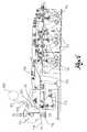
- FIG. 4 shows a side view of a machine for forming reinforced slabs according to the invention.
- Figure 5 shows a schematic view of a detail of the machined of Figure 4 relating to the means for introducing the net shown in Figure 1.
- reference numeral 1 globally denotes the reinforced slab of concrete material object of the present invention.
- the above slab 1 can advantageously be used for making treadable building roofs, in particular industrial warehouses.
- Slab 1 according to the invention comprises a base concrete matrix 10 obtained by overlapping multiple layers 11 of a concrete material mixture.
- concrete material it is herein understood in general a mixture of inert particles and hydraulic binders.
- the latter in particular may comprise hydraulic cement of the Portland type.
- the concrete material mixture is of the type used for producing the so-called asbestos cement, or charged with short dispersed fibres, organic and/or inorganic, in particular a mixture of cellulose fibres and polyvinylalcohol.
- reinforcing elements 20 are buried into the concrete matrix 10 arranged between two layers 11.
- Such reinforcing elements 20 comprise at least one net 20, which substantially extends to the entire the surface development of slab 1, as can be seen in Figure 1.
- slab 1 may be provided with multiple nets 20 arranged between different pairs of layers of the concrete matrix 10.
- a slab 1 according to the invention in the event of damage ensures the safety of people thereon in any ambient humidity condition.
- net 20 substantially serves for keeping slab 1 adhering in the event of breakage or partial yields, holding the portions of concrete matrix that may have detached from the rest of slab 1.
- net 20 acts as "safety net” preventing at least the fall of any people present on slab 1 and of the heavy body that has caused the breakage of slab 1.
- net 20 is made of polypropylene, suitably treated with antialkali compounds so that net 20 is not chemically deteriorated by the concrete mixture.
- polymers suitable for the use may be used, such as polyvinylalcohol, polyethylene, polypropylene, kevlar, carbon fibres, glass fibres.
- the meshes of net 20 have sides of length L comprised within the range between 6 and 35 mm, preferably between 8 and 12 mm. These dimensions of the mesh allow the concrete mixture to evenly cross net 20 during the slab manufacturing steps, allowing the top layers of slab 1 to closely adhere to the bottom ones.
- net 20 is formed by weaving of thread-like elements 21 having a thickness s comprised within the range between 0.5 and 1.2 mm.
- Titre T of these elements 21 is comprised within the range between 1700/2 and 1100/4 dtex.
- the titre is an indirect measure of the thickness (or diameter) of a thread-like element and is expressed as weight of the thread-like element in grams by 1,000 linear metres (Tex) or by 10,000 linear metres (dTex).
- net 20 in se has a weight comprised within the range between 60 and 110 g/m2.
- net 20 offers a resistance to tensile stress comprised within the range between 80 and 200 daN/5cm and an elongation comprised within the range between 15 and 25 %. These values apply both in the warp and in the weft direction. These values are sufficient for supporting at the same time the weight of a damaged portion of concrete matrix and the weight of a person. In particular, the ultimate elongation value of the warp is very important, since such reinforcement intervenes after the breakage of the slab matrix and can absorb the kinetic energy of the body upon the impact on the slab itself.
- net 20 is buried into the concrete matrix 10, arranged between two layers 11.
- net 20 is arranged so as to be closer to one of the two surface layers that define the two faces of slab 1. In particular it is arranged so as to be in contact with one of the two surface layers. Net 20 is therefore decentralised relative to the median plane M of slab 1, as can be seen in Figure 2.
- the two faces of slab 1 can be distinguished from one another.
- the face closer to net 20 shall be identified hereinafter as reinforced face 10', whereas the other face shall be identified as non-reinforced face 10".
- net 20 is right in the zone of slab 1 which is most subject to tensile stress. In this way net 20 can carry out a safety function as well as a more structural function.
- slabs 1 according to the invention whose results have fully confirmed the effective structural action of net 20.
- a corrugated slab of asbestos cement in normal ambient conditions should withstand the collision with a bag weighing 50 kg falling from a height of 1.20 m.
- Slabs 1 according to the invention have withstood the collision of a bag weighing 50 kg fallen from a height of even more than 2 m in conditions of limited humidity of the slabs equal to 4 - 5%, without damages.
- net 20 Functionally, thanks to the decentralised arrangement of net 20 most of the concrete matrix is arranged above net 20 itself. Only the surface layer corresponding to the reinforced face 10' (or optionally in addition also the layer adjacent thereto) is arranged under net 20. In the event of breakage of slab 1 and of concurrent detachment between layers 11, net 20 is therefore capable of mechanically supporting the entire matrix 10, with the exception of the bottom surface layer. Therefore, the portion of concrete matrix that in the event of damage of slab 1 could optionally fall is limited to the bottom surface layer only (less than one millimetre thick).
- slab 1 has a typical corrugated profile defined by a succession of longitudinal bumps 12 and depressions 13.
- net 20 is oriented inside the concrete matrix 10 so that at the end of the forming of the corrugated slab the thread-like elements that form the net are arranged substantially parallel and perpendicular to the longitudinal development direction of bumps 12 and depressions 13. In this way net 20 can more easily adapt to the corrugated shape of the slab, preventing the onset of internal tensions that could weaken slab 1 itself.
- slab 1 according to the invention is made using a Hatscheck forming machine on in se known type.
- the method for manufacturing the reinforced slab 1 according to the invention envisages an initial step of preparation (a) of a concrete mixture, charged with a mixture of short fibres, organic and/or inorganic.
- the solid substances that make up the concrete mixture are the following ones, with the relevant percentages by weight: polyvinylalcohol fibres (PVA) between 1.5 and 3%; cellulose fibres between 2 and 5 %; microsilica between 2 and 7%; Portland cement 3.25 between 65 and 85%; inert additives between 20 and 30%.
- PVA polyvinylalcohol fibres
- cellulose fibres between 2 and 5 %
- microsilica between 2 and 7%
- Portland cement 3.25 between 65 and 85%
- inert additives between 20 and 30%.
- the method then provides a step (b) of making a multilayer for subsequent overlapping of layers of the above mixture.
- This step provides the use of a Hatscheck forming machine, schematically illustrated in Figure 4.
- the machine comprises: one more basins 111 for containing the concrete mixture arranged in a succession; a picking cylinder 112 for each basin 111; a first conveyor belt 113 that slides by a first branch in contact with the picking cylinders 112; a revolving forming roll 114 with annexed control cylinder 116; one or more suction cases 115 arranged at the first conveyor belt 113; and a second conveyor belt 119.
- the concrete mixture lays on the surface of the revolving picking cylinders 112 forming an even and thin film, whereas part of the excess water falls into basins 11.
- the films that progressively from on cylinders 112 are removed by the first conveyor belt 113, where they overlap to those coming from the other picking cylinders 112 up to forming a sheet (corresponding to a layer).
- the sheet thus formed, travelling on the first conveyor belt meets the suction cases 115 and is compacted, losing part of its water content.
- the sheet leaves the first conveyor belt 113 and adheres to the outer surface of the forming roll 114 overlapping to the sheets already wound on the roll.
- slab 1 is given by the overlapping of six - seven layers each having a thickness of about 0.8-1.2 mm.
- the method provides a step (c) of cutting the multilayer at a generatrix of the forming roll 114.
- the multilayer is pulled away by the second conveyor belt 119 where it takes a plane shape.
- a forming step (d) of the multilayer into a shaped die follows, for impressing the desired profile to the slab.
- a drying and seasoning step (e) of the slab thus formed takes place.
- the method for manufacturing a reinforced slab 1 provides a step of insertion (f) of at least one reinforcing element shaped as a net 20 between two layers of the multilayer being formed.
- the insertion of net 20 takes place in the point of contact between the forming roll 114 and the first conveyor belt 113.
- Net 20 is then wound on the forming roll 114 along with a layer of mixture and then cut when it has been wound by a length substantially equal to the roll circumference.
- the forming machine is provided with: means for supporting a net coil 120; motor driven rolls 121 for approaching net 20 to the forming roll 114; motor driven rolls 122 for inserting the net; and means 123 for cutting net 20.
- Figure 5 shows the introduction zone of net 20 in detail.
- net 20 is first pinched by the approach rolls 121; said rolls 121 then unwind the net from coil 120 so that it passes between the insertion rolls 122, which remain open until the net has arrived in the proximity of the forming roll 114. At that point, the insertion rolls 122 close, pinching the net.
- the motor driven rolls 121 continue to unwind coil 120 up to accumulating the length set by the operator, required for covering the entire extension of the slab. The length is measured by an encoder mounted for example on the approach rolls 121.
- the cutting means 123 then cut the net. At the suitable time, the insertion rolls 122 insert the net between the slab layers.
- the method according to the invention provides the insertion of a single net 20 in the concrete matrix 10 that is associated to the multilayer during the winding of the last layer of mixture on the forming roll 114.
- net 20 is inserted in a guided manner by the insertion rolls 122 in the multilayer being formed so that the weft or warp are parallel to the longitudinal development direction of the slab.
- the weft or warp of net 20 must be preferably parallel to the longitudinal bumps 12 and depressions 13 of slab 1.
Landscapes
- Engineering & Computer Science (AREA)
- Chemical & Material Sciences (AREA)
- Ceramic Engineering (AREA)
- Architecture (AREA)
- Civil Engineering (AREA)
- Structural Engineering (AREA)
- Manufacturing & Machinery (AREA)
- Mechanical Engineering (AREA)
- Laminated Bodies (AREA)
Applications Claiming Priority (1)
| Application Number | Priority Date | Filing Date | Title |
|---|---|---|---|
| ITBS20060080 ITBS20060080A1 (it) | 2006-03-31 | 2006-03-31 | Lastra rinforzata in materiale cementizio e metodo per fabbricare tale lastra |
Publications (1)
| Publication Number | Publication Date |
|---|---|
| EP1840293A2 true EP1840293A2 (fr) | 2007-10-03 |
Family
ID=38310231
Family Applications (1)
| Application Number | Title | Priority Date | Filing Date |
|---|---|---|---|
| EP20070103972 Withdrawn EP1840293A2 (fr) | 2006-03-31 | 2007-03-12 | Panneau en béton renforcé et méthode de fabrication |
Country Status (2)
| Country | Link |
|---|---|
| EP (1) | EP1840293A2 (fr) |
| IT (1) | ITBS20060080A1 (fr) |
Cited By (1)
| Publication number | Priority date | Publication date | Assignee | Title |
|---|---|---|---|---|
| WO2013181565A1 (fr) * | 2012-05-31 | 2013-12-05 | Wayne State University | Articles de céramique à auto-confinement utilisant des renforts de matériaux avancés et procédé de fabrication |
-
2006
- 2006-03-31 IT ITBS20060080 patent/ITBS20060080A1/it unknown
-
2007
- 2007-03-12 EP EP20070103972 patent/EP1840293A2/fr not_active Withdrawn
Cited By (2)
| Publication number | Priority date | Publication date | Assignee | Title |
|---|---|---|---|---|
| WO2013181565A1 (fr) * | 2012-05-31 | 2013-12-05 | Wayne State University | Articles de céramique à auto-confinement utilisant des renforts de matériaux avancés et procédé de fabrication |
| US9951521B2 (en) | 2012-05-31 | 2018-04-24 | Wayne State University | Self-confining ceramic articles using advanced material reinforcements and method of manufacture |
Also Published As
| Publication number | Publication date |
|---|---|
| ITBS20060080A1 (it) | 2007-10-01 |
Similar Documents
| Publication | Publication Date | Title |
|---|---|---|
| CA1190463A (fr) | Methode et installation de fabrication de panneaux en beton arme | |
| AU2007336687B2 (en) | Gliding bed for concrete slabs, method for the production of a concrete slab, and structure with a gliding bed | |
| EP1012422A1 (fr) | Panneau a base de ciment avec bords renforces | |
| WO1994029633A1 (fr) | Enveloppe modulaire de protection de pipe-lines | |
| EP2470732A1 (fr) | Treillis d'armature pour une couche de mortier ou de mortier projeté armée sur une base, procédé de pose associé et revêtement de mortier armé ainsi obtenu | |
| WO1991019059A1 (fr) | Element de renforcement | |
| EP1840293A2 (fr) | Panneau en béton renforcé et méthode de fabrication | |
| EP3160728B1 (fr) | Film renforcé pour unitarisation de marchandises | |
| US4250221A (en) | Fiberglass mat | |
| CA2769762A1 (fr) | Structure de revetement de sol et installation et procede pour produire ladite structure | |
| AU2013344813B2 (en) | A formwork or construction element and a new material | |
| US20110206897A1 (en) | Lapped rolls of insulation and process for manufacturing same | |
| EP2248722A1 (fr) | Procédé et dispositif de fabrication d'une unité d'emballage sans palette et unité d'emballage sans palette | |
| RU62403U1 (ru) | Гидроизоляционный рулонный материал на основе набухающих алюмосиликатов | |
| US20060280562A1 (en) | Method for manufacturing erosion control blankets | |
| DE3906873A1 (de) | Vorrichtung und verfahren zum stapeln und umwickeln von gegenstaenden | |
| EP1416094A1 (fr) | Geomembrane | |
| US20180045339A1 (en) | Ultrathin concrete composite pipe with oriented and localized fiber | |
| US1931494A (en) | Reenforced asbestos cement sheet | |
| WO2018014943A1 (fr) | Améliorations apportées à une bande de mise en balles | |
| WO2007111051A1 (fr) | Tuyau en resine synthetique et son procede de production | |
| ITRE970007A1 (it) | Procedimento per la fabbricazione delle lastre ondulate in fibrocement o. | |
| BE1008369A5 (nl) | Vloeistofwerende afdeklaag en werkwijze voor het vervaardigen van zulke afdeklaag. | |
| GB2169456A (en) | Method for repairing a cable | |
| WO2010088468A2 (fr) | Produits d'exclusion et de confinement d'eau |
Legal Events
| Date | Code | Title | Description |
|---|---|---|---|
| PUAI | Public reference made under article 153(3) epc to a published international application that has entered the european phase |
Free format text: ORIGINAL CODE: 0009012 |
|
| AK | Designated contracting states |
Kind code of ref document: A2 Designated state(s): AT BE BG CH CY CZ DE DK EE ES FI FR GB GR HU IE IS IT LI LT LU LV MC MT NL PL PT RO SE SI SK TR |
|
| AX | Request for extension of the european patent |
Extension state: AL BA HR MK YU |
|
| STAA | Information on the status of an ep patent application or granted ep patent |
Free format text: STATUS: THE APPLICATION IS DEEMED TO BE WITHDRAWN |
|
| 18D | Application deemed to be withdrawn |
Effective date: 20101001 |