EP1840396A2 - Schmiermittelzufuhrvorrichtung - Google Patents
Schmiermittelzufuhrvorrichtung Download PDFInfo
- Publication number
- EP1840396A2 EP1840396A2 EP07006184A EP07006184A EP1840396A2 EP 1840396 A2 EP1840396 A2 EP 1840396A2 EP 07006184 A EP07006184 A EP 07006184A EP 07006184 A EP07006184 A EP 07006184A EP 1840396 A2 EP1840396 A2 EP 1840396A2
- Authority
- EP
- European Patent Office
- Prior art keywords
- lubricant
- guide rail
- application unit
- supply apparatus
- lubricant application
- Prior art date
- Legal status (The legal status is an assumption and is not a legal conclusion. Google has not performed a legal analysis and makes no representation as to the accuracy of the status listed.)
- Granted
Links
Images



Classifications
-
- F—MECHANICAL ENGINEERING; LIGHTING; HEATING; WEAPONS; BLASTING
- F16—ENGINEERING ELEMENTS AND UNITS; GENERAL MEASURES FOR PRODUCING AND MAINTAINING EFFECTIVE FUNCTIONING OF MACHINES OR INSTALLATIONS; THERMAL INSULATION IN GENERAL
- F16C—SHAFTS; FLEXIBLE SHAFTS; ELEMENTS OR CRANKSHAFT MECHANISMS; ROTARY BODIES OTHER THAN GEARING ELEMENTS; BEARINGS
- F16C29/00—Bearings for parts moving only linearly
- F16C29/04—Ball or roller bearings
- F16C29/06—Ball or roller bearings in which the rolling bodies circulate partly without carrying load
-
- F—MECHANICAL ENGINEERING; LIGHTING; HEATING; WEAPONS; BLASTING
- F16—ENGINEERING ELEMENTS AND UNITS; GENERAL MEASURES FOR PRODUCING AND MAINTAINING EFFECTIVE FUNCTIONING OF MACHINES OR INSTALLATIONS; THERMAL INSULATION IN GENERAL
- F16C—SHAFTS; FLEXIBLE SHAFTS; ELEMENTS OR CRANKSHAFT MECHANISMS; ROTARY BODIES OTHER THAN GEARING ELEMENTS; BEARINGS
- F16C33/00—Parts of bearings; Special methods for making bearings or parts thereof
- F16C33/30—Parts of ball or roller bearings
- F16C33/66—Special parts or details in view of lubrication
- F16C33/6637—Special parts or details in view of lubrication with liquid lubricant
- F16C33/664—Retaining the liquid in or near the bearing
- F16C33/6648—Retaining the liquid in or near the bearing in a porous or resinous body, e.g. a cage impregnated with the liquid
-
- F—MECHANICAL ENGINEERING; LIGHTING; HEATING; WEAPONS; BLASTING
- F16—ENGINEERING ELEMENTS AND UNITS; GENERAL MEASURES FOR PRODUCING AND MAINTAINING EFFECTIVE FUNCTIONING OF MACHINES OR INSTALLATIONS; THERMAL INSULATION IN GENERAL
- F16C—SHAFTS; FLEXIBLE SHAFTS; ELEMENTS OR CRANKSHAFT MECHANISMS; ROTARY BODIES OTHER THAN GEARING ELEMENTS; BEARINGS
- F16C29/00—Bearings for parts moving only linearly
- F16C29/04—Ball or roller bearings
- F16C29/06—Ball or roller bearings in which the rolling bodies circulate partly without carrying load
- F16C29/0602—Details of the bearing body or carriage or parts thereof, e.g. methods for manufacturing or assembly
- F16C29/0609—Details of the bearing body or carriage or parts thereof, e.g. methods for manufacturing or assembly of the ends of the bearing body or carriage where the rolling elements change direction, e.g. end caps
-
- F—MECHANICAL ENGINEERING; LIGHTING; HEATING; WEAPONS; BLASTING
- F16—ENGINEERING ELEMENTS AND UNITS; GENERAL MEASURES FOR PRODUCING AND MAINTAINING EFFECTIVE FUNCTIONING OF MACHINES OR INSTALLATIONS; THERMAL INSULATION IN GENERAL
- F16C—SHAFTS; FLEXIBLE SHAFTS; ELEMENTS OR CRANKSHAFT MECHANISMS; ROTARY BODIES OTHER THAN GEARING ELEMENTS; BEARINGS
- F16C29/00—Bearings for parts moving only linearly
- F16C29/04—Ball or roller bearings
- F16C29/06—Ball or roller bearings in which the rolling bodies circulate partly without carrying load
- F16C29/0633—Ball or roller bearings in which the rolling bodies circulate partly without carrying load with a bearing body defining a U-shaped carriage, i.e. surrounding a guide rail or track on three sides
- F16C29/0635—Ball or roller bearings in which the rolling bodies circulate partly without carrying load with a bearing body defining a U-shaped carriage, i.e. surrounding a guide rail or track on three sides whereby the return paths are provided as bores in a main body of the U-shaped carriage, e.g. the main body of the U-shaped carriage is a single part with end caps provided at each end
- F16C29/0638—Ball or roller bearings in which the rolling bodies circulate partly without carrying load with a bearing body defining a U-shaped carriage, i.e. surrounding a guide rail or track on three sides whereby the return paths are provided as bores in a main body of the U-shaped carriage, e.g. the main body of the U-shaped carriage is a single part with end caps provided at each end with balls
- F16C29/064—Ball or roller bearings in which the rolling bodies circulate partly without carrying load with a bearing body defining a U-shaped carriage, i.e. surrounding a guide rail or track on three sides whereby the return paths are provided as bores in a main body of the U-shaped carriage, e.g. the main body of the U-shaped carriage is a single part with end caps provided at each end with balls with two rows of balls, one on each side of the rail
-
- F—MECHANICAL ENGINEERING; LIGHTING; HEATING; WEAPONS; BLASTING
- F16—ENGINEERING ELEMENTS AND UNITS; GENERAL MEASURES FOR PRODUCING AND MAINTAINING EFFECTIVE FUNCTIONING OF MACHINES OR INSTALLATIONS; THERMAL INSULATION IN GENERAL
- F16C—SHAFTS; FLEXIBLE SHAFTS; ELEMENTS OR CRANKSHAFT MECHANISMS; ROTARY BODIES OTHER THAN GEARING ELEMENTS; BEARINGS
- F16C33/00—Parts of bearings; Special methods for making bearings or parts thereof
- F16C33/30—Parts of ball or roller bearings
- F16C33/66—Special parts or details in view of lubrication
Definitions
- the present invention relates to a lubricant supply apparatus, which supplies lubricant to the surface of a guide rail in a linear guide system, such as an LM guide, in which a slider is movably assembled with the guide rail using bearings, such as balls or rollers, interposed between the slider and the guide rail, and slides along the guide rail.
- a linear guide system such as an LM guide
- bearings such as balls or rollers
- Korean Patent Laid-Open Publication Nos. 1999-0077158 , 1999-0083217 , and 2000-0047861 disclose conventional lubricant supply apparatuses.
- the lubricant supply apparatus which is disclosed in Korean Patent Laid-Open Publication No. 1999-0077158 , is installed on a slider, which is movably seated on a guide rail using bearings, and supplies lubricant to the surface of the guide rail while the slider moves relative to the guide rail.
- the lubricant supply apparatus comprises: a lubricant application unit, which is in contact with the guide rail and applies lubricant to the guide rail; a lubricant storage unit, which is placed adjacent to the lubricant application unit, absorbs and stores lubricant therein, and supplies lubricant to the lubricant application unit; and a flow rate control unit, which controls the rate of flow of lubricant supplied from the lubricant storage unit to the lubricant application unit.
- Both the lubricant application unit and the lubricant storage unit are housed in a casing, which is installed on the slider and mounts the lubricant supply apparatus to the slider.
- the above-mentioned lubricant supply apparatus is problematic in that the lubricant application unit is in contact only with the bearing rolling grooves of the guide rail, so that an insufficient amount of lubricant may be supplied to the surface of the guide rail, or no lubricant may flow from the lubricant storage unit to the lubricant application unit.
- a base plate which is made of a steel plate, is installed in the casing, and the flow rate control unit is made of a stainless steel plate.
- the base plate must be integrated with the casing through a complex process, and, due to the steel plates, the lubricant supply apparatus is heavy and cannot be made to have a compact structure.
- the casing is a slim elastic body, so that, when the casing is locked to the slider using locking bolts, a plurality of bosses, which have a hollow pipe shape, must be provided on the casing to prevent deformation of the elastic casing.
- Each of the lubricant supply apparatuses which are disclosed in Korean Patent Laid-Open Publication Nos. 1999-0083217 and 2000-0047861 , is installed on a slider, which is movably seated on a guide rail using bearings, and supplies lubricant to the surface of the guide rail while the slider moves relative to the guide rail.
- the lubricant supply apparatus comprises: a casing, which is fixed to the slider; a plurality of lubricant application pieces, which protrude from the casing at predetermined positions such that the lubricant application pieces come into contact with the guide rail and apply lubricant to the guide rail; and a lubricant storage chamber provided in the casing to supply lubricant to the lubricant application pieces, wherein the plurality of lubricant application pieces are grouped into several groups, each group comprising one lubricant application piece or two neighboring lubricant application pieces, and, further, a lubricant storage chamber is provided for each of the lubricant application piece groups.
- the above-mentioned lubricant supply apparatus is problematic in that the apparatus has an excessive number of lubricant application pieces, thus complicating the process of assembling the apparatus.
- a plurality of partition walls must be provided in the casing to isolate the lubricant application pieces from each other, so that it may be difficult to form locking holes, which are required to mount the casing of the lubricant supply apparatus to the slider, in the casing.
- Another disadvantage of the lubricant supply apparatus resides in that a plurality of bosses must be provided on the casing through a complex process.
- an object of the present invention is to provide a lubricant supply apparatus, which supplies lubricant both to the bearings and to the surface of the guide rail of a linear guide system, thus greatly extending the maintenance period of the linear guide system and enabling highly precise linear movement of the linear guide system for a lengthy period of time.
- a lubricant supply apparatus which is mounted to a slider movably assembled with a guide rail using bearings and supplies lubricant to the surface of the guide rail while the slider moves relative to the guide rail
- the lubricant supply apparatus comprising: a first lubricant application unit, which is in contact with a plurality of bearing rolling grooves formed along opposite side surfaces of the guide rail; a second lubricant application unit, which is in contact both with the upper surface and with the opposite side surfaces of the guide rail; a partition plate, which isolates the first lubricant application unit from the second lubricant application unit; and a casing, which is mounted to each of the front and rear ends of the slider and receives the first lubricant application unit, the partition plate and the second lubricant application unit therein.
- the lubricant supply apparatus having the above-mentioned construction can reliably supply a constant amount of lubricant both to the bearings and to the surface of the guide rail, thereby greatly extending the maintenance period of a linear guide system and enabling highly precise linear movement of the linear guide system for a lengthy period of time.
- the casing is preferably configured as a plastic body impregnated with lubricant, and is preferably in contact with the upper surface and/or the opposite side surfaces of the guide rail.
- the casing has a sealed and anti-vibration structure, so that the lubricant supply apparatus can minimize the leakage of lubricant from its interior to the atmosphere and prevent the introduction of foreign substances into the slider.
- the partition plate may be integrally provided with a plurality of bushings, each having an anti-deformation protrusion to prevent deformation of the casing during the process of mounting the casing to the slider.
- the present invention does not require an additional process of assembling separate bushings with the lubricant supply apparatus.
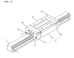
- FIG. 1 is a perspective view illustrating a lubricant supply apparatus according to an embodiment of the present invention, which is used in a linear guide system.
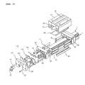
- FIG. 2 is an exploded perspective view of FIG. 1.
- the linear guide system comprises: a guide rail 1, with a plurality of bearing rolling grooves 11 longitudinally formed along opposite side surfaces of the guide rail 1; a slider 2, which is movably fitted over the guide rail 1, with a plurality of balls interposed between the guide rail 1 and the slider 2 and functioning as bearings, and is provided with an endless ball circulation path therein; and a lubricant supply apparatus 140, which is mounted to each of the front and rear ends of the slider 2 and supplies lubricant on the surface of the guide rail 1 while the slider 2 moves along the guide rail 1.
- the slider 2 comprises: a saddle-type block body 10, which is provided with both a machine mounting surface 21 for mounting a machine, such as a table, to the slider 2 and a plurality of unloaded ball paths 22 for circulating the balls; and an end plate 30 mounted to each of the front and rear ends of the block body 10.
- Each of the end plates 30, which are mounted to the front and rear ends of the block body 10, is provided with a ball direction changing path (not shown) to pass the balls from the bearing rolling grooves 11 of the guide rail 1 to the unloaded ball paths 22 of the block body 1.
- the end plates 30 are mounted to the block body 10 using a plurality of locking bolts 35, so that the endless ball circulation path is defined in the slider 2 by the ball direction changing path and the unloaded ball paths 22.
- the linear guide system preferably further comprises: a pipe 70, which is inserted into each of the unloaded ball paths 22; a ball circulation member 50; and a support plate 71, which connects the pipes 70 to the ball circulation member 50 and supports the pipes 70 and the ball circulation member 50.
- each of the end plates 30 is provided with an oil supply hole 36 to supply lubricant to the endless ball circulation path.
- An oil supply nipple 27 is mounted to the oil supply hole 36 such that the nipple 27 is exposed outside the lubricant supply apparatus 140.
- the slider 2 is provided with an upper ball retainer 20 and a lower ball retainer 40 to support the balls in the upper and lower parts of the slider 2.
- an upper ball retainer 20 and a lower ball retainer 40 to support the balls in the upper and lower parts of the slider 2.
- a description of the upper and lower ball retainers reference may be made to Korean Registered Patent No. 496893 .
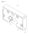
- the lubricant supply apparatus 140 comprises: a first lubricant application unit 143; a second lubricant application unit 145; a partition plate 147, which isolates the first lubricant application unit 143 from the second lubricant application unit 145; and a casing 141, which is mounted to each of the front and rear ends of the slider 2 and receives the first lubricant application unit 143, the second lubricant application unit 145 and the partition plate 147 in a storage chamber 142 thereof.
- the first lubricant application unit 143 is provided with a fitting recess, at which the first lubricant application unit 143 is movably fitted over the guide rail 1, and which is provided with a plurality of contact surfaces 143a to be in contact with respective bearing rolling grooves 11 of the guide rail 1.
- the second lubricant application unit 145 is provided with a fitting recess, at which the second lubricant application unit 145 is movably fitted over the guide rail 1, and which is provided with one upper contact surface 145a and two side contact surfaces 145b which are in contact with the surface of the guide rail 1.
- each of the first lubricant application unit 143 and the second lubricant application unit 145 is required to evenly apply lubricant onto the guide rail 1, so that the first lubricant application unit 143 and the second lubricant application unit 145 is preferably made of a material that easily transfers the lubricant using a capillary phenomenon, for example, a tangled body of fibers, such as felt, having low porosity.
- the casing 141 is mounted to the end plate 30 using locking bolts 25.
- the casing 141 is configured as a plastic body impregnated with lubricant.
- the casing 141 is also provided with a fitting recess, at which the casing 141 is movably fitted over the guide rail 1.
- the fitting recess of the casing 141 is preferably provided with one upper contact surface 142a and/or two side contact surfaces 142b which are in contact with the surface of the guide rail 1.
- the casing 141 has a sealed and anti-vibration structure, which receives the first lubricant application unit 143, the second lubricant application unit 145 and the partition plate 147 in the storage chamber 142 thereof, so that the casing 141 can minimize the leakage of lubricant from its interior to the atmosphere and prevent the introduction of foreign substances into the slider 2 while providing a compact appearance to the slider 2 having the lubricant supply apparatus 140 and enabling the highly precise motion of parts, and executing reliable lubrication for a lengthy period of time.
- the upper contact surface 142a and the side contact surfaces 142b function as sealing surfaces for sealing the surface of the guide rail 1, and are configured as strip-type flanges, which form part of walls of the storage chamber 142, so that the upper and side contact surfaces 142a and 142b determine the locations of the first lubricant application unit 143, the second lubricant application unit 145 and the partition plate 147, and support them in the storage chamber 142.
- the partition plate 147 is preferably made of a plastic material, so that the first lubricant application unit 143 and the second lubricant application unit 145 can be maintained in their parallel states without being tangled, regardless of frictional contact with the guide rail 1, thus evenly applying lubricant onto the surface of the guide rail 1.
- the partition plate 147 is preferably and integrally provided with a plurality of bushings 146, each having two anti-deformation protrusions 146a and 146b.
- the locking bolts 25 are inserted into the respective bushings 146.
- the first anti-deformation protrusion 146a which is provided on the first end of each of the bushings 146, is supported in the casing 141
- the second anti-deformation protrusion 146b which is provided on the second end of each of the bushings 146, is supported in the end plate 30. Due to the first and second anti-deformation protrusions 146a and 146b of the bushings 146, the casing 141 is prevented from being deformed even when it is compressed. Further, the first and second anti-deformation protrusions 146a and 146b of the bushings 146 can prevent deformation of both the first lubricant application unit 143 and the second lubricant application unit 145.
- the above-mentioned lubricant supply apparatus 140 will be assembled as follows. As shown in FIG. 7, first, a sufficient amount of lubricant is impregnated in both the first lubricant application unit 143 and the second lubricant application unit 145. Thereafter, the first lubricant application unit 143, the partition plate 147 and the second lubricant application unit 145 are sequentially assembled in the storage chamber 142 of the casing 141. Thereafter, the lubricant supply apparatus 140 is mounted to each of the front and rear ends of the slider 2 using the locking bolts 25, which are inserted into the respective bushings 146.
- the new lubricant may be supplied both to the first lubricant application unit 143 and to the second lubricant application unit 145 through an air hole 58 in the casing 141.
- the lubricant supply apparatus provides the following advantages.
- the lubricant supply apparatus comprises a first lubricant application unit, which lubricates the guide rail of a linear guide system while being in contact with a plurality of bearing rolling grooves longitudinally formed along opposite side surfaces of the guide rail, and the second lubricant application unit, which lubricates the guide rail while being in contact with both the upper surface and the opposite side surfaces of the guide rail.
- the lubricant supply apparatus can reliably supply a constant amount of lubricant both to the bearings and to the surface of the guide rail, thereby greatly extending the maintenance period of the linear guide system and enabling highly precise linear movement of the linear guide system for a lengthy period of time.
- the casing of the lubricant supply apparatus is configured as a plastic body impregnated with lubricant, and is in contact with the upper surface and/or the opposite side surfaces of the guide rail, so that the casing has a sealed and vibration-resistant structure.
- the lubricant supply apparatus prevents the introduction of foreign substances into the slider, and minimizes the leakage of lubricant from its interior to the atmosphere while providing a compact appearance to the slider having the lubricant supply apparatus and realizing the highly precise motion of parts, and executing reliable lubrication for a lengthy period of time.
- the partition plate is integrally provided with a plurality of bushings, each having an anti-deformation protrusion to prevent deformation of the casing during a process of mounting the casing to the slider.
- the present invention does not require an additional process of assembling separate bushings with the lubricant supply apparatus.
Landscapes
- Engineering & Computer Science (AREA)
- General Engineering & Computer Science (AREA)
- Mechanical Engineering (AREA)
- Bearings For Parts Moving Linearly (AREA)
- Blow-Moulding Or Thermoforming Of Plastics Or The Like (AREA)
- Feeding, Discharge, Calcimining, Fusing, And Gas-Generation Devices (AREA)
- Formation And Processing Of Food Products (AREA)
- Rolling Contact Bearings (AREA)
Applications Claiming Priority (1)
| Application Number | Priority Date | Filing Date | Title |
|---|---|---|---|
| KR1020060028044A KR100743985B1 (ko) | 2006-03-28 | 2006-03-28 | 윤활유 공급장치 |
Publications (3)
| Publication Number | Publication Date |
|---|---|
| EP1840396A2 true EP1840396A2 (de) | 2007-10-03 |
| EP1840396A3 EP1840396A3 (de) | 2008-09-24 |
| EP1840396B1 EP1840396B1 (de) | 2010-08-18 |
Family
ID=38069145
Family Applications (1)
| Application Number | Title | Priority Date | Filing Date |
|---|---|---|---|
| EP07006184A Active EP1840396B1 (de) | 2006-03-28 | 2007-03-26 | Schmiermittelzufuhrvorrichtung |
Country Status (6)
| Country | Link |
|---|---|
| EP (1) | EP1840396B1 (de) |
| JP (1) | JP2007263366A (de) |
| KR (1) | KR100743985B1 (de) |
| AT (1) | ATE478268T1 (de) |
| DE (1) | DE602007008493D1 (de) |
| TW (1) | TW200745454A (de) |
Cited By (4)
| Publication number | Priority date | Publication date | Assignee | Title |
|---|---|---|---|---|
| US8167492B2 (en) * | 2007-03-23 | 2012-05-01 | Schaeffler Technologies AG & Co. KG | Lubricating device for a linear rolling bearing |
| CN103161824A (zh) * | 2011-12-09 | 2013-06-19 | 苏州工业园区高登威科技有限公司 | 滑轨组件 |
| CN103644201A (zh) * | 2013-10-15 | 2014-03-19 | 青岛祥银传动设备有限公司 | 直线导轨滑块用上防尘及直线导轨滑块 |
| US20190203766A1 (en) * | 2016-09-05 | 2019-07-04 | Nsk Ltd. | Linear guide |
Families Citing this family (1)
| Publication number | Priority date | Publication date | Assignee | Title |
|---|---|---|---|---|
| KR101954921B1 (ko) * | 2016-12-05 | 2019-03-07 | (주)원에스티 | 리니어 모션 가이드 및 조립 방법 |
Family Cites Families (7)
| Publication number | Priority date | Publication date | Assignee | Title |
|---|---|---|---|---|
| JP3508503B2 (ja) * | 1997-10-02 | 2004-03-22 | 日本精工株式会社 | リニアガイド装置 |
| US6401867B1 (en) * | 1998-04-16 | 2002-06-11 | Thk Co., Ltd. | Lubricant supply system |
| JP3308944B2 (ja) * | 1998-12-04 | 2002-07-29 | テイエチケー株式会社 | 案内装置の防塵構造 |
| JP4274744B2 (ja) * | 2002-05-31 | 2009-06-10 | Thk株式会社 | 潤滑油供給装置及びこれを用いた直線案内装置 |
| JP4332408B2 (ja) * | 2003-05-29 | 2009-09-16 | 東北リズム株式会社 | 直動転がり案内装置 |
| JP2006046529A (ja) * | 2004-08-05 | 2006-02-16 | Nsk Ltd | 直動案内軸受装置 |
| US7387441B2 (en) * | 2004-08-05 | 2008-06-17 | Nsk Ltd. | Linear guide bearing apparatus |
-
2006
- 2006-03-28 KR KR1020060028044A patent/KR100743985B1/ko not_active Expired - Lifetime
-
2007
- 2007-03-19 TW TW096109365A patent/TW200745454A/zh unknown
- 2007-03-19 JP JP2007070543A patent/JP2007263366A/ja active Pending
- 2007-03-26 EP EP07006184A patent/EP1840396B1/de active Active
- 2007-03-26 AT AT07006184T patent/ATE478268T1/de not_active IP Right Cessation
- 2007-03-26 DE DE602007008493T patent/DE602007008493D1/de active Active
Cited By (6)
| Publication number | Priority date | Publication date | Assignee | Title |
|---|---|---|---|---|
| US8167492B2 (en) * | 2007-03-23 | 2012-05-01 | Schaeffler Technologies AG & Co. KG | Lubricating device for a linear rolling bearing |
| CN103161824A (zh) * | 2011-12-09 | 2013-06-19 | 苏州工业园区高登威科技有限公司 | 滑轨组件 |
| CN103644201A (zh) * | 2013-10-15 | 2014-03-19 | 青岛祥银传动设备有限公司 | 直线导轨滑块用上防尘及直线导轨滑块 |
| CN103644201B (zh) * | 2013-10-15 | 2016-03-16 | 青岛祥银传动设备有限公司 | 直线导轨滑块用上防尘及直线导轨滑块 |
| US20190203766A1 (en) * | 2016-09-05 | 2019-07-04 | Nsk Ltd. | Linear guide |
| US10774872B2 (en) * | 2016-09-05 | 2020-09-15 | Nsk Ltd. | Linear guide |
Also Published As
| Publication number | Publication date |
|---|---|
| EP1840396A3 (de) | 2008-09-24 |
| KR100743985B1 (ko) | 2007-07-30 |
| EP1840396B1 (de) | 2010-08-18 |
| TW200745454A (en) | 2007-12-16 |
| JP2007263366A (ja) | 2007-10-11 |
| DE602007008493D1 (de) | 2010-09-30 |
| ATE478268T1 (de) | 2010-09-15 |
Similar Documents
| Publication | Publication Date | Title |
|---|---|---|
| US8251586B2 (en) | Lubricating member for linear motion rolling guide unit and slider for linear motion rolling guide unit | |
| EP1005953B1 (de) | Staubschutzvorrichtung von Führungseinheit | |
| JP4685723B2 (ja) | 直動案内ユニット | |
| EP1840396B1 (de) | Schmiermittelzufuhrvorrichtung | |
| JPS59190513A (ja) | 往復台用案内装置 | |
| US8070360B2 (en) | Motion guide device and method of lubricating the same | |
| US20090304312A1 (en) | Motion guide device and attachment for motion guide device | |
| US6672765B2 (en) | Direct drive bearing mechanism | |
| US7909512B2 (en) | Lubricating member for linear motion rolling guide unit and slider for linear motion rolling guide unit using the lubricating member | |
| KR102796004B1 (ko) | 운동 안내 장치 및 운동 안내 장치에서 사용되는 윤활 경로 구성요소 | |
| JP2006105310A (ja) | 直動案内ユニット | |
| JP4274744B2 (ja) | 潤滑油供給装置及びこれを用いた直線案内装置 | |
| TWI814296B (zh) | 線性導件 | |
| JPH11280763A (ja) | 直線運動軸受の無給油潤滑構造 | |
| KR100496892B1 (ko) | 슬라이더 및 이 슬라이더가 채택된 직선 미끄럼 볼 베어링 | |
| WO2011024536A1 (ja) | 潤滑油供給装置及びこれを用いた運動案内装置 | |
| JP5377847B2 (ja) | 運動装置 | |
| KR100496893B1 (ko) | 슬라이더 및 이 슬라이더가 채택된 직선 미끄럼 볼 베어링 | |
| CN102612607B (zh) | 线性引导装置 | |
| CN111237336B (zh) | 长期供油的直线导轨副 | |
| JP4233153B2 (ja) | 潤滑油供給装置及びこれを用いた直線運動装置 | |
| JPH11294453A (ja) | 直線運動装置の防塵部材及び直線運動装置 | |
| CN119308939B (zh) | 一种基于柔性弹性元件的液体静压导轨 |
Legal Events
| Date | Code | Title | Description |
|---|---|---|---|
| PUAI | Public reference made under article 153(3) epc to a published international application that has entered the european phase |
Free format text: ORIGINAL CODE: 0009012 |
|
| AK | Designated contracting states |
Kind code of ref document: A2 Designated state(s): AT BE BG CH CY CZ DE DK EE ES FI FR GB GR HU IE IS IT LI LT LU LV MC MT NL PL PT RO SE SI SK TR |
|
| AX | Request for extension of the european patent |
Extension state: AL BA HR MK YU |
|
| PUAL | Search report despatched |
Free format text: ORIGINAL CODE: 0009013 |
|
| AK | Designated contracting states |
Kind code of ref document: A3 Designated state(s): AT BE BG CH CY CZ DE DK EE ES FI FR GB GR HU IE IS IT LI LT LU LV MC MT NL PL PT RO SE SI SK TR |
|
| AX | Request for extension of the european patent |
Extension state: AL BA HR MK RS |
|
| 17P | Request for examination filed |
Effective date: 20090313 |
|
| 17Q | First examination report despatched |
Effective date: 20090414 |
|
| AKX | Designation fees paid |
Designated state(s): AT BE BG CH CY CZ DE DK EE ES FI FR GB GR HU IE IS IT LI LT LU LV MC MT NL PL PT RO SE SI SK TR |
|
| GRAP | Despatch of communication of intention to grant a patent |
Free format text: ORIGINAL CODE: EPIDOSNIGR1 |
|
| GRAS | Grant fee paid |
Free format text: ORIGINAL CODE: EPIDOSNIGR3 |
|
| GRAA | (expected) grant |
Free format text: ORIGINAL CODE: 0009210 |
|
| AK | Designated contracting states |
Kind code of ref document: B1 Designated state(s): AT BE BG CH CY CZ DE DK EE ES FI FR GB GR HU IE IS IT LI LT LU LV MC MT NL PL PT RO SE SI SK TR |
|
| REG | Reference to a national code |
Ref country code: GB Ref legal event code: FG4D |
|
| REG | Reference to a national code |
Ref country code: CH Ref legal event code: EP |
|
| REG | Reference to a national code |
Ref country code: IE Ref legal event code: FG4D |
|
| REF | Corresponds to: |
Ref document number: 602007008493 Country of ref document: DE Date of ref document: 20100930 Kind code of ref document: P |
|
| REG | Reference to a national code |
Ref country code: NL Ref legal event code: VDEP Effective date: 20100818 |
|
| LTIE | Lt: invalidation of european patent or patent extension |
Effective date: 20100818 |
|
| PG25 | Lapsed in a contracting state [announced via postgrant information from national office to epo] |
Ref country code: FI Free format text: LAPSE BECAUSE OF FAILURE TO SUBMIT A TRANSLATION OF THE DESCRIPTION OR TO PAY THE FEE WITHIN THE PRESCRIBED TIME-LIMIT Effective date: 20100818 Ref country code: AT Free format text: LAPSE BECAUSE OF FAILURE TO SUBMIT A TRANSLATION OF THE DESCRIPTION OR TO PAY THE FEE WITHIN THE PRESCRIBED TIME-LIMIT Effective date: 20100818 Ref country code: LT Free format text: LAPSE BECAUSE OF FAILURE TO SUBMIT A TRANSLATION OF THE DESCRIPTION OR TO PAY THE FEE WITHIN THE PRESCRIBED TIME-LIMIT Effective date: 20100818 |
|
| PG25 | Lapsed in a contracting state [announced via postgrant information from national office to epo] |
Ref country code: PL Free format text: LAPSE BECAUSE OF FAILURE TO SUBMIT A TRANSLATION OF THE DESCRIPTION OR TO PAY THE FEE WITHIN THE PRESCRIBED TIME-LIMIT Effective date: 20100818 Ref country code: PT Free format text: LAPSE BECAUSE OF FAILURE TO SUBMIT A TRANSLATION OF THE DESCRIPTION OR TO PAY THE FEE WITHIN THE PRESCRIBED TIME-LIMIT Effective date: 20101220 Ref country code: SI Free format text: LAPSE BECAUSE OF FAILURE TO SUBMIT A TRANSLATION OF THE DESCRIPTION OR TO PAY THE FEE WITHIN THE PRESCRIBED TIME-LIMIT Effective date: 20100818 Ref country code: IS Free format text: LAPSE BECAUSE OF FAILURE TO SUBMIT A TRANSLATION OF THE DESCRIPTION OR TO PAY THE FEE WITHIN THE PRESCRIBED TIME-LIMIT Effective date: 20101218 Ref country code: BG Free format text: LAPSE BECAUSE OF FAILURE TO SUBMIT A TRANSLATION OF THE DESCRIPTION OR TO PAY THE FEE WITHIN THE PRESCRIBED TIME-LIMIT Effective date: 20101118 Ref country code: CY Free format text: LAPSE BECAUSE OF FAILURE TO SUBMIT A TRANSLATION OF THE DESCRIPTION OR TO PAY THE FEE WITHIN THE PRESCRIBED TIME-LIMIT Effective date: 20100818 |
|
| PG25 | Lapsed in a contracting state [announced via postgrant information from national office to epo] |
Ref country code: LV Free format text: LAPSE BECAUSE OF FAILURE TO SUBMIT A TRANSLATION OF THE DESCRIPTION OR TO PAY THE FEE WITHIN THE PRESCRIBED TIME-LIMIT Effective date: 20100818 Ref country code: BE Free format text: LAPSE BECAUSE OF FAILURE TO SUBMIT A TRANSLATION OF THE DESCRIPTION OR TO PAY THE FEE WITHIN THE PRESCRIBED TIME-LIMIT Effective date: 20100818 Ref country code: SE Free format text: LAPSE BECAUSE OF FAILURE TO SUBMIT A TRANSLATION OF THE DESCRIPTION OR TO PAY THE FEE WITHIN THE PRESCRIBED TIME-LIMIT Effective date: 20100818 Ref country code: NL Free format text: LAPSE BECAUSE OF FAILURE TO SUBMIT A TRANSLATION OF THE DESCRIPTION OR TO PAY THE FEE WITHIN THE PRESCRIBED TIME-LIMIT Effective date: 20100818 Ref country code: GR Free format text: LAPSE BECAUSE OF FAILURE TO SUBMIT A TRANSLATION OF THE DESCRIPTION OR TO PAY THE FEE WITHIN THE PRESCRIBED TIME-LIMIT Effective date: 20101119 |
|
| PG25 | Lapsed in a contracting state [announced via postgrant information from national office to epo] |
Ref country code: DK Free format text: LAPSE BECAUSE OF FAILURE TO SUBMIT A TRANSLATION OF THE DESCRIPTION OR TO PAY THE FEE WITHIN THE PRESCRIBED TIME-LIMIT Effective date: 20100818 |
|
| PG25 | Lapsed in a contracting state [announced via postgrant information from national office to epo] |
Ref country code: IT Free format text: LAPSE BECAUSE OF FAILURE TO SUBMIT A TRANSLATION OF THE DESCRIPTION OR TO PAY THE FEE WITHIN THE PRESCRIBED TIME-LIMIT Effective date: 20100818 Ref country code: SK Free format text: LAPSE BECAUSE OF FAILURE TO SUBMIT A TRANSLATION OF THE DESCRIPTION OR TO PAY THE FEE WITHIN THE PRESCRIBED TIME-LIMIT Effective date: 20100818 Ref country code: CZ Free format text: LAPSE BECAUSE OF FAILURE TO SUBMIT A TRANSLATION OF THE DESCRIPTION OR TO PAY THE FEE WITHIN THE PRESCRIBED TIME-LIMIT Effective date: 20100818 Ref country code: RO Free format text: LAPSE BECAUSE OF FAILURE TO SUBMIT A TRANSLATION OF THE DESCRIPTION OR TO PAY THE FEE WITHIN THE PRESCRIBED TIME-LIMIT Effective date: 20100818 Ref country code: EE Free format text: LAPSE BECAUSE OF FAILURE TO SUBMIT A TRANSLATION OF THE DESCRIPTION OR TO PAY THE FEE WITHIN THE PRESCRIBED TIME-LIMIT Effective date: 20100818 |
|
| PLBE | No opposition filed within time limit |
Free format text: ORIGINAL CODE: 0009261 |
|
| STAA | Information on the status of an ep patent application or granted ep patent |
Free format text: STATUS: NO OPPOSITION FILED WITHIN TIME LIMIT |
|
| PG25 | Lapsed in a contracting state [announced via postgrant information from national office to epo] |
Ref country code: ES Free format text: LAPSE BECAUSE OF FAILURE TO SUBMIT A TRANSLATION OF THE DESCRIPTION OR TO PAY THE FEE WITHIN THE PRESCRIBED TIME-LIMIT Effective date: 20101129 |
|
| 26N | No opposition filed |
Effective date: 20110519 |
|
| REG | Reference to a national code |
Ref country code: DE Ref legal event code: R097 Ref document number: 602007008493 Country of ref document: DE Effective date: 20110519 |
|
| PG25 | Lapsed in a contracting state [announced via postgrant information from national office to epo] |
Ref country code: MC Free format text: LAPSE BECAUSE OF NON-PAYMENT OF DUE FEES Effective date: 20110331 |
|
| REG | Reference to a national code |
Ref country code: CH Ref legal event code: PL |
|
| GBPC | Gb: european patent ceased through non-payment of renewal fee |
Effective date: 20110326 |
|
| REG | Reference to a national code |
Ref country code: FR Ref legal event code: ST Effective date: 20111130 |
|
| PG25 | Lapsed in a contracting state [announced via postgrant information from national office to epo] |
Ref country code: MT Free format text: LAPSE BECAUSE OF FAILURE TO SUBMIT A TRANSLATION OF THE DESCRIPTION OR TO PAY THE FEE WITHIN THE PRESCRIBED TIME-LIMIT Effective date: 20100818 |
|
| REG | Reference to a national code |
Ref country code: IE Ref legal event code: MM4A |
|
| PG25 | Lapsed in a contracting state [announced via postgrant information from national office to epo] |
Ref country code: IE Free format text: LAPSE BECAUSE OF NON-PAYMENT OF DUE FEES Effective date: 20110326 Ref country code: FR Free format text: LAPSE BECAUSE OF NON-PAYMENT OF DUE FEES Effective date: 20110331 Ref country code: LI Free format text: LAPSE BECAUSE OF NON-PAYMENT OF DUE FEES Effective date: 20110331 Ref country code: CH Free format text: LAPSE BECAUSE OF NON-PAYMENT OF DUE FEES Effective date: 20110331 |
|
| PG25 | Lapsed in a contracting state [announced via postgrant information from national office to epo] |
Ref country code: GB Free format text: LAPSE BECAUSE OF NON-PAYMENT OF DUE FEES Effective date: 20110326 |
|
| PG25 | Lapsed in a contracting state [announced via postgrant information from national office to epo] |
Ref country code: LU Free format text: LAPSE BECAUSE OF NON-PAYMENT OF DUE FEES Effective date: 20110326 |
|
| PG25 | Lapsed in a contracting state [announced via postgrant information from national office to epo] |
Ref country code: TR Free format text: LAPSE BECAUSE OF FAILURE TO SUBMIT A TRANSLATION OF THE DESCRIPTION OR TO PAY THE FEE WITHIN THE PRESCRIBED TIME-LIMIT Effective date: 20100818 |
|
| PG25 | Lapsed in a contracting state [announced via postgrant information from national office to epo] |
Ref country code: HU Free format text: LAPSE BECAUSE OF FAILURE TO SUBMIT A TRANSLATION OF THE DESCRIPTION OR TO PAY THE FEE WITHIN THE PRESCRIBED TIME-LIMIT Effective date: 20100818 |
|
| PGFP | Annual fee paid to national office [announced via postgrant information from national office to epo] |
Ref country code: DE Payment date: 20250317 Year of fee payment: 19 |