EP1840403B1 - Motorrad-Bremsscheibe - Google Patents
Motorrad-Bremsscheibe Download PDFInfo
- Publication number
- EP1840403B1 EP1840403B1 EP07102002A EP07102002A EP1840403B1 EP 1840403 B1 EP1840403 B1 EP 1840403B1 EP 07102002 A EP07102002 A EP 07102002A EP 07102002 A EP07102002 A EP 07102002A EP 1840403 B1 EP1840403 B1 EP 1840403B1
- Authority
- EP
- European Patent Office
- Prior art keywords
- brake disc
- segment
- segments
- disc according
- segmented
- Prior art date
- Legal status (The legal status is an assumption and is not a legal conclusion. Google has not performed a legal analysis and makes no representation as to the accuracy of the status listed.)
- Not-in-force
Links
- 238000013461 design Methods 0.000 claims description 8
- 239000000463 material Substances 0.000 description 5
- 238000013459 approach Methods 0.000 description 4
- 238000000034 method Methods 0.000 description 3
- 230000008569 process Effects 0.000 description 3
- 230000005540 biological transmission Effects 0.000 description 2
- 230000008859 change Effects 0.000 description 2
- 238000010276 construction Methods 0.000 description 2
- 230000000694 effects Effects 0.000 description 2
- 230000002427 irreversible effect Effects 0.000 description 2
- 230000007774 longterm Effects 0.000 description 2
- 238000012546 transfer Methods 0.000 description 2
- OKTJSMMVPCPJKN-UHFFFAOYSA-N Carbon Chemical compound [C] OKTJSMMVPCPJKN-UHFFFAOYSA-N 0.000 description 1
- 229910001208 Crucible steel Inorganic materials 0.000 description 1
- 229910000831 Steel Inorganic materials 0.000 description 1
- 208000034699 Vitreous floaters Diseases 0.000 description 1
- 230000001133 acceleration Effects 0.000 description 1
- 230000009471 action Effects 0.000 description 1
- 239000004760 aramid Substances 0.000 description 1
- 229920006231 aramid fiber Polymers 0.000 description 1
- 230000015572 biosynthetic process Effects 0.000 description 1
- 229910052799 carbon Inorganic materials 0.000 description 1
- 238000006243 chemical reaction Methods 0.000 description 1
- 239000002131 composite material Substances 0.000 description 1
- 238000006073 displacement reaction Methods 0.000 description 1
- 230000000670 limiting effect Effects 0.000 description 1
- 230000005923 long-lasting effect Effects 0.000 description 1
- 230000007246 mechanism Effects 0.000 description 1
- 239000002184 metal Substances 0.000 description 1
- 230000036961 partial effect Effects 0.000 description 1
- 230000002829 reductive effect Effects 0.000 description 1
- 230000003252 repetitive effect Effects 0.000 description 1
- 230000000717 retained effect Effects 0.000 description 1
- 239000010959 steel Substances 0.000 description 1
- 238000012549 training Methods 0.000 description 1
Images


Classifications
-
- F—MECHANICAL ENGINEERING; LIGHTING; HEATING; WEAPONS; BLASTING
- F16—ENGINEERING ELEMENTS AND UNITS; GENERAL MEASURES FOR PRODUCING AND MAINTAINING EFFECTIVE FUNCTIONING OF MACHINES OR INSTALLATIONS; THERMAL INSULATION IN GENERAL
- F16D—COUPLINGS FOR TRANSMITTING ROTATION; CLUTCHES; BRAKES
- F16D65/00—Parts or details
- F16D65/02—Braking members; Mounting thereof
- F16D65/12—Discs; Drums for disc brakes
- F16D65/121—Discs; Drums for disc brakes consisting of at least three circumferentially arranged segments
-
- F—MECHANICAL ENGINEERING; LIGHTING; HEATING; WEAPONS; BLASTING
- F16—ENGINEERING ELEMENTS AND UNITS; GENERAL MEASURES FOR PRODUCING AND MAINTAINING EFFECTIVE FUNCTIONING OF MACHINES OR INSTALLATIONS; THERMAL INSULATION IN GENERAL
- F16D—COUPLINGS FOR TRANSMITTING ROTATION; CLUTCHES; BRAKES
- F16D65/00—Parts or details
- F16D65/02—Braking members; Mounting thereof
- F16D2065/026—Braking members; Mounting thereof characterised by a particular outline shape of the braking member, e.g. footprint of friction lining
-
- F—MECHANICAL ENGINEERING; LIGHTING; HEATING; WEAPONS; BLASTING
- F16—ENGINEERING ELEMENTS AND UNITS; GENERAL MEASURES FOR PRODUCING AND MAINTAINING EFFECTIVE FUNCTIONING OF MACHINES OR INSTALLATIONS; THERMAL INSULATION IN GENERAL
- F16D—COUPLINGS FOR TRANSMITTING ROTATION; CLUTCHES; BRAKES
- F16D65/00—Parts or details
- F16D65/02—Braking members; Mounting thereof
- F16D2065/13—Parts or details of discs or drums
- F16D2065/1304—Structure
- F16D2065/1312—Structure circumferentially segmented
-
- F—MECHANICAL ENGINEERING; LIGHTING; HEATING; WEAPONS; BLASTING
- F16—ENGINEERING ELEMENTS AND UNITS; GENERAL MEASURES FOR PRODUCING AND MAINTAINING EFFECTIVE FUNCTIONING OF MACHINES OR INSTALLATIONS; THERMAL INSULATION IN GENERAL
- F16D—COUPLINGS FOR TRANSMITTING ROTATION; CLUTCHES; BRAKES
- F16D65/00—Parts or details
- F16D65/02—Braking members; Mounting thereof
- F16D2065/13—Parts or details of discs or drums
- F16D2065/134—Connection
- F16D2065/1356—Connection interlocking
-
- F—MECHANICAL ENGINEERING; LIGHTING; HEATING; WEAPONS; BLASTING
- F16—ENGINEERING ELEMENTS AND UNITS; GENERAL MEASURES FOR PRODUCING AND MAINTAINING EFFECTIVE FUNCTIONING OF MACHINES OR INSTALLATIONS; THERMAL INSULATION IN GENERAL
- F16D—COUPLINGS FOR TRANSMITTING ROTATION; CLUTCHES; BRAKES
- F16D65/00—Parts or details
- F16D65/02—Braking members; Mounting thereof
- F16D2065/13—Parts or details of discs or drums
- F16D2065/134—Connection
- F16D2065/1376—Connection inner circumference
-
- F—MECHANICAL ENGINEERING; LIGHTING; HEATING; WEAPONS; BLASTING
- F16—ENGINEERING ELEMENTS AND UNITS; GENERAL MEASURES FOR PRODUCING AND MAINTAINING EFFECTIVE FUNCTIONING OF MACHINES OR INSTALLATIONS; THERMAL INSULATION IN GENERAL
- F16D—COUPLINGS FOR TRANSMITTING ROTATION; CLUTCHES; BRAKES
- F16D65/00—Parts or details
- F16D65/02—Braking members; Mounting thereof
- F16D2065/13—Parts or details of discs or drums
- F16D2065/134—Connection
- F16D2065/1392—Connection elements
Definitions
- the invention relates to a segmented brake disk according to the preamble of patent claim 1.
- segment brake disc is from the US-A-3 907 076 known. Similar segment brake discs are off US-A3 895,693 as well as from the not previously published EP 1 696 148 A known.
- the construction is characterized by the fact that the segments are only supported on the carrier disc during brake torque application and do not come into contact with each other. The defined gap between the segments is not closed when brake torque is applied. Due to the two-fold plate attachment occurs at Bremsmomentbeauschlagung to a torque that acts in the direction of rotation in each case rear tab of the segment and the rear seat of the support ring with a pressure torque applied to each front flap of the segment and the front seat of the support ring with a tensile torque , This construction approach leads to long-term stress to a dynamic deformation of the pins of the carrier ring and the holes of the mounting tabs of the ring sections.
- the current state of the art in disc brakes for agricultural vehicles is based on the principle that the friction ring of the brake disc consists of an uninterrupted, radially rotating friction ring on which by hydraulic assistance by a single or multi-piston caliper pads located in the caliper on the axially movable piston be pressed against the friction ring of the brake disc.
- a frictional torque is built up between the brake pad and the brake disc, by means of which a negative acceleration torque (braking torque) is generated via the physical principle of the conversion of kinetic energy into thermal energy.
- the friction ring of the brake disc is either materially connected to the wheel hub receptacle of the inner ring (carrier disc) or connected via rivet-like connecting elements (so-called “floaters”) without play or with play with the inner ring to be fastened to the wheel hub.
- Object of the present invention is to develop the segment brake disc of the type mentioned and to improve the effect that the torques of the disc segments are taken cheaper.
- FIG. 1 shows a segment brake disc with twelve identical segments 20th
- FIG. 2 is one of the segments 20 (see arrow) shown in detail, as shown in FIG. 1 is used.
- FIG. 3 schematically, a brake pad 22 is shown.
- the brake disc direction of rotation is shown by the arrow 24.
- the segment 20 is not mirrored to a mirror plane 26 defined by a wheel axle 38 and a radial extending centrally between two attachment points 28, 30 of the segment 20.
- the rearward in the direction of rotation 24 attachment point 28 of the segment 20 shown is more heavily loaded during braking than the front attachment point 30th
- Each segment has a support surface 32 located at the rear in the brake disk rotation direction 24 at its edge and a corresponding contact surface 34, these surfaces are adapted to one another in terms of shape. In the case of a braking process, they rely on each other. They are preferably curved. Preferably, the contact line 31 does not extend through the wheel axle 38, rather it intersects the mirror plane 26 between the wheel axle 38 and the segment 20, preferably closer to the latter.
- FIG. 3 shows two juxtaposed segments 20. Furthermore, the brake pad 22 is shown.
- the FIGS. 4 to 8 show different means to hold adjacent segments 20 in the same radial plane.
- There are axial-radial connectors 40 are provided with which each segment 20 is held on rivets or screws on the carrier 36.
- Fig. 4 . 6 and 7 is in the left, in the direction of rotation (preferably) forward segment in the contact surface 34 a parallel holding groove 42 is provided, in the right segment is an associated parallel-holding spring.
- the attachment points are held by axial-radial connectors, riveted or screwed. Rivets or screws are shown.
- version 2 the latter is retained, but now a web is provided in each segment, in each of which a holding means in the form of a groove roller 44 engages as AxialHalter.
- FIG. 5 . 8, 9 shows
- the segments have 20 lugs 46 and in the neighboring segment matching recesses. This thermal expansion joints are provided.
- Segmented brake disc for motorized land vehicles consisting of a different number and segments in different shapes with it on the respective direction of rotation in the following segment and this bringing into position segments.
- the segmented brake disc is intended for use with motorized land vehicles, and within this vehicle category it should be subsumed: cars, light trucks (up to 7.5 tons), motorcycles, scooters, quads.
- the segment brake disc is constructed in its design-side configuration so that a segment brings in load application by the brake pads of the caliper (braking torque) each following in the braking direction segment by a lever mechanism in position.
- the individual segments are based here on the one hand on the inner ring and on the other hand on the respectively following segment and bring this by load application via a torque in position.
- the segments are not firmly connected to the support ring via pins in this design approach, but are only on formed within the outer radius of the carrier ring "lugs" on. About this contact surface, the braking torque is transmitted.
- the special shape of the segments on the one hand and the "lugs" of the carrier ring on the other hand prevent a radial direction, favored by centrifugal displacement of the segments.
- An axial offset of the segments is avoided by two opposing connectors which are bolted together. The connectors are only firmly bolted together, not with the segments or the carrier ring. The connectors do not transmit braking torque.
- segments are used in different numbers and shapes
- the braking torque is transmitted from the segments to a larger, dynamically loadable cross-section of the carrier ring.
- the in-position Bring a segment through each preceded in the direction of rotation segment dynamic load peaks on the support ring avoided or significantly reduced.
- the shape of the tabs of the segments and the "lugs" of the carrier ring the braking torque to a transfer larger material cross section. Fatigue and wear is effectively prevented.
- This principle is clearly superior to the design approach of the already registered utility model on the one hand and the rivet-like fasteners used in brake discs of conventional design between friction ring and support ring under long-term stress aspects and associated wear and tear.
- Fig. 1 shows a partial cross section through a segment brake disc according to the invention.
- the segment brake disc consists of a carrier ring 36 and individual segments 20 in different numbers and connectors 40 in the same number.
- the segments are based, on the one hand, on the carrier ring 36 and, on the other hand, on the segment following in the direction of rotation or bring it into position by torque transmission, in particular pivoting it slightly inwards.
- the segments 20 can expand and contract under the influence of force / heat in a controlled manner, without it being possible for the segments 20 and thus the friction ring of the brake disk to become distorted.
- the segments 20 are introduced into the carrier ring 36 in the form that they are not displaced in the radial direction.
- the segments 20 have within the recess of the support ring 36 a defined (floating) game held.
- the segments are secured by means of connectors 42, 44 against axial misalignment and these connectors do not transmit braking torque.
- a loaded by braking torque segment brings each subsequent in the direction of rotation segment by a loading torque in such a position that the torque is transmitted to the inner ring 36 with controlled dynamic load without or with low dynamic load peaks at the contact surface between the segment and support ring 36.
- segments are mounted on an inner ring instead of a rotating, continuous friction ring, which allow a controlled expansion of the material used under force / heat without formation of thermal bridges between the segments.
- the segments are based on force on the one hand on the carrier ring and on the other hand on the next segment in the direction of rotation and bring the next segment by a torque in position.
- the segments are stored with defined play in the carrier ring.
- the segments transmit the braking torque a contact surface on the support ring, either a fixed screw or rivet connection between the segments and the support ring is given, nor are the segments connected via pins to the support ring.
- the segments are held in place by connectors, which in turn do not transfer power. When disassembling the connectors, the segments can be removed axially in both directions from the carrier disk.
Landscapes
- Engineering & Computer Science (AREA)
- General Engineering & Computer Science (AREA)
- Mechanical Engineering (AREA)
- Braking Arrangements (AREA)
Description
- Die Erfindung bezieht sich auf eine Segment-Bremsscheibe nach dem Oberbegriff des Patentanspruchs 1.
- Eine derartige Segment-Bremsscheibe ist aus der
US-A-3 907 076 bekannt. Ähnliche Segment-Bremsscheiben sind ausUS-A3 895 693 sowie aus der nicht vorveröffentlichtenEP 1 696 148 A bekannt. - Aus der
DE 297 13 076 U1 ist eine Segment-Bremsscheibe des gleichen Erfinders vorbekannt, die das Prinzip des unterbrochenen Reibrings erstmals aufgreift. Hier wurde das Prinzip einer kontrollierten Wärmeausdehnung des Reibrings der Segment-Scheibenbremse und die Vermeidung von durch Kraft-/ Wärmeeinwirkung bedingten Gefüge- und Strukturveränderung des Materials durch die Verwendung von einzelnen Segmenten in unterschiedlicher Anzahl anstelle eines ununterbrochenen Reibrings erstmals realisiert. Die einzelnen Ringabschnitte (Segmente) werden über Befestigungslaschen in auf der Trägerscheibe ausgebildete Aufnahmen gehalten und durch Gewindeschrauben in den mit Gewindebohrungen versehenen Aufnahmen (Zapfen) an der Trägerscheibe befestigt. Zwischen den einzelnen Segmenten kann es aufgrund des definierten Spaltmaßes zwischen den Ringabschnitten (Segmenten) nicht mehr zu Wärmebrücken zwischen denselben kommen. Damit wird einem Planverzug des Reibrings vorgebeugt. Die Konstruktion zeichnet sich dadurch aus, dass sich die Segmente bei Bremsmomentbeauschlagung ausschließlich an der Trägerscheibe abstützen und nicht miteinander in Kontakt geraten. Das definierte Spaltmaß zwischen den Segmenten wird bei Bremsmomentbeauschlagung nicht geschlossen. Durch die zweifache Laschenbefestigung kommt es bei Bremsmomentbeauschlagung zu einem Drehmoment, das die in Drehrichtung jeweils hinten liegenden Lasche des Segmentes sowie die hintere Aufnahme des Trägerrings mit einem Druckmoment beaufschlagt, die jeweils vorne liegenden Lasche des Segmentes sowie die vordere Aufnahme des Trägerrings mit einem Zugmoment beaufschlagt. Dieser Konstruktionsansatz führt bei langandauernder Belastung zu einer dynamischen Verformung der Zapfen des Trägerings und der Bohrungen der Befestigungslaschen der Ringabschnitte. - Der gängige Stand der Technik bei Scheibenbremsen für Landkraftfahrzeuge beruht auf dem Prinzip, dass der Reibring der Bremsscheibe aus einem ununterbrochenen, radial umlaufenden Reibring besteht, an welchem per Hydraulikunterstützung durch einen Einzel- oder Mehrkolben-Bremssattel die im Bremssattel befindlichen Beläge über die axial beweglichen Kolben an den Reibring der Bremsscheibe gepresst werden. Über diesen Druck wird ein Reibmoment zwischen Bremsbelag und Bremsscheibe aufgebaut, mittels welchem über das physikalische Prinzip der Umwandlung von Bewegungs- in Wärmeenergie ein negatives Beschleunigungs-Moment (Bremsmoment) erzeugt wird. Der Reibring der Bremsscheibe ist dabei entweder mit der Radnabenaufnahme des Innenrings (Trägerscheibe) materialschlüssig verbunden oder über nietähnliche Verbindungselemente (sogenannte "Floater") spielfrei oder mit Spiel mit dem an der Radnabe zu befestigendem Innenring verbunden.
- Aufgrund des ununterbrochenen Reibrings - der bei gängigen Bremsscheiben entweder aus einem Stahl-Grauguss-Material oder einem geschmiedeten Stahl hergestellt wird; seit wenigen Jahren kommen auch Kohlenstoff-Verbundmaterialien oder Aramidfasern zum Einsatz - entstehen bei diesen nach herkömmlichen Prinzip konstruierten Bremsscheiben während des Bremsvorgangs unterschiedliche Temperaturzonen entlang des Reibrings, da die Bremsbeläge während des Bremsvorgangs nur jeweils einen Bruchteil des Reibrings beaufschlagen. Durch die unterschiedlichen Temperaturzonen kann es zum irreversiblen Planverzug des Reibrings kommen, da sich das Metall (oder ein anderes zur Verwendung kommendes Material) je nach temperaturdynamischem Ausdehnungskoeffizienten nur bis zu einem bestimmten Grad radial und axial reversibel ausdehnen kann. Wird durch eine punktuelle Belastungsspitze mit hoher dynamischer Temperaturänderung oder durch eine langandauernde Belastung der temperaturdynamische Ausdehnungskoeffizient des verwendeten Materials überschritten, kommt es zu einem irreversiblen Planverzug des Reibrings. Je nach Belastungsintensität können hiervon auch Bremsscheiben mit vergleichsweise geringer Laufleistung betroffen sein. Der Planverzug führt zu einer ungleichmäßigen, nicht mehr vollständig planen Bremsscheibe. Eine nicht mehr vollständig plane Bremsscheibe (außerhalb des erlaubten Toleranzmaßes) kann nicht mehr die vollständige Bremsleistung entwickeln.
- Aufgabe der vorliegenden Erfindung ist es, die Segment-Bremsscheibe der eingangs genannten Art weiterzuentwickeln und dahingehend zu verbessern, dass die Drehmomente der Scheibensegmente günstiger aufgenommen werden.
- Diese Aufgabe wird gelöst durch die Merkmale des Patentanspruchs 1.
- Weitere Ausbildungen finden sich in den weiteren Ansprüchen.
- Weitere Vorteile und Merkmale der Erfindung ergeben sich aus den übrigen Ansprüchen sowie der nun folgenden Beschreibung von nicht einschränkend zu verstehenden Ausführungsbeispielen der Erfindung, die im folgenden unter Bezugnahme auf die Zeichnung näher erläutert werden. In dieser Zeichnung zeigen:
- Fig. 1:
- eine Draufsicht auf eine Segment-Bremsscheibe mit zwölf bauglei- chen Segmenten,
- Fig. 2:
- eine Draufsicht auf ein Segment der Bremsscheibe gemäß
Fig. 1 , - Fig. 3:
- eine perspektivische Darstellung zweier Segmente ähnlich
Figur 2 zur Erläuterung der Funktion, - Fig. 4:
- eine perspektivische Darstellung einer zweiten Segment- Brems- scheibe mit zwei abgenommenen Segmenten, einmal in der Version 1 und einmal in der Version 2,
- Fig. 5:
- eine Darstellung eines Kranzes von Segmenten ohne Scheibe, zwei Segmente sind zur besseren Erkennbarkeit der Zeichnung separat dargestellt,
- Fig. 6:
- eine perspektivische Darstellung ähnlich
Figur 4 einer dritten Seg- ment-Bremsscheibe, wiederum sind zwei Segmente zur besseren Verständlichkeit separat dargestellt, - Fig. 7:
- eine Draufsicht auf zwei separat dargestellte Segmente in Version 1 für die Bremsscheibe gemäß
Figur 9 , - Fig. 8:
- eine Draufsicht wie
Figur 7 , jedoch in einer Version 2, für die Seg- ment-Bremsscheibe nachFigur 9 , - Fig. 9:
- eine Draufsicht auf eine vierte Ausführung einer Segment- Bremsscheibe, bei der zwei Segmente entnommen sind,
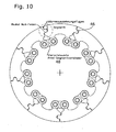
- Fig. 10:
- eine Draufsicht auf eine fünfte Ausführung einer Segment- Bremsscheibe,
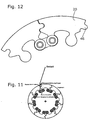
- Fig. 11:
- eine Draufsicht auf zwei nebeneinander angeordnete Segmente als Detail aus
Figur 12 und - Fig. 12:
- eine Draufsicht auf eine sechste Ausführung einer Segment- Bremsscheibe.
-
Figur 1 zeigt eine Segment-Bremsscheibe mit zwölf baugleichen Segmenten 20. - In
Figur 2 ist eines der Segmente 20 (siehe Pfeil) im Einzelnen dargestellt, wie es inFigur 1 verwendet wird. InFigur 3 ist schematisch ein Bremsbelag 22 dargestellt. Die Bremsscheibendrehrichtung ist durch den Pfeil 24 dargestellt. Das Segment 20 ist nicht spiegelbildlich zu einer Spiegelebene 26, die durch eine Radachse 38 und eine Radiale definiert ist, welche mittig zwischen zwei Befestigungspunkten 28, 30 des Segments 20 verläuft. Der in Drehrichtung 24 hinten liegende Befestigungspunkt 28 des gezeigten Segments 20 ist im Bremsvorgang stärker belastet als der vordere Befestigungspunkt 30. - Jedes Segment hat eine in Bremsscheiben-Drehrichtung 24 hinten liegende Abstützfläche 32 an seiner Kante und eine entsprechende Anlagefläche 34, diese Flächen sind formmäßig aneinander angepasst. Im Falle eines Bremsvorgangs stützen sie sich aneinander ab. Sie sind vorzugsweise gekrümmt. Vorzugsweise verläuft die Berührungslinie 31 nicht durch die Radachse 38, vielmehr schneidet sie die Spiegelebene 26 zwischen der Radachse 38 und dem Segment 20, vorzugsweise näher am letzteren.
- sie die Spiegelebene 26 zwischen der Radachse 38 und dem Segment 20, vorzugsweise näher am letzteren.
- Der in Bremsrichtung, also entgegen der Drehrichtung 24, vorn befindliche Befestigungspunkt 28 ist ein gelagerter Drehpunkt. 36 ist der Träger, an dem alle Segmente 20 befestigt sind.
-
Figur 3 zeigt zwei nebeneinander angeordnete Segmente 20. Weiterhin ist der Bremsbelag 22 gezeigt. DieFiguren 4 bis 8 zeigen unterschiedliche Mittel, um benachbarte Segmente 20 in derselben Radialebene zu halten. Es sind Axial-Radial-Verbinder 40 vorgesehen, mit denen jedes Segment 20 über Niete oder Schrauben am Träger 36 gehalten ist. InFig. 4 ,6 und7 ist im linken, in Drehrichtung (vorzugsweise) vorn liegenden Segment in der Anlagefläche 34 eine Parallelhalte-Nut 42 vorgesehen, im rechten Segment ist eine zugehörige Parallelhalte-Feder. Die Befestigungspunkte werden durch Axial-Radial-Verbinder, vernietet oder verschraubt, gehalten. Niete oder Schrauben sind dargestellt. In der Version 2 ist Letzteres beibehalten, nunmehr ist aber in jedem Segment ein Steg vorgesehen, in dem jeweils ein Haltemittel in Form einer Nutrolle 44 als AxialHalter eingreift. Ähnliches zeigt auchFigur 5 ,8, 9 . - Gemäß
Fig. 10 und11 haben die Segmente 20 Nasen 46 und im Nachbarsegment dazu passende Ausnehmungen. Dabei sind Wärmeausdehnungsfugen vorgesehen. - Segment-Bremsscheibe für motorisierte Landkraftfahrzeuge bestehend aus einer unterschiedlichen Anzahl und in unterschiedlicher Formgebung befindlichen Segmenten mit sich an dem in Drehrichtung jeweils folgenden Segment abstützenden und dieses in Position bringenden Segmenten.
- Die Segment-Bremsscheibe ist für motorisierte Landkraftfahrzeuge vorgeshen, innerhalb dieser Fahrzeugkategorie sollen subsumiert sein: PKW, leichte LKW (bis 7,5 to), Motorräder, Motorroller, Quads. Die Segment-Bremsscheibe ist dabei in ihrer konstruktionsseitigen Ausgestaltung so aufgebaut, dass ein Segment bei Lastaufbringung durch die Bremsbeläge des Bremssattels (Bremsmoment) das jeweils in Bremsrichtung folgende Segment durch einen Hebelmechanismus in Position bringt. Die einzelnen Segmente stützen sich hierbei einerseits am Innenkranz und andererseits an dem jeweils folgenden Segment ab und bringen dieses durch Lastaufbringung über ein Drehmoment in Position.
- Es werden zweierlei Ansätze erfüllt: Einerseits der bereits bekannten Überwindung des Planverzuges des Reibrings durch die Verwendung von Segmenten anstelle eines umlaufenden, ununterbrochenen Reibrings. Die Segmente können sich durch definiertes Axial- und Radialspiel bei Kraft-/ Wärmeeinwirkung kontrolliert ausdehnen und wieder zusammenziehen, ohne dass es zu unkontrollierten Wärmebrücken zwischen den Segmenten kommt. Überdies wird durch die Abstützung eines Segmentes am in Drehrichtung jeweils folgenden Segment das jeweils folgende Segment durch eine kontrollierte Hebelwirkung in Position gebracht, so dass bei einer Bremsmomentbeaufschlagung ein geschlossener, nacheinander und sich wiederholender Bewegungsablauf aller Segmente erfolgt. Dadurch, dass das jeweils folgende Segment von dem vorangehenden Segment in Position gebracht wird, erfolgt die Momentübertragung auf den Innenring mit geringeren dynamischen Lastspitzen an der Kontaktfläche zwischen der in Drehrichtung vorne liegenden Lasche des Segmentes und der "Nase" des Trägerrings.
- Die Segmente sind bei diesem Konstruktionsansatz nicht fest mit dem Trägerring über Zapfen verbunden, sondern liegen lediglich an innerhalb des äußeren Radius des Trägerrings ausgebildeten "Nasen" an. Über diese Kontaktfläche wird das Bremsmoment übertragen. Die besondere Formgebung der Segmente einerseits und der "Nasen" des Trägerrings andererseits verhindern einen in radialer Richtung, durch Fliehkraft begünstigten Versatz der Segmente. Ein axialer Versatz der Segmente wird durch zwei einander gegenüberliegende Verbinder vermieden, die miteinander verschraubt sind. Die Verbinder sind nur miteinander fest verschraubt, nicht mit den Segmenten oder dem Trägerring. Die Verbinder übertragen kein Bremsmoment.
- Einerseits werden Segmente in unterschiedlicher Anzahl und Formgebung verwendet, andererseits wird das Bremsmoment von den Segmenten auf einen größeren, dynamisch belastbareren Querschnitt des Trägerings übertragen. Durch die In-Position-Bringung eines Segmentes durch das jeweils in Drehrichtung vorangestellte Segment werden dynamische Lastspitzen auf dem Trägerring vermieden bzw. deutlich reduziert. Darüber hinaus wird durch die Formgebung der Laschen der Segmente und der "Nasen" des Trägerings das Bremsmoment auf einen größeren Materialquerschnitt übertragen. Ermüdungs- und Verschleißerscheinungen wird wirksam vorgebeugt. Dieses Prinzip ist dem Konstruktionsansatz des bereits angemeldeten Gebrauchmusters einerseits und den bei Bremsscheiben herkömmlicher Bauart verwendeten nietähnlichen Verbindungselementen zwischen Reibring und Trägerring unter Langzeitbelastungsaspekten und damit verbundenen Verschleißerscheinungen deutlich überlegen.
-
Fig. 1 zeigt einen teilweisen Querschnitt durch eine erfindungsgemäße Segment-Bremsscheibe. - Die Segment-Bremsscheibe besteht aus einem Trägerring 36 und einzelnen Segmenten 20 in unterschiedlicher Anzahl und Verbindern 40 in gleicher Anzahl. Die Segmente stützen sich einerseits am Trägering 36 und andererseits am in Drehrichtung nachfolgenden Segment ab bzw. dieses durch Momentübertragung in Position bringen, insbesondere etwas nach innen schwenken. Die Segmente 20 können sich unter Kraft-/ Wärmeeinwirkung kontrolliert ausdehnen und wieder zusammenziehen, ohne dass es zu einem Planverzug der Segmente 20 und damit des Reibrings der Bremsscheibe kommen kann. Die Segmente 20 sind in den Trägerring 36 in der Form eingebracht, dass sie in radialer Richtung nicht verschiebbar sind. Die Segmente 20 haben innerhalb der Aussparung des Trägerrings 36 ein definiertes (Floating-) Spiel inne. Die Segmente sind mittels Verbindern 42, 44 gegen axialen Versatz gesichert und diese Verbinder übertragen kein Bremsmoment. Ein durch Bremsmoment belastetes Segment bringt das jeweils in Drehrichtung nachfolgende Segment durch ein Belastungsmoment dergestalt in Position, dass die Momentübertragung auf den Innenring 36 mit kontrollierter dynamischer Last ohne bzw. mit geringen dynamische Lastspitzen an der Kontaktfläche zwischen Segment und Trägerring 36 erfolgt.
- Bei einer Bremsscheibe für Landkraftfahrzeuge sind auf einem Innenring anstelle eines umlaufenden, ununterbrochenen Reibrings Segmente angebracht, die eine kontrollierte Ausdehnung des verwendeten Materials unter Kraft-/ Wärmeeinwirkung ohne Bildung von Wärmebrücken zwischen den Segmenten zulassen. Die Segmente stützen sich bei Krafteinwirkung einerseits am Trägering und andererseits am in Drehrichtung folgenden Segment ab und bringen das jeweils folgende Segment durch ein Drehmoment in Position. Die Segmente sind mit definiertem Spiel im Trägerring gelagert. Die Segmente übertragen das Bremsmoment über eine Kontaktfläche auf den Trägerring, weder ist eine feste Schraub- oder NietVerbindung zwischen den Segmenten und dem Trägerring gegeben, noch sind die Segmente über Zapfen mit dem Trägerring verbunden. Die Segmente werden durch Verbinder in Position gehalten, die ihrerseits keine Kraftübertragung übernehmen. Bei Demontage der Verbinder können die Segmente axial in beide Richtungen aus der Trägerscheibe entnommen werden.
Claims (15)
- Segment-Bremsscheibe einer Scheibenbremse mit Bremsbelag, insbesondere für Motorräder, mit einer Vielzahl von Segmenten, die an einem Träger gehalten sind, wobei die Segmente jeweils in zwei Befestigungspunkten mit dem Träger verbunden sind, wobei jedes Segment (20) eine in Bremsscheiben-Drehrichtung hinten liegende Abstützfläche aufweist, jedes Segment (20) eine in Bremsscheiben-Drehrichtung vorn liegende Anlagefläche aufweist, und Abstützfläche und Anlagefläche in ihrer Form einander angepasst sind, dadurch gekennzeichnet, dass die Segmente in Umfangrichtung kürzer sind als die entsprechende Länge des Bremsbelages (22).
- Segment-Bremsscheibe nach Anspruch 1, dadurch gekennzeichnet, dass im Bremszustand die Abstützfläche eines Segments in Kontakt ist an der Anlagefläche (34) des in Bremsscheiben-Drehrichtung unmittelbar dahinter liegenden Segments (20) und sich an der Anlagefläche (34) abstützt.
- Segment-Bremsscheibe nach Anspruch 1, dadurch gekennzeichnet, dass die Abstützfläche und die Anlagefläche jeweils gekrümmt verlaufen.
- Segment-Bremsscheibe nach Anspruch 1, dadurch gekennzeichnet, dass im Bremszustand die Abstützfläche entlang einer Berührungslinie an der Anlagefläche (34) des in Bremsscheiben-Drehrichtung unmittelbar dahinter liegenden Segments anliegt, und dass die Berührungslinie nicht durch die Radachse verläuft.
- Segment-Bremsscheibe nach Anspruch 4, dadurch gekennzeichnet, dass die Berührungslinie eine Spiegelebene zwischen der Radachse und dem Segment schneidet, wobei die Spiegelebene definiert ist durch die Radachse und eine Radiale, welche mittig zwischen zwei Befestigungspunkten des Segments, mit denen das Segment (20) jeweils an einem Träger (36) befestigt ist, verläuft.
- Segment-Bremsscheibe nach Anspruch 1, dadurch gekennzeichnet, dass die Segmente (20) spiegelbildlich oder nicht spiegelbildlich sind zu einer Spiegelebene (26), die definiert ist durch die Radachse (38) und eine Radiale, welche mittig zwischen den beiden Befestigungspunkten (28, 30) hindurchläuft.
- Segment-Bremsscheibe nach einem der Ansprüche 1 bis 6, dadurch gekennzeichnet, dass einer der beiden Befestigungspunkte (28, 30) ein gelagerter Abstützpunkt (gelagerter Drehpunkt) eines Segments (20) ist und der Abstützfläche näher ist als der Anlagefläche (34).
- Segment-Bremsscheibe nach einem der Ansprüche 1 bis 7, dadurch gekennzeichnet, dass einer der beiden Befestigungspunkte (28, 30) ein gelagerter Abstützpunkt ist und sich etwa auf derselben Radialen befindet wie die Abstützfläche.
- Segment-Bremsscheibe nach einem der Ansprüche 1 bis 8, dadurch gekennzeichnet, dass die beiden Befestigungspunkte (28, 30) unterschiedlich ausgebildet sind, wobei der in der Bremsschreiben-Drehrichtung vorn liegende Abstützpunkt als Widerlager ausgebildet ist, oder dass die beiden Befestigungspunkte (28, 30) baugleich ausgebildet sind.
- Segment-Bremsscheibe nach einem der Ansprüche 1 bis 9, dadurch gekennzeichnet, dass die beiden Befestigungspunkte (28, 30) unterschiedlich ausgebildet sind, wobei der in Bremsschreiben-Drehrichtung hinten liegende Abstützpunkt als gelagerter Drehpunkt ausgebildet ist und höhere Kräfte aufnehmen kann als der andere, oder dass die beiden Befestigungspunkte (28, 30) baugleich ausgebildet sind.
- Segment-Bremsscheibe nach einem der Ansprüche 1 bis 10, dadurch gekennzeichnet, dass zwischen den einzelnen Segmenten (20) Mittel vorgesehen sind, die benachbarte Segmente (20) in der gleichen Radialebene halten, insbesondere eine Parallelhalte-Feder und zugehörige Parallelhalte-Nut (42), Stege in den benachbarten Segmenten (20), in denen Nutrollen (44) als Axialhalter vorgesehen sind und in Umfangsrichtung vorspringende Nasen (46), die in zugehörige Ausnehmungen eingreifen.
- Segment-Bremsscheibe einem der Ansprüche 1 bis 11, dadurch gekennzeichnet, dass in den Befestigungspunkten (28, 30) zwischen den Segmenten (20) und dem Träger (36) Axial-Radialverbinder (40) oder Axial-Segementverbinder (48) vorgesehen sind, und dass sie vorzugsweise vernietet oder verschraubt sind.
- Segment-Bremsscheibe nach Anspruch 12, dadurch gekennzeichnet, dass die Axial-Radialverbinder (40) oder Axial-Segementverbinder (48) jeweils einen Stift oder zwei Stifte aufweisen, und dass vorzugsweise der Stift als Schraube oder Niet ausgebildet ist.
- Segment-Bremsscheibe einem der Ansprüche 1 bis 13, dadurch gekennzeichnet, dass sie mehr als 12, vorzugsweise mehr als 15, insbesondere mehr als 17 einzelne Segmente (20) aufweist.
- Segment-Bremsscheibe einem der Ansprüche 1 bis 14, dadurch gekennzeichnet, dass die einzelnen Segmente (20) baugleich sind.
Applications Claiming Priority (1)
| Application Number | Priority Date | Filing Date | Title |
|---|---|---|---|
| DE102006006217 | 2006-02-09 |
Publications (3)
| Publication Number | Publication Date |
|---|---|
| EP1840403A2 EP1840403A2 (de) | 2007-10-03 |
| EP1840403A3 EP1840403A3 (de) | 2008-10-29 |
| EP1840403B1 true EP1840403B1 (de) | 2010-09-01 |
Family
ID=38000837
Family Applications (1)
| Application Number | Title | Priority Date | Filing Date |
|---|---|---|---|
| EP07102002A Not-in-force EP1840403B1 (de) | 2006-02-09 | 2007-02-08 | Motorrad-Bremsscheibe |
Country Status (4)
| Country | Link |
|---|---|
| EP (1) | EP1840403B1 (de) |
| AT (1) | ATE479853T1 (de) |
| DE (1) | DE502007004896D1 (de) |
| ES (1) | ES2351472T3 (de) |
Families Citing this family (3)
| Publication number | Priority date | Publication date | Assignee | Title |
|---|---|---|---|---|
| JPWO2011049172A1 (ja) * | 2009-10-21 | 2013-03-14 | サンスター技研株式会社 | ノイズ低減ブレーキディスク |
| TWI480475B (zh) * | 2012-10-09 | 2015-04-11 | Ashima Ltd | Brake disc device |
| TWI735402B (zh) * | 2021-02-09 | 2021-08-01 | 許再勝 | 一體式浮動碟 |
Family Cites Families (5)
| Publication number | Priority date | Publication date | Assignee | Title |
|---|---|---|---|---|
| US3895693A (en) | 1970-02-12 | 1975-07-22 | Rene Lucien | Disc-brakes with graphite friction linings |
| US3907076A (en) | 1971-05-24 | 1975-09-23 | Goodyear Aerospace Corp | Key slot segments for driving brake discs |
| DE29713076U1 (de) | 1997-07-23 | 1997-09-18 | Wibmer, Richard, Innsbruck | Bremsscheibe |
| CA2307753A1 (en) * | 2000-05-08 | 2001-11-08 | Groupe Newtech International Inc. | Improved rotor for disc brake assembly |
| ITMI20050280A1 (it) | 2005-02-23 | 2006-08-24 | Sunstar Logistic Singapore Pte Ltd | Freno per ruote di veicoli provvisto di un disco frenante a settori |
-
2007
- 2007-02-08 EP EP07102002A patent/EP1840403B1/de not_active Not-in-force
- 2007-02-08 AT AT07102002T patent/ATE479853T1/de active
- 2007-02-08 DE DE502007004896T patent/DE502007004896D1/de active Active
- 2007-02-08 ES ES07102002T patent/ES2351472T3/es active Active
Also Published As
| Publication number | Publication date |
|---|---|
| EP1840403A2 (de) | 2007-10-03 |
| ES2351472T3 (es) | 2011-02-07 |
| DE502007004896D1 (de) | 2010-10-14 |
| ATE479853T1 (de) | 2010-09-15 |
| EP1840403A3 (de) | 2008-10-29 |
Similar Documents
| Publication | Publication Date | Title |
|---|---|---|
| DE19819564C2 (de) | Elektromechanische Bremse mit Selbstverstärkung | |
| DE69903323T2 (de) | Blattfeder für eine scheibenbremse | |
| DE102011051515B4 (de) | Bremsrotoranordnung | |
| DE102010043898A1 (de) | Festsattelbremse und Bremsbelag für eine Festsattelbremse | |
| DE102010013160A1 (de) | Bremsscheibe | |
| DE102013201108B4 (de) | Bremsbacke für eine Trommelbremse | |
| DE102014017715A1 (de) | Pneumatisch oder elektromechanisch betätigte Scheibenbremse für Nutzfahrzeuge | |
| DE102019109817A1 (de) | Scheibenbremse | |
| DE102008019263B4 (de) | Bremsscheiben/Nabenverbindung | |
| DE112015004937B4 (de) | Bremsbacke, Bremsbackensatz sowie Trommelbremse | |
| DE10148681B4 (de) | Bremsscheibe für eine Scheibenbremse | |
| WO2009080135A1 (de) | Bremsscheibe für ein kraftfahrzeug | |
| EP2005023B1 (de) | Selbstverstärkende elektromechanische teilbelagscheibenbremse | |
| WO2010108671A1 (de) | Bremsscheibe | |
| EP1840403A2 (de) | Motorrad-Bremsscheibe | |
| EP2507530B1 (de) | Radbaugruppe | |
| DE102019118659A1 (de) | Bremsanordnung für einen Radnabenantrieb sowie Radnabenantrieb mit der Bremsanordnung | |
| DE112015004926B4 (de) | Bremse | |
| DE10132168A1 (de) | Innentrommelscheibenbremse | |
| DE10241157A1 (de) | Scheibenbremse | |
| DE102012110458A1 (de) | Scheibenbremse für ein Nutzfahrzeug | |
| DE19848584A1 (de) | Selbstverstärkende Reibungskupplung | |
| DE1929320A1 (de) | Scheibenkonstruktion fuer eine Scheibenbremse | |
| DE102007007063A1 (de) | Motorrad-Bremsscheibe | |
| DE102004034565A1 (de) | Achsschenkel oder Radträger mit integriertem Bremsträger |
Legal Events
| Date | Code | Title | Description |
|---|---|---|---|
| PUAI | Public reference made under article 153(3) epc to a published international application that has entered the european phase |
Free format text: ORIGINAL CODE: 0009012 |
|
| AK | Designated contracting states |
Kind code of ref document: A2 Designated state(s): AT BE BG CH CY CZ DE DK EE ES FI FR GB GR HU IE IS IT LI LT LU LV MC NL PL PT RO SE SI SK TR |
|
| AX | Request for extension of the european patent |
Extension state: AL BA HR MK YU |
|
| PUAL | Search report despatched |
Free format text: ORIGINAL CODE: 0009013 |
|
| AK | Designated contracting states |
Kind code of ref document: A3 Designated state(s): AT BE BG CH CY CZ DE DK EE ES FI FR GB GR HU IE IS IT LI LT LU LV MC NL PL PT RO SE SI SK TR |
|
| AX | Request for extension of the european patent |
Extension state: AL BA HR MK RS |
|
| 17P | Request for examination filed |
Effective date: 20090429 |
|
| 17Q | First examination report despatched |
Effective date: 20090525 |
|
| AKX | Designation fees paid |
Designated state(s): AT BE BG CH CY CZ DE DK EE ES FI FR GB GR HU IE IS IT LI LT LU LV MC NL PL PT RO SE SI SK TR |
|
| GRAP | Despatch of communication of intention to grant a patent |
Free format text: ORIGINAL CODE: EPIDOSNIGR1 |
|
| GRAJ | Information related to disapproval of communication of intention to grant by the applicant or resumption of examination proceedings by the epo deleted |
Free format text: ORIGINAL CODE: EPIDOSDIGR1 |
|
| GRAP | Despatch of communication of intention to grant a patent |
Free format text: ORIGINAL CODE: EPIDOSNIGR1 |
|
| GRAS | Grant fee paid |
Free format text: ORIGINAL CODE: EPIDOSNIGR3 |
|
| GRAA | (expected) grant |
Free format text: ORIGINAL CODE: 0009210 |
|
| AK | Designated contracting states |
Kind code of ref document: B1 Designated state(s): AT BE BG CH CY CZ DE DK EE ES FI FR GB GR HU IE IS IT LI LT LU LV MC NL PL PT RO SE SI SK TR |
|
| REG | Reference to a national code |
Ref country code: GB Ref legal event code: FG4D Free format text: NOT ENGLISH |
|
| REG | Reference to a national code |
Ref country code: CH Ref legal event code: EP |
|
| REG | Reference to a national code |
Ref country code: IE Ref legal event code: FG4D Free format text: LANGUAGE OF EP DOCUMENT: GERMAN |
|
| REF | Corresponds to: |
Ref document number: 502007004896 Country of ref document: DE Date of ref document: 20101014 Kind code of ref document: P |
|
| GRAL | Information related to payment of fee for publishing/printing deleted |
Free format text: ORIGINAL CODE: EPIDOSDIGR3 |
|
| GRAS | Grant fee paid |
Free format text: ORIGINAL CODE: EPIDOSNIGR3 |
|
| REG | Reference to a national code |
Ref country code: NL Ref legal event code: VDEP Effective date: 20100901 |
|
| PG25 | Lapsed in a contracting state [announced via postgrant information from national office to epo] |
Ref country code: LT Free format text: LAPSE BECAUSE OF FAILURE TO SUBMIT A TRANSLATION OF THE DESCRIPTION OR TO PAY THE FEE WITHIN THE PRESCRIBED TIME-LIMIT Effective date: 20100901 Ref country code: FI Free format text: LAPSE BECAUSE OF FAILURE TO SUBMIT A TRANSLATION OF THE DESCRIPTION OR TO PAY THE FEE WITHIN THE PRESCRIBED TIME-LIMIT Effective date: 20100901 |
|
| REG | Reference to a national code |
Ref country code: ES Ref legal event code: FG2A Effective date: 20110126 |
|
| LTIE | Lt: invalidation of european patent or patent extension |
Effective date: 20100901 |
|
| PG25 | Lapsed in a contracting state [announced via postgrant information from national office to epo] |
Ref country code: PL Free format text: LAPSE BECAUSE OF FAILURE TO SUBMIT A TRANSLATION OF THE DESCRIPTION OR TO PAY THE FEE WITHIN THE PRESCRIBED TIME-LIMIT Effective date: 20100901 Ref country code: CY Free format text: LAPSE BECAUSE OF FAILURE TO SUBMIT A TRANSLATION OF THE DESCRIPTION OR TO PAY THE FEE WITHIN THE PRESCRIBED TIME-LIMIT Effective date: 20100901 Ref country code: SI Free format text: LAPSE BECAUSE OF FAILURE TO SUBMIT A TRANSLATION OF THE DESCRIPTION OR TO PAY THE FEE WITHIN THE PRESCRIBED TIME-LIMIT Effective date: 20100901 |
|
| REG | Reference to a national code |
Ref country code: IE Ref legal event code: FD4D |
|
| PG25 | Lapsed in a contracting state [announced via postgrant information from national office to epo] |
Ref country code: NL Free format text: LAPSE BECAUSE OF FAILURE TO SUBMIT A TRANSLATION OF THE DESCRIPTION OR TO PAY THE FEE WITHIN THE PRESCRIBED TIME-LIMIT Effective date: 20100901 Ref country code: SE Free format text: LAPSE BECAUSE OF FAILURE TO SUBMIT A TRANSLATION OF THE DESCRIPTION OR TO PAY THE FEE WITHIN THE PRESCRIBED TIME-LIMIT Effective date: 20100901 Ref country code: LV Free format text: LAPSE BECAUSE OF FAILURE TO SUBMIT A TRANSLATION OF THE DESCRIPTION OR TO PAY THE FEE WITHIN THE PRESCRIBED TIME-LIMIT Effective date: 20100901 Ref country code: GR Free format text: LAPSE BECAUSE OF FAILURE TO SUBMIT A TRANSLATION OF THE DESCRIPTION OR TO PAY THE FEE WITHIN THE PRESCRIBED TIME-LIMIT Effective date: 20101202 |
|
| PGFP | Annual fee paid to national office [announced via postgrant information from national office to epo] |
Ref country code: IT Payment date: 20101222 Year of fee payment: 5 |
|
| PG25 | Lapsed in a contracting state [announced via postgrant information from national office to epo] |
Ref country code: IE Free format text: LAPSE BECAUSE OF FAILURE TO SUBMIT A TRANSLATION OF THE DESCRIPTION OR TO PAY THE FEE WITHIN THE PRESCRIBED TIME-LIMIT Effective date: 20100901 |
|
| PG25 | Lapsed in a contracting state [announced via postgrant information from national office to epo] |
Ref country code: IS Free format text: LAPSE BECAUSE OF FAILURE TO SUBMIT A TRANSLATION OF THE DESCRIPTION OR TO PAY THE FEE WITHIN THE PRESCRIBED TIME-LIMIT Effective date: 20110101 Ref country code: RO Free format text: LAPSE BECAUSE OF FAILURE TO SUBMIT A TRANSLATION OF THE DESCRIPTION OR TO PAY THE FEE WITHIN THE PRESCRIBED TIME-LIMIT Effective date: 20100901 Ref country code: EE Free format text: LAPSE BECAUSE OF FAILURE TO SUBMIT A TRANSLATION OF THE DESCRIPTION OR TO PAY THE FEE WITHIN THE PRESCRIBED TIME-LIMIT Effective date: 20100901 Ref country code: CZ Free format text: LAPSE BECAUSE OF FAILURE TO SUBMIT A TRANSLATION OF THE DESCRIPTION OR TO PAY THE FEE WITHIN THE PRESCRIBED TIME-LIMIT Effective date: 20100901 Ref country code: PT Free format text: LAPSE BECAUSE OF FAILURE TO SUBMIT A TRANSLATION OF THE DESCRIPTION OR TO PAY THE FEE WITHIN THE PRESCRIBED TIME-LIMIT Effective date: 20110103 Ref country code: SK Free format text: LAPSE BECAUSE OF FAILURE TO SUBMIT A TRANSLATION OF THE DESCRIPTION OR TO PAY THE FEE WITHIN THE PRESCRIBED TIME-LIMIT Effective date: 20100901 |
|
| PGFP | Annual fee paid to national office [announced via postgrant information from national office to epo] |
Ref country code: FR Payment date: 20110315 Year of fee payment: 5 Ref country code: DE Payment date: 20110303 Year of fee payment: 5 |
|
| PGFP | Annual fee paid to national office [announced via postgrant information from national office to epo] |
Ref country code: ES Payment date: 20101207 Year of fee payment: 5 |
|
| PLBE | No opposition filed within time limit |
Free format text: ORIGINAL CODE: 0009261 |
|
| STAA | Information on the status of an ep patent application or granted ep patent |
Free format text: STATUS: NO OPPOSITION FILED WITHIN TIME LIMIT |
|
| PGFP | Annual fee paid to national office [announced via postgrant information from national office to epo] |
Ref country code: GB Payment date: 20110209 Year of fee payment: 5 |
|
| 26N | No opposition filed |
Effective date: 20110606 |
|
| BERE | Be: lapsed |
Owner name: RIWI BRAKE TECHNOLOGY G.M.B.H. Effective date: 20110228 |
|
| PG25 | Lapsed in a contracting state [announced via postgrant information from national office to epo] |
Ref country code: DK Free format text: LAPSE BECAUSE OF FAILURE TO SUBMIT A TRANSLATION OF THE DESCRIPTION OR TO PAY THE FEE WITHIN THE PRESCRIBED TIME-LIMIT Effective date: 20100901 |
|
| PG25 | Lapsed in a contracting state [announced via postgrant information from national office to epo] |
Ref country code: MC Free format text: LAPSE BECAUSE OF NON-PAYMENT OF DUE FEES Effective date: 20110228 |
|
| REG | Reference to a national code |
Ref country code: CH Ref legal event code: PL |
|
| REG | Reference to a national code |
Ref country code: DE Ref legal event code: R097 Ref document number: 502007004896 Country of ref document: DE Effective date: 20110606 |
|
| PG25 | Lapsed in a contracting state [announced via postgrant information from national office to epo] |
Ref country code: CH Free format text: LAPSE BECAUSE OF NON-PAYMENT OF DUE FEES Effective date: 20110228 Ref country code: LI Free format text: LAPSE BECAUSE OF NON-PAYMENT OF DUE FEES Effective date: 20110228 |
|
| PG25 | Lapsed in a contracting state [announced via postgrant information from national office to epo] |
Ref country code: BE Free format text: LAPSE BECAUSE OF NON-PAYMENT OF DUE FEES Effective date: 20110228 |
|
| GBPC | Gb: european patent ceased through non-payment of renewal fee |
Effective date: 20120208 |
|
| REG | Reference to a national code |
Ref country code: FR Ref legal event code: ST Effective date: 20121031 |
|
| PG25 | Lapsed in a contracting state [announced via postgrant information from national office to epo] |
Ref country code: IT Free format text: LAPSE BECAUSE OF NON-PAYMENT OF DUE FEES Effective date: 20120208 |
|
| REG | Reference to a national code |
Ref country code: DE Ref legal event code: R119 Ref document number: 502007004896 Country of ref document: DE Effective date: 20120901 |
|
| PG25 | Lapsed in a contracting state [announced via postgrant information from national office to epo] |
Ref country code: GB Free format text: LAPSE BECAUSE OF NON-PAYMENT OF DUE FEES Effective date: 20120208 Ref country code: FR Free format text: LAPSE BECAUSE OF NON-PAYMENT OF DUE FEES Effective date: 20120229 |
|
| REG | Reference to a national code |
Ref country code: AT Ref legal event code: MM01 Ref document number: 479853 Country of ref document: AT Kind code of ref document: T Effective date: 20120208 |
|
| PG25 | Lapsed in a contracting state [announced via postgrant information from national office to epo] |
Ref country code: LU Free format text: LAPSE BECAUSE OF NON-PAYMENT OF DUE FEES Effective date: 20110208 |
|
| PG25 | Lapsed in a contracting state [announced via postgrant information from national office to epo] |
Ref country code: AT Free format text: LAPSE BECAUSE OF NON-PAYMENT OF DUE FEES Effective date: 20120208 Ref country code: DE Free format text: LAPSE BECAUSE OF NON-PAYMENT OF DUE FEES Effective date: 20120901 |
|
| REG | Reference to a national code |
Ref country code: ES Ref legal event code: FD2A Effective date: 20130715 |
|
| PG25 | Lapsed in a contracting state [announced via postgrant information from national office to epo] |
Ref country code: ES Free format text: LAPSE BECAUSE OF NON-PAYMENT OF DUE FEES Effective date: 20120209 |
|
| PG25 | Lapsed in a contracting state [announced via postgrant information from national office to epo] |
Ref country code: TR Free format text: LAPSE BECAUSE OF FAILURE TO SUBMIT A TRANSLATION OF THE DESCRIPTION OR TO PAY THE FEE WITHIN THE PRESCRIBED TIME-LIMIT Effective date: 20100901 Ref country code: BG Free format text: LAPSE BECAUSE OF FAILURE TO SUBMIT A TRANSLATION OF THE DESCRIPTION OR TO PAY THE FEE WITHIN THE PRESCRIBED TIME-LIMIT Effective date: 20101201 |
|
| PG25 | Lapsed in a contracting state [announced via postgrant information from national office to epo] |
Ref country code: HU Free format text: LAPSE BECAUSE OF FAILURE TO SUBMIT A TRANSLATION OF THE DESCRIPTION OR TO PAY THE FEE WITHIN THE PRESCRIBED TIME-LIMIT Effective date: 20100901 |