EP1840412A2 - Tragevorrichtung mit Riemenscheibe aus Harz - Google Patents
Tragevorrichtung mit Riemenscheibe aus Harz Download PDFInfo
- Publication number
- EP1840412A2 EP1840412A2 EP07006532A EP07006532A EP1840412A2 EP 1840412 A2 EP1840412 A2 EP 1840412A2 EP 07006532 A EP07006532 A EP 07006532A EP 07006532 A EP07006532 A EP 07006532A EP 1840412 A2 EP1840412 A2 EP 1840412A2
- Authority
- EP
- European Patent Office
- Prior art keywords
- outer ring
- resin
- cutout portion
- made pulley
- axial direction
- Prior art date
- Legal status (The legal status is an assumption and is not a legal conclusion. Google has not performed a legal analysis and makes no representation as to the accuracy of the status listed.)
- Granted
Links
Images


Classifications
-
- F—MECHANICAL ENGINEERING; LIGHTING; HEATING; WEAPONS; BLASTING
- F16—ENGINEERING ELEMENTS AND UNITS; GENERAL MEASURES FOR PRODUCING AND MAINTAINING EFFECTIVE FUNCTIONING OF MACHINES OR INSTALLATIONS; THERMAL INSULATION IN GENERAL
- F16H—GEARING
- F16H55/00—Elements with teeth or friction surfaces for conveying motion; Worms, pulleys or sheaves for gearing mechanisms
- F16H55/32—Friction members
- F16H55/36—Pulleys
- F16H55/48—Pulleys manufactured exclusively or in part of non-metallic material, e.g. plastics
-
- F—MECHANICAL ENGINEERING; LIGHTING; HEATING; WEAPONS; BLASTING
- F16—ENGINEERING ELEMENTS AND UNITS; GENERAL MEASURES FOR PRODUCING AND MAINTAINING EFFECTIVE FUNCTIONING OF MACHINES OR INSTALLATIONS; THERMAL INSULATION IN GENERAL
- F16C—SHAFTS; FLEXIBLE SHAFTS; ELEMENTS OR CRANKSHAFT MECHANISMS; ROTARY BODIES OTHER THAN GEARING ELEMENTS; BEARINGS
- F16C33/00—Parts of bearings; Special methods for making bearings or parts thereof
- F16C33/30—Parts of ball or roller bearings
- F16C33/58—Raceways; Race rings
- F16C33/583—Details of specific parts of races
- F16C33/586—Details of specific parts of races outside the space between the races, e.g. end faces or bore of inner ring
-
- F—MECHANICAL ENGINEERING; LIGHTING; HEATING; WEAPONS; BLASTING
- F16—ENGINEERING ELEMENTS AND UNITS; GENERAL MEASURES FOR PRODUCING AND MAINTAINING EFFECTIVE FUNCTIONING OF MACHINES OR INSTALLATIONS; THERMAL INSULATION IN GENERAL
- F16C—SHAFTS; FLEXIBLE SHAFTS; ELEMENTS OR CRANKSHAFT MECHANISMS; ROTARY BODIES OTHER THAN GEARING ELEMENTS; BEARINGS
- F16C35/00—Rigid support of bearing units; Housings, e.g. caps, covers
- F16C35/04—Rigid support of bearing units; Housings, e.g. caps, covers in the case of ball or roller bearings
- F16C35/06—Mounting or dismounting of ball or roller bearings; Fixing them onto shaft or in housing
- F16C35/067—Fixing them in a housing
-
- F—MECHANICAL ENGINEERING; LIGHTING; HEATING; WEAPONS; BLASTING
- F16—ENGINEERING ELEMENTS AND UNITS; GENERAL MEASURES FOR PRODUCING AND MAINTAINING EFFECTIVE FUNCTIONING OF MACHINES OR INSTALLATIONS; THERMAL INSULATION IN GENERAL
- F16C—SHAFTS; FLEXIBLE SHAFTS; ELEMENTS OR CRANKSHAFT MECHANISMS; ROTARY BODIES OTHER THAN GEARING ELEMENTS; BEARINGS
- F16C19/00—Bearings with rolling contact, for exclusively rotary movement
- F16C19/02—Bearings with rolling contact, for exclusively rotary movement with bearing balls essentially of the same size in one or more circular rows
- F16C19/04—Bearings with rolling contact, for exclusively rotary movement with bearing balls essentially of the same size in one or more circular rows for radial load mainly
- F16C19/06—Bearings with rolling contact, for exclusively rotary movement with bearing balls essentially of the same size in one or more circular rows for radial load mainly with a single row or balls
-
- F—MECHANICAL ENGINEERING; LIGHTING; HEATING; WEAPONS; BLASTING
- F16—ENGINEERING ELEMENTS AND UNITS; GENERAL MEASURES FOR PRODUCING AND MAINTAINING EFFECTIVE FUNCTIONING OF MACHINES OR INSTALLATIONS; THERMAL INSULATION IN GENERAL
- F16C—SHAFTS; FLEXIBLE SHAFTS; ELEMENTS OR CRANKSHAFT MECHANISMS; ROTARY BODIES OTHER THAN GEARING ELEMENTS; BEARINGS
- F16C2226/00—Joining parts; Fastening; Assembling or mounting parts
- F16C2226/30—Material joints
-
- F—MECHANICAL ENGINEERING; LIGHTING; HEATING; WEAPONS; BLASTING
- F16—ENGINEERING ELEMENTS AND UNITS; GENERAL MEASURES FOR PRODUCING AND MAINTAINING EFFECTIVE FUNCTIONING OF MACHINES OR INSTALLATIONS; THERMAL INSULATION IN GENERAL
- F16C—SHAFTS; FLEXIBLE SHAFTS; ELEMENTS OR CRANKSHAFT MECHANISMS; ROTARY BODIES OTHER THAN GEARING ELEMENTS; BEARINGS
- F16C2361/00—Apparatus or articles in engineering in general
- F16C2361/63—Gears with belts and pulleys
Definitions
- the present invention relates to a bearing device equipped with a resin-made pulley which bearing device includes a rolling bearing and a pulley made of resin.
- bearing devices equipped with a resin-made pulley there are those ones which include a steel-made rolling bearing, and a resin-made pulley placed on an outer circumference of an outer ring of the rolling bearing, where the outer ring and the resin-made pulley are integrally molded.
- This type of bearing device adopts resin-made pulleys to achieve a reduction in weight or the like.
- the bearing device equipped with a resin-made pulley while having advantages such as its light weight, has a problem, when the bearing device becomes high in temperature, that the resin-made pulley thermally expands in such a direction as to go farther from the outer ring, since the coefficient of thermal expansion of the resin is larger than that of steel.
- the bearing device equipped with a resin-made pulley has another problem that the fit between the resin pulley and the outer ring becomes weaker because of the high temperature so that a creep (rotation) occurs between the resin pulley and the outer ring.
- JP 2001-317616 A describes a bearing device equipped with a resin-made pulley that can avoid the problem of the creep.
- this bearing device equipped with a resin-made pulley an eccentric groove that varies in depth and groove width in the circumferential direction of the outer ring is provided on the outer circumferential surface of the outer ring of a rolling bearing.
- the resin-made pulley is engaged in this eccentric groove so that even if the resin-made pulley has begun to rotate, the rotation of the resin-made pulley is stopped by a wedge effect of the eccentric groove so that the resin-made pulley rotates only at the beginning of the rotation, thus being prevented from permanent rotation.
- minute rotations of the resin-made pulley that occurs at the beginning of rotation cannot be prevented.
- a further improvement of detent mechanisms is desired.
- Another conventional bearing device equipped with a resin-made pulley capable of avoiding the creep problem is one in which a deep pin hole extending along the radial direction of an outer ring of the rolling bearing is provided on the outer circumferential surface of the outer ring.
- This bearing device equipped with a resin-made pulley by virtue of the provision of the pin hole in the outer ring, prevents even minute rotations at the beginning of rotation of the resin-made pulley so that creeps never occur at high temperatures.
- this bearing device has a problem that it is difficult for the resin to flow into the pin hole without cavity during the resin formation process.
- an object of the present invention is to provide a bearing device equipped with a resin-made pulley in which bearing device the outer ring is clamped by the resin-made pulley with such a large force that even minute creeps between the resin-made pulley and the outer ring can be prevented at rated rotational speed.
- a bearing device equipped with a resin-made pulley comprising:
- a cutout portion(s) having a sloped surface which is rectangular shaped as viewed from outward of a radial direction of the outer ring and which is opened outward side of the axial direction and sloped radially outward of the outer ring along a axial direction from an opening-side end to a center of the cutout portion so as to adjoin the cylindrical surface portion of the outer ring on the axially opposite to the opening, the or each cutout portion further having side faces which are generally parallel to a vertical bisector plane of the sloped surface containing a center axis of the outer ring on circumferential both sides of the sloped surface in a cross section perpendicular to the center axis of the outer ring.
- a resin can flow along the sloped surface during resin molding process and the resin can smoothly flow into the cutout portion(s), so that the resin can be more easily filled into the cutout portion(s) without leaving any clearances, the resin-made pulley can clamp the outer ring with larger force, and even minute creeps can be prevented at the rated rotational speed by the side faces generally parallel to the vertical bisector plane of the sloped surface.
- the or each cutout portion having a rectangular-shaped sloped surface which is sloped radially outward of the outer ring along a axial direction from an opening-side end to a center so as to adjoin the cylindrical surface portion on the axially opposite side to the opening is formed at one axial end portion of the outer circumferential surface of the outer ring. Therefore, during resin molding process, a resin flow that runs along the sloped surface can be generated so that the resin can be filled into the cutout portion without leaving clearances. Thus, the force with which the resin-made pulley clamps the outer ring can be made larger, so that the resin-made pulley can be prevented from creeping at high temperatures.
- the or each cutout portion has side faces generally parallel to the vertical bisector plane of the sloped surface containing the center axis of the outer ring on circumferential both sides of the sloped surface in a cross section perpendicular to the center axis of the outer ring. Therefore, a generally circumferential force (normal force) can be made to act on the resin-made pulley. Thus, slight rotations (minute creeps) of the resin-made pulley against the outer ring can also be prevented at normal rotational speeds such as the rated rotational speed.
- a bearing device equipped with a resin-made pulley comprising:
- the or each cutout portion having the bottom face which has a circular-arc shape as viewed in an axial sectional view of the outer ring running through the cutout portion and which adjoins the cylindrical surface portion on the inward side of the axial direction, is formed at one axial end portion of the outer circumferential surface of the outer ring. Therefore, a resin flow that runs along the bottom face can be generated during the resin molding process so that the resin can be filled into the cutout portion without leaving any clearances.
- the force with which the resin-made pulley clamps the outer ring can be made larger, so that creeping of the resin-made pulley at high temperatures can be suppressed.
- the cutout portion has, on circumferential both sides of the bottom face, side faces generally parallel to the vertical bisector plane of the bottom face containing the center axis of the outer ring, so that a generally circumferential force (normal force) can be made to act on the resin-made pulley.
- a generally circumferential force normal force
- the resin-made pulley against the outer ring can also be prevented at normal rotational speeds such as the rated rotational speed.
- the bottom face has a circular-arc shape, as viewed in an axial sectional view of the outer ring running through the cutout portion. Therefore, a larger amount of the resin can be filled into the cutout portion, as compared with the case where the bottom face has a linear shape as viewed in the axial sectional view of the outer ring running through the cutout portion. Thus, the force with which the resin-made pulley clamps the outer ring can be made even larger.
- the cutout portion can be formed with simplicity and low cost only by making a circular cutter into contact with one axial end portion of the outer ring. Moreover, since the cutout portion can be formed in short time, allowing the cycle time to be shortened, the productivity for the product can be improved to a great extent.
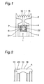
- Fig. 1 is an axial sectional view of a bearing device equipped with a resin-made pulley according to a first embodiment of the present invention.
- This bearing device equipped with a resin-made pulley includes a ball bearing 1 as an example of a rolling bearing, and a phenol resin-made pulley 2 as an example of a resin-made pulley.
- the ball bearing 1 has an outer ring 4, an inner ring 5, and balls 6.
- the balls 6 are provided in a plurality between a raceway groove of the outer ring 4 and a raceway groove of the inner ring 5 so as to be held by a cage 7 and spaced from one another at a constant distance in a circumferential direction.
- Phenol resin which is the material of the phenol resin-made pulley 2, is made by mixing reinforced fiber or glass fiber or spherical silica powder or the like into a base-material resol type phenol resin.
- the phenol resin-made pulley 2 has an inner circumferential surface 11 which is in contact with an outer circumferential surface 10 of the outer ring 4.
- the phenol resin-made pulley 2 and the outer ring 4 are integrally molded by injection molding.
- On the outer circumferential side of the phenol resin-made pulley 2 are formed a plurality of belt fitting grooves 15 to which an unshown belt is to be fitted. It is noted that in Fig. 1, seal members 21, 22 are placed at both axial end portions of the balls 6. These seal members 21, 22 seal the raceway grooves of the outer ring 4 and the inner ring 5 as well as the balls 6 against the outside.
- Fig. 2 is an axial sectional view of the outer ring 4.
- the outer circumferential surface 10 of the outer ring 4 has a cylindrical surface portion 18 and cutout portions (slits) 19.
- the cutout portions 19 are provided two in number at one axial end portion of the outer ring 4 so as to be spaced from each other with a spacing in the circumferential direction of the outer ring 4.
- the cutout portion 19 is opened in the axial direction of the outer ring 4 at its one end.
- the or each cutout portion 19 has a sloped surface 20 which starts from an opening-side axial end of the cutout portion 19 so as to be sloped radially outward of the outer ring 4 progressively with increasing nearness to the axial center and to adjoin the cylindrical surface portion 18 on the other side of the axial direction opposite to the opening side.
- the sloped surface 20 has a generally rectangular shape as viewed from radial outward.
- Fig. 3 is a radial sectional view of the outer ring 4 that runs through the cutout portion 19. As shown in Fig. 3, on circumferential both sides of the sloped surface 20 in a cross section perpendicular to a center axis of the outer ring 4, the cutout portion 19 has side faces 33, 34 generally parallel to a vertical bisector plane 30 of the sloped surface 20 containing the center axis of the outer ring 4.
- the present inventor formed various shapes of recessed portions on the outer circumferential surface of the outer ring, as well as bearing devices equipped with a resin-made pulley by using those outer rings, and looked into the degree of likelihood that creeps would occur in the above bearing devices equipped with a resin-made pulley and having different shapes of the recessed portions.
- a specified magnitude of rotational power applied to each resin-made pulley for a specified time at high temperature whether or not creeps would occur was observed while the resin-made pulley was held rotating at a rotational speed higher than a rated rotational speed, the observation having been done for the following bearing devices equipped with a resin-made pulley.
- a bearing device in which a generally rectangular-in-cross-section cutout portion opened only radially as viewed in the axial sectional view of the outer ring was provided on the outer circumferential surface of the outer ring (hereinafter, referred to as Comparative Example 1), a bearing device in which a dimple-like hole opened only radially as viewed in the axial sectional view of the outer ring was provided on the outer circumferential surface of the outer ring (hereinafter, referred to as Comparative Example 2), a bearing device in which a rectangular-in-cross-section cutout portion opened on radial-and-axial one side of the outer ring as viewed in the axial sectional view of the outer ring and in which the cutout portion had no sloped surface was provided at one end portion of the outer circumferential surface of the outer ring (hereinafter, referred to as Comparative Example 3), a bearing device in which a cutout portion having a bottom face being generally parallel to a cylindrical outer circumferential surface of the outer ring in
- the resin was able to be filled into the cutout portion so as to eliminate any clearances, without occurrence of burning or carbonization around the cutout portion as well as without occurrence of minute creeps.
- a cutout portion having a sloped surface and side faces as described in the first embodiment is formed on the outer ring, the force with which the resin-made pulley clamps the outer ring can be made considerable large so that minute creeps at the rated rotational speed can be prevented and moreover burning and carbonization around the cutout portion can be prevented.
- the reason why even minute creeps do not occur in the bearing device according to the first embodiment is that the bearing device equipped with a resin-made pulley, in which the cutout portion has two side faces generally parallel to the vertical bisector plane of the sloped surface of the cutout portion containing the center axis of the outer ring, is enabled to exert a very large generally circumferential force (normal force) on the resin-made pulley by the two side faces.
- the force with which the phenol resin-made pulley holds the outer ring 4 can be made large, so that creeping of the phenol resin-made pulley at high temperatures can be suppressed as well as occurrence of burning and carbonization around the cutout portion 19 can be prevented.
- the cutout portion 19 has side faces 33, 34 generally parallel to the vertical bisector plane 30 of the sloped surface 20 containing the center axis of the outer ring 4 on circumferential both sides of the sloped surface 20 in a cross section perpendicular to the center axis of the outer ring 4, a generally circumferential force (normal force) can be made to act on the resin-made pulley so that even minute rotations at the rated rotational speed can be prevented.
- two cutout portions 19 are formed with a circumferential spacing from each other at one axial end portion of the outer circumferential surface 10 of the outer ring 4.
- it is also allowed to form one cutout portion at one axial end portion of the outer circumferential surface of the outer ring.
- the pulley 2 made of phenol resin is adopted.
- a resin-made pulley can be made of PPS (polyphenylene sulfide) resin or other resins other than phenol resin.
- the rolling bearing is implemented by a ball bearing 1.
- the rolling bearing may be a roller bearing or the like other than ball bearings.
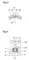
- Fig. 4 is an axial sectional view of a bearing device equipped with a resin-made pulley according to a second embodiment of the present invention.
- the bearing device equipped with a resin-made pulley according to the second embodiment differs from that of the first embodiment only in that its cutout portion has a different shape.
- the same components as those of the bearing device of the first embodiment are designated by the same reference numerals and their detailed description is omitted.
- This bearing device includes a ball bearing 101 as an example of the rolling bearing, and a phenol resin-made pulley 102 as an example of the resin-made pulley.
- the ball bearing 101 has an outer ring 104, an inner ring 5, and balls 6.
- the balls 6 are provided in a plurality between a raceway groove of the outer ring 104 and a raceway groove of the inner ring 5 so as to be held by a cage 7 and spaced from one another at a constant distance in a circumferential direction.
- Phenol resin which is the material of the phenol resin-made pulley 102, is made by mixing reinforced fiber or glass fiber or spherical silica powder or the like into a base-material resol type phenol resin.
- the phenol resin-made pulley 102 has an inner circumferential surface 111 which is in contact with an outer circumferential surface 110 of the outer ring 104.
- the phenol resin-made pulley 102 and the outer ring 104 are integrally molded by injection molding.
- On the outer circumferential side of the phenol resin-made pulley 102 are formed a plurality of belt fitting grooves 115 to which a belt (not shown) is to be fitted.
- Fig. 5 is an axial sectional view of the outer ring 104.
- the outer circumferential surface 110 of the outer ring 104 has a cylindrical surface portion 118 and cutout portions (slits) 119.
- the cutout portions 119 are provided two in number at one axial end portion of the outer ring 104 so as to be spaced from each other with a spacing in the circumferential direction of the outer ring 104.
- the or each cutout portion 119 is opened in the axial direction of the outer ring 104 at its one end.
- a bottom face 120 of the cutout portion 119 has a rectangular shape as viewed from radial outward.
- the bottom face 120 of the cutout portion 119 has a circular-arc shape.
- the bottom face 120 of the cutout portion 119 adjoins to a cylindrical surface portion 118 on its one side of the axial direction opposite to the opening side (i.e., on the inward side of the axial direction).
- a radial distance (precisely, distance in the radial direction of the outer ring 104) between a plane, which contains the center axis of the outer ring 104 and perpendicular to the vertical bisector plane, and the bottom face 120 increases along a direction going inward of the axial direction.
- Fig. 6 is a radial sectional view of the outer ring 104 that runs through the cutout portion 119.
- the cutout portion 119 has, on both sides of the circumferential direction of the bottom face 120 (the circumferential direction of the outer ring 104), side faces 133, 134 generally parallel to the vertical bisector plane 130 of the bottom face 120 containing the center axis of the outer ring 104.
- Fig. 7 is a view for explaining an example of a method for forming the cutout portion 119.
- the cutout portion 119 is formed by, while rotating a circular cutter 200 around its center axis along a direction of arrow a, making the cutter 200 into contact with one axial end portion of the outer circumferential surface of the outer ring 104.
- the present inventor performed the same experiment as that described in the first embodiment also with the bearing device equipped with a resin-made pulley of the second embodiment. Also in the second embodiment, as in the first embodiment, it was verified that the resin was able to be filled into the cutout portion 119 without leaving clearances and without occurrence of burning or carbonization around the cutout portion 119 as well as without occurrence of minute creeps. It was also verified that for the bearing device equipped with a resin-made pulley of the second embodiment, the force with which the resin-made pulley 102 would clamp the outer ring 104 was able to be further enhanced, as compared with the bearing device equipped with a resin-made pulley of the first embodiment.
- the cutout portion 119 having the bottom face 120 which has a circular-arc shape as viewed in an axial sectional view of the outer ring 104 sectioning through the cutout portion 119 and which adjoins the cylindrical surface portion 118 on the inward side of the axial direction, is formed at one axial end portion of the outer circumferential surface of the outer ring 104. Therefore, a resin flow that runs along the bottom face 120 can be generated during the resin molding process so that the resin can be filled into the cutout portion 119 without leaving any clearances.
- the force with which the resin-made pulley 102 clamps the outer ring 104 can be made larger, so that creeping of the phenol resin-made pulley 102 at high temperatures can be suppressed.
- the cutout portion 119 has, on circumferential both sides of the bottom face 120, the side faces 133, 134 generally parallel to the vertical bisector plane of the bottom face 120 containing the center axis of the outer ring 104, so that a generally circumferential force (normal force) can be made to act on the resin-made pulley 102.
- a generally circumferential force normal force
- the resin-made pulley 102 against the outer ring 104 can also be prevented at normal rotational speeds such as the rated rotational speed.
- the bottom face 120 has a circular-arc shape, as viewed in an axial sectional view of the outer ring 104 sectioning through the cutout portion 119. Therefore, a larger amount of the resin can be filled into the cutout portion 119, as compared with the first embodiment, in which the sloped surface 20, which is the bottom face, has a linear shape as viewed in the axial sectional view of the outer ring 4 sectioning through the cutout portion 19. Thus, the force with which the resin-made pulley 102 clamps the outer ring 104 can be made even larger.
- the cutout portion 119 can be formed with simplicity and low cost only by making the circular cutter 200 into contact with one axial end portion of the outer circumferential surface of the outer ring 104. Moreover, since the cutout portion 119 can be formed in short time, allowing the cycle time to be shortened, the productivity for the product can be improved to a great extent.
- two cutout portions 119 are formed with a circumferential spacing from each other at one axial end portion of the outer circumferential surface 110 of the outer ring 104.
- one cutout portion is formed at one axial end portion of, the outer circumferential surface of the outer ring.
- three or more cutout portions may also be formed with circumferential spacings from one another at one axial end portion of the outer circumferential surface of the outer ring.
- cutout portions may be formed at both axial end portions of the outer circumferential surface of the outer ring.
- the pulley 2 made of phenol resin is adopted.
- a resin-made pulley can be made of PPS (polyphenylene sulfide) resin or other resins other than phenol resin.
- the rolling bearing is implemented by a ball bearing 101.
- the rolling bearing may be a roller bearing or the like other than ball bearings.
Landscapes
- Engineering & Computer Science (AREA)
- General Engineering & Computer Science (AREA)
- Mechanical Engineering (AREA)
- Manufacturing & Machinery (AREA)
- Pulleys (AREA)
- Mounting Of Bearings Or Others (AREA)
- Rolling Contact Bearings (AREA)
Applications Claiming Priority (2)
| Application Number | Priority Date | Filing Date | Title |
|---|---|---|---|
| JP2006094137 | 2006-03-30 | ||
| JP2007013983A JP2007292287A (ja) | 2006-03-30 | 2007-01-24 | 樹脂製プーリ付軸受装置 |
Publications (3)
| Publication Number | Publication Date |
|---|---|
| EP1840412A2 true EP1840412A2 (de) | 2007-10-03 |
| EP1840412A3 EP1840412A3 (de) | 2008-05-21 |
| EP1840412B1 EP1840412B1 (de) | 2012-03-21 |
Family
ID=38191137
Family Applications (1)
| Application Number | Title | Priority Date | Filing Date |
|---|---|---|---|
| EP07006532A Not-in-force EP1840412B1 (de) | 2006-03-30 | 2007-03-29 | Tragevorrichtung mit Riemenscheibe aus Harz |
Country Status (3)
| Country | Link |
|---|---|
| US (1) | US20070232428A1 (de) |
| EP (1) | EP1840412B1 (de) |
| JP (1) | JP2007292287A (de) |
Cited By (1)
| Publication number | Priority date | Publication date | Assignee | Title |
|---|---|---|---|---|
| EP3287298A1 (de) * | 2016-08-22 | 2018-02-28 | DT Swiss AG | Nabe und nabenserie |
Families Citing this family (8)
| Publication number | Priority date | Publication date | Assignee | Title |
|---|---|---|---|---|
| JP2008213393A (ja) * | 2007-03-07 | 2008-09-18 | Jtekt Corp | 樹脂巻き部品 |
| JP2012102799A (ja) * | 2010-11-10 | 2012-05-31 | Honda Motor Co Ltd | ウォーム減速装置 |
| WO2013168889A1 (ko) * | 2012-05-08 | 2013-11-14 | 한라비스테온공조 주식회사 | 압축기용 풀리 어셈블리 및 그 제조 방법 |
| JP2014149042A (ja) * | 2013-02-01 | 2014-08-21 | Nihon Isued Corp | 合成樹脂製プーリ |
| DE102016208286A1 (de) * | 2015-05-28 | 2016-12-01 | Robert Bosch Gmbh | Rollenlager und hydrostatische Axialkolbenmaschine in Schrägscheibenbauweise mit einem Rollenlager |
| US9845860B2 (en) * | 2015-07-20 | 2017-12-19 | Dayco Ip Holdings, Llc | Retaining clamp for molded plastics |
| JP7394738B2 (ja) * | 2020-11-05 | 2023-12-08 | 住友重機械工業株式会社 | 減速装置 |
| US12276327B2 (en) * | 2021-01-15 | 2025-04-15 | Jtekt Corporation | Toothed pulley |
Citations (1)
| Publication number | Priority date | Publication date | Assignee | Title |
|---|---|---|---|---|
| FR2605070A1 (fr) | 1986-10-09 | 1988-04-15 | Skf Gmbh | Piece de machine annulaire en particulier galet a roulement |
Family Cites Families (13)
| Publication number | Priority date | Publication date | Assignee | Title |
|---|---|---|---|---|
| DE1782485U (de) * | 1958-11-19 | 1959-02-05 | Schneider G M B H Metallwarenf | Kugellager. |
| JPS461690Y1 (de) * | 1967-06-30 | 1971-01-21 | ||
| JPS5016353A (de) * | 1973-06-15 | 1975-02-20 | ||
| DE2611218A1 (de) * | 1976-03-17 | 1977-10-06 | Kugelfischer G Schaefer & Co | Form- und kraftschluessige verbindung von waelzlagerteilen mit umgebungsteilen |
| US4046432A (en) * | 1976-06-09 | 1977-09-06 | Fidelity Electric Company, Incorporated | Bearing assembly and anchor therefor |
| US6129455A (en) * | 1998-11-10 | 2000-10-10 | Ford Motor Company | Bearing assembly |
| DE10001575C2 (de) * | 2000-01-15 | 2003-01-02 | Skf Gmbh | Verfahren zur Fixierung wenigstens eines Lagers in einer Lageraufnahme |
| JP2001317616A (ja) * | 2000-05-10 | 2001-11-16 | Koyo Seiko Co Ltd | 軸受付き樹脂プーリ |
| FR2809791B1 (fr) * | 2000-06-06 | 2002-08-23 | Skf France | Galet tendeur de courroie |
| JP2002195388A (ja) * | 2000-12-26 | 2002-07-10 | Toyoda Mach Works Ltd | プーリ装置 |
| US6666583B2 (en) * | 2001-12-04 | 2003-12-23 | Visteon Global Technologies, Inc. | Bearing retention assembly having cam chamfered bearing race ring |
| JP2003207032A (ja) * | 2002-01-15 | 2003-07-25 | Denso Corp | 回転体 |
| JP2004028275A (ja) * | 2002-06-27 | 2004-01-29 | Nsk Ltd | 軸受一体型樹脂プーリ |
-
2007
- 2007-01-24 JP JP2007013983A patent/JP2007292287A/ja active Pending
- 2007-03-28 US US11/727,842 patent/US20070232428A1/en not_active Abandoned
- 2007-03-29 EP EP07006532A patent/EP1840412B1/de not_active Not-in-force
Patent Citations (1)
| Publication number | Priority date | Publication date | Assignee | Title |
|---|---|---|---|---|
| FR2605070A1 (fr) | 1986-10-09 | 1988-04-15 | Skf Gmbh | Piece de machine annulaire en particulier galet a roulement |
Cited By (1)
| Publication number | Priority date | Publication date | Assignee | Title |
|---|---|---|---|---|
| EP3287298A1 (de) * | 2016-08-22 | 2018-02-28 | DT Swiss AG | Nabe und nabenserie |
Also Published As
| Publication number | Publication date |
|---|---|
| JP2007292287A (ja) | 2007-11-08 |
| US20070232428A1 (en) | 2007-10-04 |
| EP1840412A3 (de) | 2008-05-21 |
| EP1840412B1 (de) | 2012-03-21 |
Similar Documents
| Publication | Publication Date | Title |
|---|---|---|
| EP1840412B1 (de) | Tragevorrichtung mit Riemenscheibe aus Harz | |
| US8523450B2 (en) | Ball bearing and hybrid vehicle transmission | |
| CN108397476B (zh) | 滚珠轴承 | |
| EP2754907B1 (de) | Wälzlagerkäfig und wälzlager | |
| EP3255293B1 (de) | Wälzlagerhalter, wälzlager und verfahren zur herstellung des wälzlagerhalters | |
| US8292512B2 (en) | Ball bearing and supporting construction | |
| EP2620663B1 (de) | Wälzlager | |
| EP2559906A1 (de) | Halter für ein kegelförmiges kugellager, verfahren zur herstellung des halters und kegelförmiges kugellager | |
| KR102013084B1 (ko) | 원추 롤러 베어링 및 원추 롤러 베어링의 제조 방법 | |
| EP3290724B1 (de) | Anlaufscheiben mit hydrodynamischen merkmalen | |
| TWI620880B (zh) | 斜角滾珠軸承 | |
| WO2015029851A1 (ja) | 玉軸受用保持器 | |
| TW201819787A (zh) | 保持器及具備其之滾動軸承 | |
| JP2022036002A (ja) | 玉軸受 | |
| JP2010090969A (ja) | 樹脂プーリ付き軸受 | |
| US9145917B2 (en) | Cage for radial roller bearing | |
| US20140145366A1 (en) | Fluid dynamic bearing device | |
| JP2009228752A (ja) | 円筒ころ軸受用保持器 | |
| KR102445802B1 (ko) | 볼베어링용 유지기 | |
| JP5715001B2 (ja) | ラジアル玉軸受 | |
| US12292081B2 (en) | Ball bearing | |
| JP2009127755A (ja) | 樹脂製プーリ付軸受装置 | |
| JP2011137517A (ja) | 樹脂製プーリ | |
| JP7660002B2 (ja) | 保持器及び玉軸受 | |
| JP7724145B2 (ja) | シール付玉軸受 |
Legal Events
| Date | Code | Title | Description |
|---|---|---|---|
| PUAI | Public reference made under article 153(3) epc to a published international application that has entered the european phase |
Free format text: ORIGINAL CODE: 0009012 |
|
| AK | Designated contracting states |
Kind code of ref document: A2 Designated state(s): AT BE BG CH CY CZ DE DK EE ES FI FR GB GR HU IE IS IT LI LT LU LV MC MT NL PL PT RO SE SI SK TR |
|
| AX | Request for extension of the european patent |
Extension state: AL BA HR MK YU |
|
| PUAL | Search report despatched |
Free format text: ORIGINAL CODE: 0009013 |
|
| AK | Designated contracting states |
Kind code of ref document: A3 Designated state(s): AT BE BG CH CY CZ DE DK EE ES FI FR GB GR HU IE IS IT LI LT LU LV MC MT NL PL PT RO SE SI SK TR |
|
| AX | Request for extension of the european patent |
Extension state: AL BA HR MK RS |
|
| 17P | Request for examination filed |
Effective date: 20081121 |
|
| AKX | Designation fees paid |
Designated state(s): DE FR |
|
| 17Q | First examination report despatched |
Effective date: 20101209 |
|
| REG | Reference to a national code |
Ref country code: DE Ref legal event code: R079 Ref document number: 602007021395 Country of ref document: DE Free format text: PREVIOUS MAIN CLASS: F16H0055360000 Ipc: F16H0055480000 |
|
| RIC1 | Information provided on ipc code assigned before grant |
Ipc: F16H 55/48 20060101AFI20110830BHEP |
|
| GRAP | Despatch of communication of intention to grant a patent |
Free format text: ORIGINAL CODE: EPIDOSNIGR1 |
|
| GRAS | Grant fee paid |
Free format text: ORIGINAL CODE: EPIDOSNIGR3 |
|
| GRAA | (expected) grant |
Free format text: ORIGINAL CODE: 0009210 |
|
| AK | Designated contracting states |
Kind code of ref document: B1 Designated state(s): DE FR |
|
| REG | Reference to a national code |
Ref country code: DE Ref legal event code: R096 Ref document number: 602007021395 Country of ref document: DE Effective date: 20120516 |
|
| PLBE | No opposition filed within time limit |
Free format text: ORIGINAL CODE: 0009261 |
|
| STAA | Information on the status of an ep patent application or granted ep patent |
Free format text: STATUS: NO OPPOSITION FILED WITHIN TIME LIMIT |
|
| 26N | No opposition filed |
Effective date: 20130102 |
|
| REG | Reference to a national code |
Ref country code: DE Ref legal event code: R097 Ref document number: 602007021395 Country of ref document: DE Effective date: 20130102 |
|
| REG | Reference to a national code |
Ref country code: FR Ref legal event code: PLFP Year of fee payment: 9 |
|
| PGFP | Annual fee paid to national office [announced via postgrant information from national office to epo] |
Ref country code: FR Payment date: 20150309 Year of fee payment: 9 |
|
| REG | Reference to a national code |
Ref country code: FR Ref legal event code: ST Effective date: 20161130 |
|
| PG25 | Lapsed in a contracting state [announced via postgrant information from national office to epo] |
Ref country code: FR Free format text: LAPSE BECAUSE OF NON-PAYMENT OF DUE FEES Effective date: 20160331 |
|
| PGFP | Annual fee paid to national office [announced via postgrant information from national office to epo] |
Ref country code: DE Payment date: 20230131 Year of fee payment: 17 |
|
| REG | Reference to a national code |
Ref country code: DE Ref legal event code: R119 Ref document number: 602007021395 Country of ref document: DE |
|
| PG25 | Lapsed in a contracting state [announced via postgrant information from national office to epo] |
Ref country code: DE Free format text: LAPSE BECAUSE OF NON-PAYMENT OF DUE FEES Effective date: 20241001 |
|
| PG25 | Lapsed in a contracting state [announced via postgrant information from national office to epo] |
Ref country code: DE Free format text: LAPSE BECAUSE OF NON-PAYMENT OF DUE FEES Effective date: 20241001 |