EP1840439B1 - Klemmvorrichtung - Google Patents
Klemmvorrichtung Download PDFInfo
- Publication number
- EP1840439B1 EP1840439B1 EP07251043A EP07251043A EP1840439B1 EP 1840439 B1 EP1840439 B1 EP 1840439B1 EP 07251043 A EP07251043 A EP 07251043A EP 07251043 A EP07251043 A EP 07251043A EP 1840439 B1 EP1840439 B1 EP 1840439B1
- Authority
- EP
- European Patent Office
- Prior art keywords
- members
- clamping device
- clamped
- unclamped
- clamping
- Prior art date
- Legal status (The legal status is an assumption and is not a legal conclusion. Google has not performed a legal analysis and makes no representation as to the accuracy of the status listed.)
- Active
Links
Images


Classifications
-
- F—MECHANICAL ENGINEERING; LIGHTING; HEATING; WEAPONS; BLASTING
- F16—ENGINEERING ELEMENTS AND UNITS; GENERAL MEASURES FOR PRODUCING AND MAINTAINING EFFECTIVE FUNCTIONING OF MACHINES OR INSTALLATIONS; THERMAL INSULATION IN GENERAL
- F16L—PIPES; JOINTS OR FITTINGS FOR PIPES; SUPPORTS FOR PIPES, CABLES OR PROTECTIVE TUBING; MEANS FOR THERMAL INSULATION IN GENERAL
- F16L23/00—Flanged joints
- F16L23/04—Flanged joints the flanges being connected by members tensioned in the radial plane
- F16L23/08—Flanged joints the flanges being connected by members tensioned in the radial plane connection by tangentially arranged pin and nut
-
- F—MECHANICAL ENGINEERING; LIGHTING; HEATING; WEAPONS; BLASTING
- F16—ENGINEERING ELEMENTS AND UNITS; GENERAL MEASURES FOR PRODUCING AND MAINTAINING EFFECTIVE FUNCTIONING OF MACHINES OR INSTALLATIONS; THERMAL INSULATION IN GENERAL
- F16L—PIPES; JOINTS OR FITTINGS FOR PIPES; SUPPORTS FOR PIPES, CABLES OR PROTECTIVE TUBING; MEANS FOR THERMAL INSULATION IN GENERAL
- F16L21/00—Joints with sleeve or socket
- F16L21/06—Joints with sleeve or socket with a divided sleeve or ring clamping around the pipe ends
- F16L21/065—Joints with sleeve or socket with a divided sleeve or ring clamping around the pipe ends tightened by tangentially-arranged threaded pins
-
- F—MECHANICAL ENGINEERING; LIGHTING; HEATING; WEAPONS; BLASTING
- F01—MACHINES OR ENGINES IN GENERAL; ENGINE PLANTS IN GENERAL; STEAM ENGINES
- F01N—GAS-FLOW SILENCERS OR EXHAUST APPARATUS FOR MACHINES OR ENGINES IN GENERAL; GAS-FLOW SILENCERS OR EXHAUST APPARATUS FOR INTERNAL-COMBUSTION ENGINES
- F01N13/00—Exhaust or silencing apparatus characterised by constructional features
- F01N13/18—Construction facilitating manufacture, assembly, or disassembly
- F01N13/1838—Construction facilitating manufacture, assembly, or disassembly characterised by the type of connection between parts of exhaust or silencing apparatus, e.g. between housing and tubes, between tubes and baffles
- F01N13/1844—Mechanical joints
- F01N13/1855—Mechanical joints the connection being realised by using bolts, screws, rivets or the like
-
- F—MECHANICAL ENGINEERING; LIGHTING; HEATING; WEAPONS; BLASTING
- F01—MACHINES OR ENGINES IN GENERAL; ENGINE PLANTS IN GENERAL; STEAM ENGINES
- F01N—GAS-FLOW SILENCERS OR EXHAUST APPARATUS FOR MACHINES OR ENGINES IN GENERAL; GAS-FLOW SILENCERS OR EXHAUST APPARATUS FOR INTERNAL-COMBUSTION ENGINES
- F01N13/00—Exhaust or silencing apparatus characterised by constructional features
- F01N13/18—Construction facilitating manufacture, assembly, or disassembly
- F01N13/1872—Construction facilitating manufacture, assembly, or disassembly the assembly using stamp-formed parts or otherwise deformed sheet-metal
-
- F—MECHANICAL ENGINEERING; LIGHTING; HEATING; WEAPONS; BLASTING
- F02—COMBUSTION ENGINES; HOT-GAS OR COMBUSTION-PRODUCT ENGINE PLANTS
- F02B—INTERNAL-COMBUSTION PISTON ENGINES; COMBUSTION ENGINES IN GENERAL
- F02B67/00—Engines characterised by the arrangement of auxiliary apparatus not being otherwise provided for, e.g. the apparatus having different functions; Driving auxiliary apparatus from engines, not otherwise provided for
- F02B67/10—Engines characterised by the arrangement of auxiliary apparatus not being otherwise provided for, e.g. the apparatus having different functions; Driving auxiliary apparatus from engines, not otherwise provided for of charging or scavenging apparatus
Definitions
- This invention relates to a clamping device for clamping two or more articles together.
- a G-clamp comprising two semi-circular segments hinged together at a first end to allow the segments to pivot relative to each other between clamped and unclamped positions.
- the second or free ends of the segments can be engaged together via a nut and bolt to maintain the segments in the clamped position.
- the flanged portions of the turbo charger and the exhaust pipe are brought into abutting relationship and held together via a first user in a required position.
- a second user locates the members of the G-clamp around the flanged portions and moves the engagement nut and bolt into engagement position to clamp the G-clamp around the flanged portions.
- US6030006 discloses a spring biased clamping device for flanged connections.
- the clamp device have a plurality of arcuate segment and a pivot couples at least one end of each arcuate segment to another of the arcuate segments.
- a torsion spring is disposed around each pivot to bias the arcuate segments into the configuration that produces an annular structure.
- a rocking bolt is provided at the free ends of the segments and a biasing element biases the rocking bolt into a required position.
- US4657284 discloses a remotely manipulatable clamp for clamping two pipes together.
- the clamp comprises two members articulated about a common pin. One end of the members are joined via a rocking bolt and the other end of the members is provided with a compression spring for closing the clamp.
- US6056332 discloses clamping apparatus for engaging a pair of abutting flanges of two pipes.
- the apparatus includes first and second clamp portions joined to a pivot end at one end of the members and a rocking bolt is provided at the other end of the members to join the same together.
- a spring wire is engaged with the clamping portions to bias the clamping portions to a closed position.
- US4730850 discloses a quick release coupling device for securing end flanges of two adjacent pipes together.
- the device includes a plurality of clamping members, each member having a spring to resiliently urge the clamping members outwardly of the end flanges.
- Each clamping member also has connecting members for connecting adjacent pairs of clamping members together so as to form an annulus with a gap between two end clamping members.
- Coupling means are disposed in the gap for releasably connecting one end to the other end against the bias of the clamping members.
- US2003/0116967 discloses a self aligning coupling assembly for mating a pair of corresponding flanged pipe ends together.
- the coupling comprises first and second arms pivotally connected to each other at one end.
- a flange fitting is provided on one of the pipe ends on which the coupling is to be used and the first and second arm members are located adjacent to the flange fitting in use.
- a garter spring is provided around the first and second arms to bias the arms to a closed position around the pipe ends.
- Movement of the members from the unclamped position to the clamped position typically reduces the diameter or dimensions defined by or within said members, thereby allowing clamping of two or more articles located within said clamping members.
- at least one aperture can be defined by or between said members and the dimensions of said aperture are reduced when said device moves from said unclamped to said clamped position.
- the resilient biasing means are provided over, across or are associated with the connection point or points connecting the two or more members together, such as for example, over the hinge joining the two members together.
- the biasing means typically provide a compressive force over or across the connection means of the members biasing the members together.
- Engagement means are provided to maintain the members in at least a clamped position.
- the engagement means can be associated with the connection means, link plate and/or hinge or pivot connection but preferably the engagement means are associated with free ends of the members, and preferably opposite to the hinge or pivot connection.
- the engagement means can, in one embodiment be used to maintain the members in an unclamped position.
- the engagement means can include any or any combination of one or more clips, ties, welding, adhesive, nut and bolt, screw and/or the like.
- separation means are provided to maintain said members in an unclamped position.
- the separation means are provided between the free ends of the two or more members.
- the separation means are detachably attached to the device or to one or more members of the device, such that removal of said separation means moves the members from an unclamped position to a clamped position under the bias of the resilient biasing means.
- the separation means are of such a form so as to provide sufficient force to overcome the bias of the resilient biasing means when fitted to the device.
- the resilient biasing means can be attached to the device via any suitable means, such as adhesive, welding, one or more screws, nut & bolt, inter-engaging means and/or the like. In one embodiment the resilient biasing means are detachably attached to said device.
- the clamping device is provided with mounting means for allowing the device to be mounted in, on or with respect to a required position or surface in use.
- the device is typically mounted prior to movement of the device from the unclamped to the clamped position.
- the mounting means is in the form of or includes a plate, such as a weld plate, to allow the device to be welded in a required location prior to actuation of the clamping device.
- the clamping device is in the form of a G-clamp with two substantially semi-circular members, the two members being preferably hingedly connected together.
- the mounting means allows the clamping device to be mounted to a suitable surface in the locality in which it is to be fitted prior to moving the clamping device between unclamped and clamped positions. As such, a user can mount the device and then have their hands free to actuate the clamping device and/or move the two articles together with respect to the clamping device to a required position without the need to have an additional user to help fit the same.
- the mounting means and resilient biasing means can be used independently of each other or in combination with each other to provide an improved clamping device.
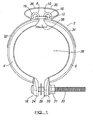
- First and second members 4, 6 are hingedly connected at ends 8, 10 thereof via a link member 12 having slots 14 defined therein for location of ends 8, 10 therethrough.
- the free ends 8, 10 are formed into a hook 16 to prevent removal of the same from link member 12.
- members 4, 6 can be pivoted about link member 12 between clamped and unclamped positions.
- ends 18, 20 are a spaced distance apart and the dimensions of aperture 28 are relatively large, thereby allowing members 4, 6 to be located around two flanged articles.
- ends 18, 20 are moved towards each other such that they engage, abut or are a smaller distance apart than in the unclamped position to allow the two flanged articles to be secured together.
- the dimensions of aperture 28 are reduced, thereby providing a clamping force on the two flanged articles around which the device is placed.
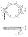
- Separation means are located between end plates 24, 26 of members 4, 6 to maintain the members in an unclamped position if required during the process of fitting the clamping device around the articles.
- the separation means are detachably attached to the device or member(s) to allow easy removal of the same.
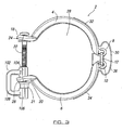
- the separation means are in addition to the engagement means associated with the end plates. An example of separation means is described in more detail below with reference to figure 3 .
- mounting means in the form of a welding plate 38.
- Welding plate 38 protrudes outwardly of the device to allow the device to be welded relative to one or both of the articles to be joined together in use.
- the members can be formed or any suitable material and can be of any shape to define an aperture of any suitable size or shape.
- the resilient biasing means can also be of any suitable size, shape and design and in the illustrated example of the present invention is formed of sprung stainless steel so as to withstand relatively high temperatures associated with the application of joining a turbo charger of a motor vehicle to an exhaust pipe.
- a user welds the weld plate 38 to a suitable surface and moves the device to the unclamped position.
- the user brings the two flanged articles together in a required position and/or orientation, such that the parts of the articles to be joined are located through the aperture defined by the clamping members. Whilst holding the articles in place, the user removes the separation means holding the members in an unclamped position and the bias of the resilient biasing means moves the members to a clamped position around the articles.
- G-Clamp 2 is illustrated with separation means in the form of a clip 102 which acts to maintain ends 18, 20 of members 4, 6 in an unclamped position More particularly, clip 102 has a first end 104 clipped to a portion of bolt 22 between ends 18, 20, and preferably abutting inner surface of end 20, and a second end 106 abutting against nut 21. The nut 21 also abuts against outer surface of end 20.
- a U-shaped linking arm 108 is provided between ends 104, 106. Arm 108 is typically U-shaped so as to avoid any obstruction or interference with end 26 of member 6 but it could be any suitable shape.
Landscapes
- Engineering & Computer Science (AREA)
- General Engineering & Computer Science (AREA)
- Mechanical Engineering (AREA)
- Clamps And Clips (AREA)
- Jigs For Machine Tools (AREA)
- Electrical Discharge Machining, Electrochemical Machining, And Combined Machining (AREA)
Claims (21)
- Klemmvorrichtung (2) zum Zusammenklemmen von zwei oder mehr Artikeln, wobei die genannte Klemmvorrichtung zwei oder mehr Elemente (4, 6) hat, die zwischen einer gelösten Position und einer festgeklemmten Position bewegbar sind, federnde Vorspannmittel (30) an der genannten Klemmvorrichtung (2) bereitgestellt oder mit ihr assoziiert sind, um die zwei oder mehr Elemente (4, 6) im Gebrauch auf die genannte festgeklemmte Position vorzuspannen, und Eingriffsmittel (21, 22) bereitgestellt sind, um die Elemente (4, 6) in der festgeklemmten Position zu halten, dadurch gekennzeichnet, dass die Klemmvorrichtung zusätzlich zu den Eingriffsmitteln (21, 22) Trennvorrichtungen (102) aufweist, um die Elemente (4, 6) und die Eingriffsmittel (21, 22) in der gelösten Stellung zu halten, und wobei die genannten Trennvorrichtungen (102) abnehmbar an der Vorrichtung (2) angebracht sind, so dass das Entfernen der Trennvorrichtungen (102) von der Vorrichtung (2) die Elemente (4, 6) unter der Vorspannung der federnden Vorspannmittel (30) von der gelösten Position in die festgeklemmte Position bewegt.
- Klemmvorrichtung nach Anspruch 1, dadurch gekennzeichnet, dass in der gelösten Position ein oder mehrere Enden (18, 20) eines Elements (4, 6) um einen Abstand von einem oder mehreren Enden eines benachbarten Elements beabstandet ist bzw. sind.
- Klemmvorrichtung nach Anspruch 2, dadurch gekennzeichnet, dass in der festgeklemmten Position die Enden (18, 20) der Elemente (4, 6) miteinander in Eingriff bewegt werden, in aneinanderstoßender Beziehung zueinander und/oder so bewegt werden, dass ein Abstand zwischen den Enden im Vergleich zu dem in der gelösten Position verringert wird.
- Klemmvorrichtung nach Anspruch 1, dadurch gekennzeichnet, dass wenigstens eine Öffnung (28) von oder zwischen den zwei oder mehr Elementen (4, 6) definiert wird und die Maße der genannten Öffnung reduziert werden, während die Vorrichtung von der gelösten Position in die festgeklemmte Position bewegt wird.
- Klemmvorrichtung nach Anspruch 1, dadurch gekennzeichnet, dass die zwei oder mehr Elemente (4, 6) entweder direkt oder indirekt gelenkig oder drehbar miteinander verbunden sind, um das Drehen bzw. Schwenken der genannten Elemente zwischen der genannten festgeklemmten und gelösten Position zuzulassen.
- Klemmvorrichtung nach Anspruch 1, dadurch gekennzeichnet, dass die zwei oder mehr Elemente (4, 6) über ein Verbindungsglied (12) beweglich aneinander montiert sind.
- Klemmvorrichtung nach Anspruch 6, dadurch gekennzeichnet, dass in dem Verbindungsglied (12) eine oder mehrere Öffnungen (14) definiert sind und jedes Ende (8, 10) jedes Elements (4, 6) beweglich in der/den genannten einen oder mehreren Öffnungen montiert ist.
- Klemmvorrichtung nach Anspruch 1, dadurch gekennzeichnet, dass die zwei oder mehr Elemente (4, 6) durch Verbindungsmittel miteinander verbunden sind und die genannten Verbindungsmittel beweglich sind, so dass die Elemente sich zwischen der genannten festgeklemmten und gelösten Position bewegen können.
- Klemmvorrichtung nach Anspruch 1, dadurch gekennzeichnet, dass das federnde Vorspannmittel (30) beliebig eine oder mehrere Federn, federndes Material, elastisches Material oder Gummi oder eine beliebige Kombination von diesen aufweist.
- Klemmvorrichtung nach Anspruch 1, dadurch gekennzeichnet, dass die federnden Vorspannmittel (30) auf, über oder in Assoziation mit dem/den Verbindungspunkt oderpunkten bereitgestellt sind, der/die die zwei oder mehr Elemente (4, 6) miteinander verbindet/verbinden.
- Klemmvorrichtung nach Anspruch 1, dadurch gekennzeichnet, dass die Eingriffsmittel mit den freien Enden (18, 20) der Elemente (4, 6) assoziiert sind.
- Klemmvorrichtung nach Anspruch 1, dadurch gekennzeichnet, dass das Eingriffsmittel eine Mutter und Schraube (21, 22) ist.
- Klemmvorrichtung nach Anspruch 1, dadurch gekennzeichnet, dass sich die Trennvorrichtungen zwischen den freien Enden (18, 20) der genannten Elemente (4, 6) befinden.
- Klemmvorrichtung nach Anspruch 1, dadurch gekennzeichnet, dass die Trennvorrichtung ein oder mehrere Klammern (102) aufweist.
- Klemmvorrichtung nach Anspruch 1, dadurch gekennzeichnet, dass die federnden Vorspannmittel durch Schweißen, Klebstoff, eine oder mehrere Schrauben, Mutter und Schraube und/oder ineinandergreifende Mittel an der Vorrichtung (2) angebracht sind.
- Klemmvorrichtung nach Anspruch 1, dadurch gekennzeichnet, dass Befestigungsmittel bereitgestellt sind, so dass die Vorrichtung im Gebrauch an einer gewünschten Position an oder im Verhältnis zu einem Artikel oder einer Oberfläche montiert werden kann.
- Klemmvorrichtung nach Anspruch 16, dadurch gekennzeichnet, dass die Befestigungsmittel von einer Oberfläche der Vorrichtung nach außen vorstehen.
- Klemmvorrichtung nach Anspruch 17, dadurch gekennzeichnet, dass das Befestigungsmittel die Form einer Platte (38) hat.
- Klemmvorrichtung nach Anspruch 1, dadurch gekennzeichnet, dass die Vorrichtung (2) die Form einer Schraubzwinge mit zwei im Wesentlichen halbkreisförmigen Elementen (4, 6) hat.
- Klemmvorrichtung nach Anspruch 1, dadurch gekennzeichnet, dass das Eingriffsmittel die Form einer Mutter und Schraube (21, 22) hat und die Trennvorrichtung die Form einer Klammer (102) hat, wobei im Gebrauch in der gelösten Position ein erstes Ende (104) der Klammer an die Schraube geklemmt ist und ein zweites Ende (106) der Klammer an der Mutter in Anlage ist.
- Verfahren zur Verwendung einer Klemmvorrichtung (2) zum Zusammenklemmen von zwei oder mehr Artikeln, wobei die genannte Klemmvorrichtung zwei oder mehr Elemente (4, 6) hat, die zwischen einer gelösten Position und einer festgeklemmten Position bewegbar sind, und wobei das genannte Verfahren die Schritte des Ansetzens der Vorrichtung (2) um die genannten Artikel, die festgeklemmt werden, und des Bewegenlassens der genannten Elemente (4, 6) unter der federnden Vorspannkraft von federnden Vorspannmitteln (30), die an der genannten Klemmvorrichtung (2) bereitgestellt oder mit ihr assoziiert sind, von der genannten gelösten Position in die genannte festgeklemmte Position, des Entfernens der Trennvorrichtungen (102) von der Vorrichtung (2), die zum Halten der Elemente (4, 6) und der Eingriffsmittel (30) in der gelösten Position verwendet werden, so dass die Vorrichtung (2) die Elemente (4, 6) unter der Vorspannung der federnden Vorspannmittel (30) von der gelösten Position in die festgeklemmte Position bewegt, und des Verwendens von Eingriffsmitteln (21, 22) zum Halten der Elemente (4, 6) in der festgeklemmten Position aufweist.
Applications Claiming Priority (1)
| Application Number | Priority Date | Filing Date | Title |
|---|---|---|---|
| GBGB0606299.6A GB0606299D0 (en) | 2006-03-30 | 2006-03-30 | Clamping device |
Publications (3)
| Publication Number | Publication Date |
|---|---|
| EP1840439A2 EP1840439A2 (de) | 2007-10-03 |
| EP1840439A3 EP1840439A3 (de) | 2007-11-28 |
| EP1840439B1 true EP1840439B1 (de) | 2010-06-16 |
Family
ID=36424819
Family Applications (1)
| Application Number | Title | Priority Date | Filing Date |
|---|---|---|---|
| EP07251043A Active EP1840439B1 (de) | 2006-03-30 | 2007-03-14 | Klemmvorrichtung |
Country Status (4)
| Country | Link |
|---|---|
| EP (1) | EP1840439B1 (de) |
| AT (1) | ATE471479T1 (de) |
| DE (1) | DE602007007138D1 (de) |
| GB (1) | GB0606299D0 (de) |
Cited By (5)
| Publication number | Priority date | Publication date | Assignee | Title |
|---|---|---|---|---|
| USD695100S1 (en) | 2011-10-18 | 2013-12-10 | Nordson Corporation | Clamp for a sanitary fitting |
| CN107076004A (zh) * | 2014-09-04 | 2017-08-18 | 卡约企业公司 | 用于耦接两个管的系统 |
| WO2017200903A1 (en) * | 2016-05-16 | 2017-11-23 | Victaulic Company | Sprung coupling |
| US10273996B2 (en) | 2011-03-07 | 2019-04-30 | Nordson Corporation | Clamp for sanitary fitting |
| RU2738985C2 (ru) * | 2016-10-04 | 2020-12-21 | Этаблиссман Кайо | Зажимное устройство для соединения двух труб с регулируемым угловым позиционированием |
Families Citing this family (14)
| Publication number | Priority date | Publication date | Assignee | Title |
|---|---|---|---|---|
| DE102009039862B4 (de) | 2009-09-03 | 2013-04-18 | Norma Germany Gmbh | Profilschelle |
| ITVR20090198A1 (it) | 2009-11-19 | 2011-05-20 | Alteco S R L | Sistema di chiusura per contenitori metallici e/o tubazioni in pressione |
| EP2674656B1 (de) * | 2012-06-14 | 2016-08-10 | NORMA Germany GmbH | Profilschelle |
| DE202013001224U1 (de) * | 2013-02-07 | 2013-02-15 | Norma Germany Gmbh | Profilschelle mit Vorpositionierer |
| US10578234B2 (en) | 2013-05-02 | 2020-03-03 | Victaulic Company | Coupling having arcuate stiffness ribs |
| GB2528094B (en) * | 2014-07-09 | 2017-04-26 | Jaguar Land Rover Ltd | Improved fastening device |
| DE102014113165A1 (de) * | 2014-09-12 | 2016-03-17 | Ihi Charging Systems International Gmbh | Abgasturbolader |
| DK3397884T3 (da) | 2015-12-28 | 2020-08-03 | Victaulic Co Of America | Adapterkobling |
| DE102016103986B3 (de) * | 2016-03-04 | 2017-08-24 | Norma Germany Gmbh | Vorpositionierer für eine Profilschelle und Verbindungsanordnung mit einem derartigen Vorpositionierer |
| US10533688B2 (en) | 2016-05-16 | 2020-01-14 | Victaulic Company | Coupling having tabbed retainer |
| US10605394B2 (en) | 2016-05-16 | 2020-03-31 | Victaulic Company | Fitting having tabbed retainer and observation apertures |
| US11378208B2 (en) | 2016-12-14 | 2022-07-05 | ASC Engineered Solutions, LLC | Pipe couplings |
| US11448346B2 (en) | 2018-09-28 | 2022-09-20 | ASC Engineered Solutions, LLC | Pipe coupling |
| US11781683B2 (en) | 2019-11-15 | 2023-10-10 | Victaulic Company | Shrouded coupling |
Citations (1)
| Publication number | Priority date | Publication date | Assignee | Title |
|---|---|---|---|---|
| FR2697893A1 (fr) * | 1992-11-06 | 1994-05-13 | Goavec Sa | Collier pour le raccordement amovible de deux canalisations. |
Family Cites Families (6)
| Publication number | Priority date | Publication date | Assignee | Title |
|---|---|---|---|---|
| JPS58119927A (ja) * | 1982-01-12 | 1983-07-16 | Mitsubishi Heavy Ind Ltd | 固定式フランジ継手とその製造方法 |
| FR2578593B1 (fr) | 1985-03-08 | 1987-04-17 | Commissariat Energie Atomique | Collier de serrage telemanipulable |
| EP0202805B1 (de) | 1985-05-11 | 1989-04-12 | Niigata Engineering Co., Ltd. | Schnell lösbare Kupplungsvorrichtung |
| US6030006A (en) | 1998-02-23 | 2000-02-29 | Lin; Peter | Spring biased clamping device for flanged connections |
| US6056332A (en) | 1999-03-09 | 2000-05-02 | Foster; Clark | Clamping apparatus |
| US6834892B2 (en) | 2001-12-20 | 2004-12-28 | Delaware Capital Formation, Inc. | Self-aligning coupling assembly |
-
2006
- 2006-03-30 GB GBGB0606299.6A patent/GB0606299D0/en not_active Ceased
-
2007
- 2007-03-14 EP EP07251043A patent/EP1840439B1/de active Active
- 2007-03-14 DE DE602007007138T patent/DE602007007138D1/de active Active
- 2007-03-14 AT AT07251043T patent/ATE471479T1/de not_active IP Right Cessation
Patent Citations (1)
| Publication number | Priority date | Publication date | Assignee | Title |
|---|---|---|---|---|
| FR2697893A1 (fr) * | 1992-11-06 | 1994-05-13 | Goavec Sa | Collier pour le raccordement amovible de deux canalisations. |
Cited By (6)
| Publication number | Priority date | Publication date | Assignee | Title |
|---|---|---|---|---|
| US10273996B2 (en) | 2011-03-07 | 2019-04-30 | Nordson Corporation | Clamp for sanitary fitting |
| USD695100S1 (en) | 2011-10-18 | 2013-12-10 | Nordson Corporation | Clamp for a sanitary fitting |
| CN107076004A (zh) * | 2014-09-04 | 2017-08-18 | 卡约企业公司 | 用于耦接两个管的系统 |
| WO2017200903A1 (en) * | 2016-05-16 | 2017-11-23 | Victaulic Company | Sprung coupling |
| US10859190B2 (en) | 2016-05-16 | 2020-12-08 | Victaulic Company | Sprung coupling |
| RU2738985C2 (ru) * | 2016-10-04 | 2020-12-21 | Этаблиссман Кайо | Зажимное устройство для соединения двух труб с регулируемым угловым позиционированием |
Also Published As
| Publication number | Publication date |
|---|---|
| EP1840439A3 (de) | 2007-11-28 |
| EP1840439A2 (de) | 2007-10-03 |
| GB0606299D0 (en) | 2006-05-10 |
| ATE471479T1 (de) | 2010-07-15 |
| DE602007007138D1 (de) | 2010-07-29 |
Similar Documents
| Publication | Publication Date | Title |
|---|---|---|
| EP1840439A2 (de) | Klemmvorrichtung | |
| US9132515B2 (en) | Welding fixture clamp | |
| JP2011152566A (ja) | 配管部材端部仮固定装置 | |
| US5727778A (en) | Portable adjustable chain type clamping device | |
| US8397975B1 (en) | Tack welding clamps for axially aligning and holding curved or straight tubular sections | |
| RU2008142526A (ru) | Зажимное устройство для приема конструктивных элементов и их зажима | |
| US7954356B1 (en) | PEX crimping tool | |
| KR102173613B1 (ko) | 배관 작업용 지그 | |
| US20060291951A1 (en) | Multi-axis coupling apparatus for adjustably mounting modular tooling members | |
| CA2298364A1 (en) | Interlocking pipe coupling | |
| US6189190B1 (en) | System for the remote handling of equipment particularly adapted to elastic rings | |
| US5895035A (en) | Pipe fitting apparatus | |
| US6065782A (en) | Pipe joint support device | |
| US7226047B1 (en) | Welder's pipe clamp | |
| US3480271A (en) | Toggle clamp | |
| JP5718779B2 (ja) | フェルール継手、フェルール継手の接続構造およびフェルール継手の接続方法 | |
| JP2002001582A (ja) | 配管用走行レール装置 | |
| US20070051214A1 (en) | Clamp device | |
| WO2007012122A1 (en) | A clamp | |
| TW202317892A (zh) | 配管連接用夾持治具 | |
| US20200240550A1 (en) | Hinged clamping bracket for at least one tubular article | |
| JP3513744B2 (ja) | パイプ固定工具 | |
| JP2018153009A (ja) | 防護管、水中ケーブル、及び水中ケーブルの布設方法 | |
| CN214643147U (zh) | 一种管道对接装置 | |
| JPH05157188A (ja) | エレクトロフュージョン継手用クランプ |
Legal Events
| Date | Code | Title | Description |
|---|---|---|---|
| PUAI | Public reference made under article 153(3) epc to a published international application that has entered the european phase |
Free format text: ORIGINAL CODE: 0009012 |
|
| AK | Designated contracting states |
Kind code of ref document: A2 Designated state(s): AT BE BG CH CY CZ DE DK EE ES FI FR GB GR HU IE IS IT LI LT LU LV MC MT NL PL PT RO SE SI SK TR |
|
| AX | Request for extension of the european patent |
Extension state: AL BA HR MK YU |
|
| PUAL | Search report despatched |
Free format text: ORIGINAL CODE: 0009013 |
|
| AK | Designated contracting states |
Kind code of ref document: A3 Designated state(s): AT BE BG CH CY CZ DE DK EE ES FI FR GB GR HU IE IS IT LI LT LU LV MC MT NL PL PT RO SE SI SK TR |
|
| AX | Request for extension of the european patent |
Extension state: AL BA HR MK YU |
|
| 17P | Request for examination filed |
Effective date: 20080528 |
|
| AKX | Designation fees paid |
Designated state(s): AT BE BG CH CY CZ DE DK EE ES FI FR GB GR HU IE IS IT LI LT LU LV MC MT NL PL PT RO SE SI SK TR |
|
| 17Q | First examination report despatched |
Effective date: 20081212 |
|
| GRAP | Despatch of communication of intention to grant a patent |
Free format text: ORIGINAL CODE: EPIDOSNIGR1 |
|
| GRAS | Grant fee paid |
Free format text: ORIGINAL CODE: EPIDOSNIGR3 |
|
| GRAA | (expected) grant |
Free format text: ORIGINAL CODE: 0009210 |
|
| AK | Designated contracting states |
Kind code of ref document: B1 Designated state(s): AT BE BG CH CY CZ DE DK EE ES FI FR GB GR HU IE IS IT LI LT LU LV MC MT NL PL PT RO SE SI SK TR |
|
| REG | Reference to a national code |
Ref country code: CH Ref legal event code: EP |
|
| REG | Reference to a national code |
Ref country code: IE Ref legal event code: FG4D |
|
| REF | Corresponds to: |
Ref document number: 602007007138 Country of ref document: DE Date of ref document: 20100729 Kind code of ref document: P |
|
| REG | Reference to a national code |
Ref country code: NL Ref legal event code: VDEP Effective date: 20100616 |
|
| PG25 | Lapsed in a contracting state [announced via postgrant information from national office to epo] |
Ref country code: LT Free format text: LAPSE BECAUSE OF FAILURE TO SUBMIT A TRANSLATION OF THE DESCRIPTION OR TO PAY THE FEE WITHIN THE PRESCRIBED TIME-LIMIT Effective date: 20100616 Ref country code: SE Free format text: LAPSE BECAUSE OF FAILURE TO SUBMIT A TRANSLATION OF THE DESCRIPTION OR TO PAY THE FEE WITHIN THE PRESCRIBED TIME-LIMIT Effective date: 20100616 |
|
| LTIE | Lt: invalidation of european patent or patent extension |
Effective date: 20100616 |
|
| PG25 | Lapsed in a contracting state [announced via postgrant information from national office to epo] |
Ref country code: SI Free format text: LAPSE BECAUSE OF FAILURE TO SUBMIT A TRANSLATION OF THE DESCRIPTION OR TO PAY THE FEE WITHIN THE PRESCRIBED TIME-LIMIT Effective date: 20100616 Ref country code: AT Free format text: LAPSE BECAUSE OF FAILURE TO SUBMIT A TRANSLATION OF THE DESCRIPTION OR TO PAY THE FEE WITHIN THE PRESCRIBED TIME-LIMIT Effective date: 20100616 Ref country code: FI Free format text: LAPSE BECAUSE OF FAILURE TO SUBMIT A TRANSLATION OF THE DESCRIPTION OR TO PAY THE FEE WITHIN THE PRESCRIBED TIME-LIMIT Effective date: 20100616 Ref country code: LV Free format text: LAPSE BECAUSE OF FAILURE TO SUBMIT A TRANSLATION OF THE DESCRIPTION OR TO PAY THE FEE WITHIN THE PRESCRIBED TIME-LIMIT Effective date: 20100616 |
|
| PG25 | Lapsed in a contracting state [announced via postgrant information from national office to epo] |
Ref country code: PL Free format text: LAPSE BECAUSE OF FAILURE TO SUBMIT A TRANSLATION OF THE DESCRIPTION OR TO PAY THE FEE WITHIN THE PRESCRIBED TIME-LIMIT Effective date: 20100616 Ref country code: CY Free format text: LAPSE BECAUSE OF FAILURE TO SUBMIT A TRANSLATION OF THE DESCRIPTION OR TO PAY THE FEE WITHIN THE PRESCRIBED TIME-LIMIT Effective date: 20100616 |
|
| PG25 | Lapsed in a contracting state [announced via postgrant information from national office to epo] |
Ref country code: EE Free format text: LAPSE BECAUSE OF FAILURE TO SUBMIT A TRANSLATION OF THE DESCRIPTION OR TO PAY THE FEE WITHIN THE PRESCRIBED TIME-LIMIT Effective date: 20100616 Ref country code: NL Free format text: LAPSE BECAUSE OF FAILURE TO SUBMIT A TRANSLATION OF THE DESCRIPTION OR TO PAY THE FEE WITHIN THE PRESCRIBED TIME-LIMIT Effective date: 20100616 |
|
| PG25 | Lapsed in a contracting state [announced via postgrant information from national office to epo] |
Ref country code: SK Free format text: LAPSE BECAUSE OF FAILURE TO SUBMIT A TRANSLATION OF THE DESCRIPTION OR TO PAY THE FEE WITHIN THE PRESCRIBED TIME-LIMIT Effective date: 20100616 Ref country code: BE Free format text: LAPSE BECAUSE OF FAILURE TO SUBMIT A TRANSLATION OF THE DESCRIPTION OR TO PAY THE FEE WITHIN THE PRESCRIBED TIME-LIMIT Effective date: 20100616 Ref country code: CZ Free format text: LAPSE BECAUSE OF FAILURE TO SUBMIT A TRANSLATION OF THE DESCRIPTION OR TO PAY THE FEE WITHIN THE PRESCRIBED TIME-LIMIT Effective date: 20100616 Ref country code: IS Free format text: LAPSE BECAUSE OF FAILURE TO SUBMIT A TRANSLATION OF THE DESCRIPTION OR TO PAY THE FEE WITHIN THE PRESCRIBED TIME-LIMIT Effective date: 20101016 Ref country code: PT Free format text: LAPSE BECAUSE OF FAILURE TO SUBMIT A TRANSLATION OF THE DESCRIPTION OR TO PAY THE FEE WITHIN THE PRESCRIBED TIME-LIMIT Effective date: 20101018 Ref country code: RO Free format text: LAPSE BECAUSE OF FAILURE TO SUBMIT A TRANSLATION OF THE DESCRIPTION OR TO PAY THE FEE WITHIN THE PRESCRIBED TIME-LIMIT Effective date: 20100616 |
|
| PG25 | Lapsed in a contracting state [announced via postgrant information from national office to epo] |
Ref country code: IT Free format text: LAPSE BECAUSE OF FAILURE TO SUBMIT A TRANSLATION OF THE DESCRIPTION OR TO PAY THE FEE WITHIN THE PRESCRIBED TIME-LIMIT Effective date: 20100616 |
|
| PLBE | No opposition filed within time limit |
Free format text: ORIGINAL CODE: 0009261 |
|
| STAA | Information on the status of an ep patent application or granted ep patent |
Free format text: STATUS: NO OPPOSITION FILED WITHIN TIME LIMIT |
|
| PG25 | Lapsed in a contracting state [announced via postgrant information from national office to epo] |
Ref country code: DK Free format text: LAPSE BECAUSE OF FAILURE TO SUBMIT A TRANSLATION OF THE DESCRIPTION OR TO PAY THE FEE WITHIN THE PRESCRIBED TIME-LIMIT Effective date: 20100616 Ref country code: GR Free format text: LAPSE BECAUSE OF FAILURE TO SUBMIT A TRANSLATION OF THE DESCRIPTION OR TO PAY THE FEE WITHIN THE PRESCRIBED TIME-LIMIT Effective date: 20100917 |
|
| 26N | No opposition filed |
Effective date: 20110317 |
|
| REG | Reference to a national code |
Ref country code: DE Ref legal event code: R097 Ref document number: 602007007138 Country of ref document: DE Effective date: 20110316 |
|
| PG25 | Lapsed in a contracting state [announced via postgrant information from national office to epo] |
Ref country code: MC Free format text: LAPSE BECAUSE OF NON-PAYMENT OF DUE FEES Effective date: 20110331 |
|
| REG | Reference to a national code |
Ref country code: CH Ref legal event code: PL |
|
| PG25 | Lapsed in a contracting state [announced via postgrant information from national office to epo] |
Ref country code: MT Free format text: LAPSE BECAUSE OF FAILURE TO SUBMIT A TRANSLATION OF THE DESCRIPTION OR TO PAY THE FEE WITHIN THE PRESCRIBED TIME-LIMIT Effective date: 20100616 |
|
| REG | Reference to a national code |
Ref country code: IE Ref legal event code: MM4A |
|
| PG25 | Lapsed in a contracting state [announced via postgrant information from national office to epo] |
Ref country code: IE Free format text: LAPSE BECAUSE OF NON-PAYMENT OF DUE FEES Effective date: 20110314 Ref country code: CH Free format text: LAPSE BECAUSE OF NON-PAYMENT OF DUE FEES Effective date: 20110331 Ref country code: LI Free format text: LAPSE BECAUSE OF NON-PAYMENT OF DUE FEES Effective date: 20110331 |
|
| PG25 | Lapsed in a contracting state [announced via postgrant information from national office to epo] |
Ref country code: LU Free format text: LAPSE BECAUSE OF NON-PAYMENT OF DUE FEES Effective date: 20110314 |
|
| PG25 | Lapsed in a contracting state [announced via postgrant information from national office to epo] |
Ref country code: BG Free format text: LAPSE BECAUSE OF FAILURE TO SUBMIT A TRANSLATION OF THE DESCRIPTION OR TO PAY THE FEE WITHIN THE PRESCRIBED TIME-LIMIT Effective date: 20100916 Ref country code: TR Free format text: LAPSE BECAUSE OF FAILURE TO SUBMIT A TRANSLATION OF THE DESCRIPTION OR TO PAY THE FEE WITHIN THE PRESCRIBED TIME-LIMIT Effective date: 20100616 |
|
| PG25 | Lapsed in a contracting state [announced via postgrant information from national office to epo] |
Ref country code: HU Free format text: LAPSE BECAUSE OF FAILURE TO SUBMIT A TRANSLATION OF THE DESCRIPTION OR TO PAY THE FEE WITHIN THE PRESCRIBED TIME-LIMIT Effective date: 20100616 Ref country code: ES Free format text: LAPSE BECAUSE OF FAILURE TO SUBMIT A TRANSLATION OF THE DESCRIPTION OR TO PAY THE FEE WITHIN THE PRESCRIBED TIME-LIMIT Effective date: 20100927 |
|
| REG | Reference to a national code |
Ref country code: FR Ref legal event code: PLFP Year of fee payment: 10 |
|
| REG | Reference to a national code |
Ref country code: FR Ref legal event code: PLFP Year of fee payment: 11 |
|
| REG | Reference to a national code |
Ref country code: FR Ref legal event code: PLFP Year of fee payment: 12 |
|
| P01 | Opt-out of the competence of the unified patent court (upc) registered |
Effective date: 20230403 |
|
| PGFP | Annual fee paid to national office [announced via postgrant information from national office to epo] |
Ref country code: DE Payment date: 20250219 Year of fee payment: 19 |
|
| PGFP | Annual fee paid to national office [announced via postgrant information from national office to epo] |
Ref country code: FR Payment date: 20250218 Year of fee payment: 19 |
|
| PGFP | Annual fee paid to national office [announced via postgrant information from national office to epo] |
Ref country code: GB Payment date: 20250218 Year of fee payment: 19 |