EP1840469B1 - Bras accroche-flammes d'une chambre de post-combustion - Google Patents
Bras accroche-flammes d'une chambre de post-combustion Download PDFInfo
- Publication number
- EP1840469B1 EP1840469B1 EP07290288.5A EP07290288A EP1840469B1 EP 1840469 B1 EP1840469 B1 EP 1840469B1 EP 07290288 A EP07290288 A EP 07290288A EP 1840469 B1 EP1840469 B1 EP 1840469B1
- Authority
- EP
- European Patent Office
- Prior art keywords
- arm
- finger
- orifice
- duct
- centering
- Prior art date
- Legal status (The legal status is an assumption and is not a legal conclusion. Google has not performed a legal analysis and makes no representation as to the accuracy of the status listed.)
- Active
Links
Images

Classifications
-
- F—MECHANICAL ENGINEERING; LIGHTING; HEATING; WEAPONS; BLASTING
- F23—COMBUSTION APPARATUS; COMBUSTION PROCESSES
- F23R—GENERATING COMBUSTION PRODUCTS OF HIGH PRESSURE OR HIGH VELOCITY, e.g. GAS-TURBINE COMBUSTION CHAMBERS
- F23R3/00—Continuous combustion chambers using liquid or gaseous fuel
- F23R3/02—Continuous combustion chambers using liquid or gaseous fuel characterised by the air-flow or gas-flow configuration
- F23R3/16—Continuous combustion chambers using liquid or gaseous fuel characterised by the air-flow or gas-flow configuration with devices inside the flame tube or the combustion chamber to influence the air or gas flow
- F23R3/18—Flame stabilising means, e.g. flame holders for after-burners of jet-propulsion plants
- F23R3/20—Flame stabilising means, e.g. flame holders for after-burners of jet-propulsion plants incorporating fuel injection means
Definitions
- the present invention relates to a flame-holder arm of an afterburner chamber in a turbomachine such as a turbojet engine.
- an afterburner comprises a series of flame-holder arms which are each formed of a hollow dihedron whose crown edge is oriented upstream of the chamber and which is closed on the downstream side by a thermal protection screen.
- a fuel rail extends radially inside the arm from an outer casing of the chamber. This ramp is connected to fuel supply means and has fuel spray holes (see for example the documents EP-A-1619441 and FR-A-2,709,342 ).
- a ventilation box extends in the arm substantially parallel to the ramp, between the latter and the edge of the dihedral arm, and has at its radially outer end a cooling air intake opening for distribution in the arm through holes in the box.
- the radially inner end of the ventilation box is closed and comprises a centering finger engaged in an orifice of the arm.
- the ventilation box also comprises, in the vicinity of its radially inner end, a lug protruding downstream and whose free end is engaged in a corresponding orifice of the thermal protection screen to maintain the ventilation box .
- An orifice formed in the lug receives the lower end of the fuel rail to center it in the arm.
- the arm is assembled with the ventilation box and the thermal protection screen which is fixed on the arm by means of welded and welded pins and which immobilizes the ventilation box.
- the fuel rail is mounted in the arm from the outer casing of the chamber, by engagement of its radially inner end between the thermal protection screen and the ventilation box, until this end is housed in the centering hole formed in the lug of the box.
- the ventilation box is subjected to significant vibrations that cause frictional wear of its lug and the corresponding orifice of the thermal protection screen, which results in a displacement of the box inwards, and by exceeding the box finger in the primary flow, and wear and enlargement of the orifice of the arm which receives the centering pin of the box.
- Moving the vent box inward may cause the fuel rail to disengage from the pin hole and rupture the boom.
- EP1619441 discloses a flame holder arm with the features of the preamble of claim 1 and a vent box with the features of the preamble of claim 7.
- a post-combustion chamber flame-holder arm comprising an open dihedral-shaped body, a ventilation box extending inside the body and having at one end a centering finger engaged in an orifice of the body, a fuel rail extending inside the body along the ventilation box, means for guiding and centering the ramp relative to the box, and a protective screen thermal device fixed on the body and closing the open face of the dihedron, the ventilation box comprising immobilization means in the body of the arm which are independent of the thermal protection screen.
- the blind assembly of the fuel rail in the body of the arm can still result in an improper layout of the ramp and cause wear and degradation of the fuel rail and the body of the arm.
- the invention proposes that the flame-holder arm of an afterburner chamber, thus comprising, as mentioned above, a dihedral shaped body. open, a ventilation box extending inside the body and having at one end a centering finger engaged in an orifice of the body, a fuel rail extending inside the body along the ventilation box , guiding and centering means of the ramp relative to the box, and a thermal protection screen attached to the body and closing the open face of the dihedron, the ventilation box comprising immobilization means in the body of the arm, which are independent of the heat shield, or such that the centering finger comprises an annular shoulder intended to bear on the edge of the orifice of the body of the arm, inside the arm, that the end on point external to the arm comprises means for retaining the finger in the orifice, that the retaining means comprise an annular piece fixed by brazing or welding on the finger of the box, and that the annular shoulder of the box finger is applied to the arm by the annul
- this annular piece comprises at least one flat cooperating abutting with a corresponding element of the body of the arm to participate in the immobilization in rotation of the box relative to the arm.
- the centering pin of the box passes through the orifice formed in the body of the arm and comprises said means for immobilizing the box on the body of the arm.
- the invention also proposes a ventilation box for a flame holder arm, comprising an open end and an end formed with a substantially axial finger, characterized in that this finger has an annular support shoulder on a support.
- This ventilation box is further characterized in that it is formed with a transverse flange having a through hole whose axis is substantially parallel to the longitudinal axis of the box.
- the invention also relates to a turbomachine, such as an airplane turbojet engine with an afterburner chamber, characterized in that it comprises at least one flame holder arm of the type described in the foregoing.
- a flame holder arm 10 of the prior art is mounted on a casing 12 of an afterburner chamber of a turbojet engine at its radially outer end, said arm 10 extending substantially radially in the chamber post-combustion and passing through a confluence sheet 14 which separates the primary stream 16 of the hot combustion gases from the secondary stream 18 provided by a fan mounted at the front of the turbojet engine.
- the flame holder arm 10 comprises a body 20 in the form of an open dihedron, whose apex edge 22 is oriented upstream and whose opening is turned downstream and in which are arranged a ventilation box 24, a fuel rail 26 and a thermal protection screen 28 having a section C and which closes the open face of the body 22.
- the ventilation box 24 extends inside the arm along the crown edge 22 and comprises a radially outer end which is open and is supplied with air from the secondary flow 18 through an opening in the radially outer portion of the body of the arm.
- the radially inner portion of the box 24 comprises multiple perforations of air distribution inside the arm.
- the radially inner end of the casing forms a cylindrical finger 30 which is engaged without play in an orifice of the base 32 of the body of the arm, the end of the finger 30 coming flush with the outer face of this base 32 without protruding from the outside the arm.
- the housing of ventilation 24 comprises a tab 34 which extends downstream in the direction of the heat shield 28, substantially perpendicular to the longitudinal axis of the box 24, and whose free end forms a lug 36 engaged in a corresponding orifice of the screen 28.
- This tab 34 also comprises, in an intermediate portion between the ventilation box 24 and the lug 36, a through hole for receiving the lower part of the fuel rail 26 for centering this ramp inside the arm 10 .
- the ventilation box 24 is first disposed in the body 20 of the arm 10, then the thermal protection screen 28 is put in place, the lug 36 of the ventilation box being engaged in the opening of the housing. screen, then the screen 28 is fixed by welding at four points 34 on the side walls of the body 20 of the arm, thus fixing the ventilation box 24 inside the arm.
- the fuel rail 26 is then blindly mounted inside the arm from the radially outer end thereof. This operation requires particular care because the lower end of the fuel rail 26 must be engaged in the hole provided in the lug 34 of the ventilation box 24 and not between this lug 34 and a side wall of the body 20 of the arm 10.
- the ventilation box 24 is subjected to radial vibrations inside the arm 10, which results in wear of its lug 36 and the edges of the corresponding orifice of the heat shield 28 as well as by a wear of the finger 30 of its radially inner end and the edges of the corresponding orifice formed in the base 32 of the arm 10.
- this displacement of the ventilation box 24 in the arm 10 may allow the radially inner end of the fuel rail 26 to disengage from its guide orifice formed in the lug 34 of the housing. ventilation, which causes the rupture of the fuel rail 26.
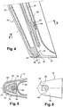
- the invention proposes that the ventilation box 24 be mounted and fixed inside the arm 10 independently of the thermal protection screen 28, as has been shown in FIGS. Figures 4 to 6 .
- the radially inner end of the ventilation box 24 comprises a cylindrical finger 40 which extends in the axis of the box 24 and which has an annular shoulder 42 forming a bearing surface on the edge of the orifice 44 formed in the base 32 of the arm 10, the cylindrical finger 40 extending outside this orifice and carrying an annular piece 46, such as a washer for example, which is fixed, for example by welding or brazing, on the end of the finger 40.
- the orifice 44 is formed in the bottom wall 48 of a small recess 49 of the base 32 of the arm 10, this bottom wall 48 being perpendicular to the axis of the box 24 and the finger 40.
- this recess 48 is not cylindrical in shape, as shown schematically in figure 6 the annular piece 46 can be given a corresponding shape so that this annular piece has a function of anti-rotation of the finger 40 and therefore of the box 24 around their longitudinal axis.
- One or two flats may also be formed in the contour of the annular piece 46, this flats or flats corresponding to planar faces of the recess 48 to give this anti-rotation function to the annular piece 46.
- the ventilation box 24 no longer includes the lug 36 engaged in an orifice of the heat shield 28 and the lug 34 shown in FIG. figure 1 is replaced by a transverse rim 50 of the box 24, this flange 50 being in the form of an angular sector and extending inside the body 20 of the arm 10 so as to occupy, in a transverse plane, the major part of the space available inside the arm 10 between the box 24 and the screen of thermal protection 28.
- the sides 52 and 54 of the flange 50 are approximately parallel to the side walls of the arm 10 and the screen 28 respectively, and extend a short distance from these walls, prohibiting a mounting of the radially internal end of the fuel rail 26 other than in the guide hole 56 formed in the flange 50. It thus greatly facilitates the blind assembly of the fuel rail 26 in the arm 10 and avoids any incorrect arrangement of the fuel rail, ensuring better cooling of the arm 10 by the fuel and extending the service life of the arm.
- the ventilation box 24 In case of burning of the thermal protection screen 28, the ventilation box 24 remains in the arm 10 and continues to perform its function of cooling the various elements of the arm.
- the fuel rail 26 is also held in place on the ventilation box 24 inside the arm and can not break.
Landscapes
- Engineering & Computer Science (AREA)
- Chemical & Material Sciences (AREA)
- Combustion & Propulsion (AREA)
- Mechanical Engineering (AREA)
- General Engineering & Computer Science (AREA)
- Structures Of Non-Positive Displacement Pumps (AREA)
- Heat-Exchange Devices With Radiators And Conduit Assemblies (AREA)
- Fuel-Injection Apparatus (AREA)
- Fireproofing Substances (AREA)
- Cylinder Crankcases Of Internal Combustion Engines (AREA)
Description
- La présente invention concerne un bras accroche-flammes d'une chambre de post-combustion dans une turbomachine telle qu'un turboréacteur.
- De façon classique, une chambre de post-combustion comprend une série de bras accroche-flammes qui sont formés chacun d'un dièdre creux dont l'arête de sommet est orientée vers l'amont de la chambre et qui est fermé du côté aval par un écran de protection thermique. Une rampe de carburant s'étend radialement à l'intérieur du bras depuis un carter externe de la chambre. Cette rampe est reliée à des moyens d'alimentation en carburant et comporte des trous de pulvérisation de carburant (voir par exemple les documents
EP-A-1 619 441 etFR-A-2 709 342 - Un caisson de ventilation s'étend dans le bras sensiblement parallèlement à la rampe, entre celle-ci et l'arête du dièdre du bras, et comporte à son extrémité radialement externe une ouverture de captation d'air de refroidissement destiné à être diffusé dans le bras à travers des trous du caisson. L'extrémité radialement interne du caisson de ventilation est fermée et comporte un doigt de centrage engagé dans un orifice du bras.
- Le caisson de ventilation comporte également, au voisinage de son extrémité radialement interne, un ergot en saillie vers l'aval et dont l'extrémité libre est engagée dans un orifice correspondant de l'écran de protection thermique pour assurer le maintien du caisson de ventilation. Un orifice formé dans l'ergot reçoit l'extrémité inférieure de la rampe de carburant pour la centrer dans le bras.
- Au montage, le bras est assemblé avec le caisson de ventilation et l'écran de protection thermique qui est fixé sur le bras au moyen de pions épaulés et soudés et qui immobilise le caisson de ventilation. Ensuite, la rampe de carburant est montée dans le bras depuis le carter externe de la chambre, par engagement de son extrémité radialement interne entre l'écran de protection thermique et le caisson de ventilation, jusqu'à ce que cette extrémité se loge dans l'orifice de centrage formé dans l'ergot du caisson.
- Cependant, cette opération est effectuée en aveugle, ce qui risque d'entraîner un mauvais montage de la rampe dont l'extrémité interne peut s'engager dans un espace libre situé entre l'ergot et une paroi latérale du bras. Il en résulte une mauvaise répartition du carburant pulvérisé dans le bras et une dégradation du refroidissement du bras, avec pour conséquence une possible destruction de l'écran de protection thermique.
- En fonctionnement, le caisson de ventilation est soumis à des vibrations importantes qui provoquent une usure par frottement de son ergot et de l'orifice correspondant de l'écran de protection thermique, ce qui se traduit par un déplacement du caisson vers l'intérieur, et par un dépassement du doigt du caisson dans le flux primaire, ainsi qu'une usure et un élargissement de l'orifice du bras qui reçoit le doigt de centrage du caisson.
- Le déplacement du caisson de ventilation vers l'intérieur peut entraîner le désengagement de la rampe de carburant de l'orifice de l'ergot et la rupture de la rampe.
-
- Est ainsi divulguée l'utilisation d'un bras accroche-flammes de chambre de post-combustion, ce bras comprenant un corps en forme de dièdre ouvert, un caisson de ventilation s'étendant à l'intérieur du corps et comportant à une extrémité un doigt de centrage engagé dans un orifice du corps, une rampe de carburant s'étendant à l'intérieur du corps le long du caisson de ventilation, des moyens de guidage et de centrage de la rampe par rapport au caisson, et un écran de protection thermique fixé sur le corps et fermant la face ouverte du dièdre, le caisson de ventilation comprenant des moyens d'immobilisation dans le corps du bras qui sont indépendants de l'écran de protection thermique.
- Ainsi, le centrage et l'immobilisation du caisson de ventilation dans le bras accroche-flammes sont assurés indépendamment de l'écran de protection thermique, ce qui permet de supprimer l'ergot de centrage et de fixation prévu sur le caisson dans la technique antérieure.
- Mais, le montage en aveugle de la rampe de carburant dans le corps du bras peut encore se traduire par une disposition incorrecte de cette rampe et provoquer une usure et une dégradation de la rampe de carburant et du corps du bras.
- Pour d'apporter une solution simple, efficace et économique à l'ensemble de ces problèmes, l'invention propose que le bras accroche-flammes d'une chambre de post-combustion, comprenant donc, comme précité, un corps en forme de dièdre ouvert, un caisson de ventilation s'étendant à l'intérieur du corps et comportant à une extrémité un doigt de centrage engagé dans un orifice du corps, une rampe de carburant s'étendant à l'intérieur du corps le long du caisson de ventilation, des moyens de guidage et de centrage de la rampe par rapport au caisson, et un écran de protection thermique fixé sur le corps et fermant la face ouverte du dièdre, le caisson de ventilation comprenant des moyens d'immobilisation dans le corps du bras, qui sont indépendants de l'écran de protection thermique, soit tel que le doigt de centrage comprend un épaulement annulaire destiné à venir en appui sur le bord de l'orifice du corps du bras, à l'intérieur du bras, que l'extrémité du doigt extérieure au bras comporte des moyens de retenue du doigt dans l'orifice, que les moyens de retenue comprennent une pièce annulaire fixée par brasage ou soudage sur le doigt du caisson, et que l'épaulement annulaire du doigt du caisson est appliqué sur le bras par la pièce annulaire fixée à l'extrémité de ce doigt.
- On assure ainsi une fixation sans jeu du caisson sur le corps du bras et on évite les vibrations radiales du caisson par rapport au corps du bras.
- On peut également prévoir que cette pièce annulaire comprenne au moins un méplat coopérant par butée avec un élément correspondant du corps du bras pour participer à l'immobilisation en rotation du caisson par rapport au bras.
- La présence du rebord transversal à l'intérieur du corps de bras empêche de monter l'extrémité de la rampe de carburant ailleurs que dans l'orifice de centrage formé dans ce rebord.
A noter que, grâce à la solution globale ci-avant, on a supprimé : - l'usure de l'écran de protection thermique qui résultait des vibrations de cet ergot dans l'orifice de réception formé dans l'écran,
- l'usure du doigt de centrage dans l'orifice formé dans le corps du bras et l'usure correspondante des bords de cet orifice,
- les risques de rupture de la rampe de carburant par désengagement des moyens de centrage et de guidage formés sur le caisson de ventilation.
- De préférence, le doigt de centrage du caisson traverse l'orifice formé dans le corps du bras et comporte lesdits moyens d'immobilisation du caisson sur le corps du bras.
- L'invention propose également un caisson de ventilation d'un bras accroche-flammes, comprenant une extrémité ouverte et une extrémité formée avec un doigt sensiblement axial, caractérisé en ce que ce doigt présente un épaulement annulaire d'appui sur un support.
- Ce caisson de ventilation est encore caractérisé en ce qu'il est formé avec un rebord transversal comportant un orifice traversant dont l'axe est sensiblement parallèle à l'axe longitudinal du caisson.
- L'invention concerne également une turbomachine, telle qu'un turboréacteur d'avion à chambre de post-combustion, caractérisée en ce qu'elle comprend au moins un bras accroche-flammes du type décrit dans ce qui précède.
- L'invention sera mieux comprise et d'autres détails, caractéristiques et avantages de la présente invention apparaîtront à la lecture de la description suivante faite à titre d'exemple non limitatif et en référence aux dessins annexés dans lesquels :
- la
figure 1 est une vue schématique partielle en coupe axiale d'une chambre de post-combustion d'une turbomachine ; - la
figure 2 est une vue à plus grande échelle d'une partie d'un bras accroche-flammes de lafigure 1 et illustre un dispositif de fixation d'un caisson de ventilation dans le bras accroche-flammes selon la technique antérieure ; - la
figure 3 est une vue en coupe selon la ligne III-III de lafigure 2 , à plus grande échelle ; - la
figure 4 est une vue correspondant à lafigure 2 mais illustre un dispositif de fixation selon l'invention ; - la
figure 5 est une vue en coupe selon la ligne V-V de lafigure 4 , à plus grande échelle. - la
figure 6 est une vue de dessous du bras de lafigure 4 . - On se réfère d'abord aux
figures 1 à 3 dans lesquelles un bras accroche-flammes 10 de la technique connue est monté sur un carter 12 d'une chambre de post-combustion d'un turboréacteur, à son extrémité radialement externe, ce bras 10 s'étendant de façon sensiblement radiale dans la chambre de post-combustion et traversant une tôle de confluence 14 qui sépare le flux primaire 16 des gaz chauds de combustion du flux secondaire 18 fourni par une soufflante montée à l'avant du turboréacteur. - De façon connue, le bras accroche-flammes 10 comprend un corps 20 en forme de dièdre ouvert, dont l'arête de sommet 22 est orientée vers l'amont et dont l'ouverture est tournée vers l'aval et dans lequel sont disposés un caisson de ventilation 24, une rampe de carburant 26 et un écran 28 de protection thermique ayant une section en C et qui ferme la face ouverte du corps 22.
- Le caisson de ventilation 24 s'étend à l'intérieur du bras le long de l'arête de sommet 22 et comprend une extrémité radialement externe qui est ouverte et est alimentée en air du flux secondaire 18 par une ouverture de la partie radialement externe du corps du bras. La partie radialement interne du caisson 24 comprend des perforations multiples de distribution de l'air à l'intérieur du bras.
- L'extrémité radialement interne du caisson forme un doigt cylindrique 30 qui est engagé sans jeu dans un orifice de la base 32 du corps du bras, l'extrémité du doigt 30 venant affleurer la face extérieure de cette base 32 sans faire saillie à l'extérieur du bras.
- Au voisinage de cette extrémité radialement externe, le caisson de ventilation 24 comporte une patte 34 qui s'étend vers l'aval en direction de l'écran 28 de protection thermique, de façon sensiblement perpendiculaire à l'axe longitudinal du caisson 24, et dont l'extrémité libre forme un ergot 36 engagé dans un orifice correspondant de l'écran 28.
- Cette patte 34 comporte également, dans une partie intermédiaire entre le caisson de ventilation 24 et l'ergot 36, un orifice traversant de réception de la partie inférieure de la rampe de carburant 26 pour le centrage de cette rampe à l'intérieur du bras 10.
- Au montage, le caisson de ventilation 24 est d'abord disposé dans le corps 20 du bras 10, puis l'écran de protection thermique 28 est mis en place, l'ergot 36 du caisson de ventilation étant engagé dans l'orifice de l'écran, puis l'écran 28 est fixé par soudure en quatre points 34 sur les parois latérales du corps 20 du bras, en fixant ainsi le caisson de ventilation 24 à l'intérieur du bras. La rampe de carburant 26 est ensuite montée en aveugle à l'intérieur du bras depuis l'extrémité radialement externe de celui-ci. Cette opération demande un soin particulier, car l'extrémité inférieure de la rampe de carburant 26 doit être engagée dans l'orifice prévu dans la patte 34 du caisson de ventilation 24 et non entre cette patte 34 et une paroi latérale du corps 20 du bras 10.
- En fonctionnement, le caisson de ventilation 24 est soumis à des vibrations radiales à l'intérieur du bras 10, ce qui se traduit par une usure de son ergot 36 et des bords de l'orifice correspondant de l'écran thermique 28 ainsi que par une usure du doigt 30 de son extrémité radialement interne et des bords de l'orifice correspondant formé dans la base 32 du bras 10.
- Ces usures se traduisent par une descente du caisson 24 à l'intérieur du bras 10, l'extrémité du doigt 30 venant faire saillie sous la base 32 du bras 10 et perturbant les conditions de la post-combustion. De plus, ce déplacement du caisson de ventilation 24 dans le bras 10 peut permettre à l'extrémité radialement interne de la rampe de carburant 26 de se dégager de son orifice de guidage formé dans la patte 34 du caisson de ventilation, ce qui provoque la rupture de la rampe de carburant 26.
- Pour éviter ces inconvénients, l'invention propose que le caisson de ventilation 24 soit monté et fixé à l'intérieur du bras 10 indépendamment de l'écran de protection thermique 28, comme cela a été représenté aux
figures 4 à 6 . - Dans ces figures, l'extrémité radialement interne du caisson de ventilation 24 comporte un doigt cylindrique 40 qui s'étend dans l'axe du caisson 24 et qui comporte un épaulement annulaire 42 formant une surface d'appui sur le bord de l'orifice 44 formé dans la base 32 du bras 10, le doigt cylindrique 40 s'étendant à l'extérieur de cet orifice et portant une pièce annulaire 46, telle qu'une rondelle par exemple, qui est fixée, par exemple par soudure ou brasure, sur l'extrémité du doigt 40.
- De façon avantageuse, l'orifice 44 est formé dans la paroi de fond 48 d'un petit renfoncement 49 de la base 32 du bras 10, cette paroi de fond 48 étant perpendiculaire à l'axe du caisson 24 et du doigt 40.
- Lorsque ce renfoncement 48 n'est pas de forme cylindrique, comme représenté schématiquement en
figure 6 , on peut donner à la pièce annulaire 46 une forme correspondante pour que cette pièce annulaire ait une fonction d'anti-rotation du doigt 40 et donc du caisson 24 autour de leur axe longitudinal. - On peut aussi pratiquer un ou deux méplats dans le contour de la pièce annulaire 46, ce ou ces méplats correspondant à des faces planes du renfoncement 48 pour donner cette fonction d'anti-rotation à la pièce annulaire 46.
- Comme on le voit bien sur les
figures 4 et 5 , le caisson de ventilation 24 ne comprend plus l'ergot 36 engagé dans un orifice de l'écran 28 de protection thermique et la patte 34 représentée enfigure 1 est remplacée par un rebord transversal 50 du caisson 24, ce rebord 50 étant en forme de secteur angulaire et s'étendant à l'intérieur du corps 20 du bras 10 de façon à occuper, dans un plan transversal, la majeure partie de l'espace disponible à l'intérieur du bras 10 entre le caisson 24 et l'écran de protection thermique 28. - Dans l'exemple représenté, les côtés 52 et 54 du rebord 50 sont à peu près parallèles aux parois latérales du bras 10 et de l'écran 28 respectivement, et s'étendent à faible distance de ces parois, en interdisant un montage de l'extrémité radialement interne de la rampe de carburant 26 ailleurs que dans l'orifice de guidage 56 formé dans le rebord 50. On facilite ainsi beaucoup le montage en aveugle de la rampe de carburant 26 dans le bras 10 et on évite toute disposition incorrecte de la rampe de carburant, en garantissant un meilleur refroidissement du bras 10 par le carburant et en prolongeant la durée de vie du bras.
- La fixation axiale sans jeu du doigt d'extrémité 40 du caisson 24 dans l'orifice 44 de la base 32 du bras 10 évite les vibrations radiales du caisson de ventilation 24 dans le bras et les usures résultantes du bras et du caisson.
- En cas de brûlure de l'écran de protection thermique 28, le caisson de ventilation 24 reste maintenu dans le bras 10 et continue d'assurer sa fonction de refroidissement des différents éléments du bras. La rampe de carburant 26 est également maintenue en place sur le caisson de ventilation 24 à l'intérieur du bras et ne peut se rompre.
Claims (9)
- Bras accroche-flammes d'une chambre de post-combustion, comprenant un corps (20) en forme de dièdre ouvert, un caisson de ventilation (24) s'étendant à l'intérieur du corps et comportant à une extrémité un doigt de centrage (40) engagé dans un orifice (44) du corps, une rampe de carburant (26) s'étendant à l'intérieur du corps le long du caisson de ventilation (24), des moyens de guidage et de centrage de la rampe (26) par rapport au caisson (24), et un écran de protection thermique (28) fixé sur le corps (20) et fermant la face ouverte du dièdre, le caisson de ventilation (24) comprenant des moyens (46) d'immobilisation dans le corps du bras, qui sont indépendants de l'écran de protection thermique, ledit bras étant caractérisé en ce que le doigt de centrage (40) comprend un épaulement annulaire (42) destiné à venir en appui sur le bord de l'orifice (44) du corps du bras, à l'intérieur du bras, en ce que l'extrémité du doigt (40) extérieure au bras comporte des moyens (46) de retenue du doigt dans l'orifice, en ce que les moyens de retenue comprennent une pièce annulaire (46) fixée par brasage ou soudage sur le doigt du caisson, et en ce que l'épaulement annulaire (42) du doigt du caisson est appliqué sur le bras par la pièce annulaire (46) fixée à l'extrémité de ce doigt.
- Bras selon la revendication 1, caractérisé en ce que le doigt (40) de centrage du caisson de ventilation traverse l'orifice (44) du corps et comporte les moyens (46) d'immobilisation du caisson sur le corps du bras.
- Bras selon la revendication 1 ou 2, caractérisé en ce que la pièce annulaire (46) comprend au moins un méplat coopérant par butée avec un élément correspondant du bras pour s'opposer à la rotation du doigt dans l'orifice.
- Bras selon l'une des revendications précédentes, caractérisé en ce que le caisson de ventilation (24) comprend un rebord transversal (50) comportant un orifice (56) de centrage de la rampe de carburant (26).
- Bras selon la revendication 4, caractérisé en ce que le rebord transversal (50) du caisson occupe la quasi-totalité de l'espace disponible à l'intérieur du bras (10) pour empêcher un mauvais montage de la rampe de carburant (26).
- Bras selon la revendication 4 ou 5, caractérisé en ce que le caisson de ventilation (24) est formé d'une seule pièce avec le doigt (40) et le rebord transversal (50).
- Caisson de ventilation d'un bras accroche-flammes, comprenant une extrémité ouverte et une extrémité opposée formée avec un doigt sensiblement axial (40), caractérisé en ce que ce doigt présente un épaulement annulaire (42) d'appui sur un support.
- Caisson de ventilation selon la revendication 7, caractérisé en ce qu'il est formé avec un rebord transversal (50) comportant un orifice traversant (56) dont l'axe est sensiblement parallèle à l'axe du caisson.
- Turbomachine à chambre de post-combustion, caractérisée en ce qu'elle comprend au moins un bras accroche-flammes (10) selon l'une des revendications 1 à 6.
Applications Claiming Priority (1)
| Application Number | Priority Date | Filing Date | Title |
|---|---|---|---|
| FR0602742A FR2899316B1 (fr) | 2006-03-30 | 2006-03-30 | Bras accroche-flammes d'une chambre de post-combustion |
Publications (2)
| Publication Number | Publication Date |
|---|---|
| EP1840469A1 EP1840469A1 (fr) | 2007-10-03 |
| EP1840469B1 true EP1840469B1 (fr) | 2018-12-05 |
Family
ID=37199105
Family Applications (1)
| Application Number | Title | Priority Date | Filing Date |
|---|---|---|---|
| EP07290288.5A Active EP1840469B1 (fr) | 2006-03-30 | 2007-03-06 | Bras accroche-flammes d'une chambre de post-combustion |
Country Status (5)
| Country | Link |
|---|---|
| US (1) | US7856828B2 (fr) |
| EP (1) | EP1840469B1 (fr) |
| CA (1) | CA2582624C (fr) |
| FR (1) | FR2899316B1 (fr) |
| RU (1) | RU2410604C2 (fr) |
Families Citing this family (8)
| Publication number | Priority date | Publication date | Assignee | Title |
|---|---|---|---|---|
| FR2873408B1 (fr) * | 2004-07-23 | 2008-10-17 | Snecma Moteurs Sa | Turboreacteur avec un ecran de protection de la rampe de carburant d'un anneau bruleur, l'anneau bruleur et l'ecran de protection |
| FR2928202A1 (fr) * | 2008-02-29 | 2009-09-04 | Snecma Sa | Accroche flamme pour canal de rechauffe d'un turboreacteur avec une semelle d'ecartement, canal de rechauffe et turboreacteur comprenant un canal de rechauffe. |
| FR2950416B1 (fr) * | 2009-09-23 | 2012-04-20 | Snecma | Dispositif accroche-flammes comprenant un support de bras et un ecran de protection thermique monoblocs |
| CN109352287B (zh) * | 2018-12-06 | 2020-10-13 | 中国航发贵州黎阳航空动力有限公司 | 一种钣焊结构件精密孔的加工方法 |
| FR3097298B1 (fr) | 2019-06-12 | 2021-06-04 | Safran Aircraft Engines | Bougie intégrée au bras accroche-flamme |
| CN113701191B (zh) * | 2021-09-01 | 2022-06-24 | 南昌航空大学 | 一种交错导流中缝式v型火焰稳定器 |
| GB2615335B (en) * | 2022-02-04 | 2024-05-08 | Rolls Royce Plc | A reheat assembly |
| GB2643904A (en) * | 2024-09-06 | 2026-03-11 | Rolls Royce Plc | Reheat assembly for a gas turbine engine |
Citations (1)
| Publication number | Priority date | Publication date | Assignee | Title |
|---|---|---|---|---|
| EP1593911A1 (fr) * | 2004-05-05 | 2005-11-09 | Snecma | Dispositif d'alimentation en air et en carburant d'un anneau-brûleur dans une chambre de postcombustion |
Family Cites Families (8)
| Publication number | Priority date | Publication date | Assignee | Title |
|---|---|---|---|---|
| US3698186A (en) * | 1970-12-24 | 1972-10-17 | United Aircraft Corp | Afterburner combustion apparatus |
| FR2221621B1 (fr) * | 1973-03-13 | 1976-09-10 | Snecma | |
| FR2709342B1 (fr) * | 1993-08-25 | 1995-09-22 | Snecma | Dispositif de post combustion d'un turboréacteur. |
| RU2069792C1 (ru) * | 1994-02-11 | 1996-11-27 | Акционерное общество открытого типа "Ленинградский Металлический завод" | Шарнирный узел механизма поворота лопастей гидромашины |
| US5396761A (en) * | 1994-04-25 | 1995-03-14 | General Electric Company | Gas turbine engine ignition flameholder with internal impingement cooling |
| US6971239B2 (en) * | 2003-05-13 | 2005-12-06 | United Technologies Corporation | Augmentor pilot nozzle |
| FR2869875B1 (fr) * | 2004-05-05 | 2006-06-16 | Snecma Moteurs Sa | Dispositif de fixation d'un conduit de fluide sur un carter d'un turboreacteur |
| FR2873411B1 (fr) * | 2004-07-21 | 2009-08-21 | Snecma Moteurs Sa | Turboreacteur avec des moyens de protection pour un dispositif d'injection de carburant, dispositif d'injection et tole de protection pour le turboreacteur |
-
2006
- 2006-03-30 FR FR0602742A patent/FR2899316B1/fr not_active Expired - Lifetime
-
2007
- 2007-03-06 EP EP07290288.5A patent/EP1840469B1/fr active Active
- 2007-03-28 CA CA2582624A patent/CA2582624C/fr active Active
- 2007-03-29 US US11/693,177 patent/US7856828B2/en active Active
- 2007-03-29 RU RU2007111676/06A patent/RU2410604C2/ru active
Patent Citations (1)
| Publication number | Priority date | Publication date | Assignee | Title |
|---|---|---|---|---|
| EP1593911A1 (fr) * | 2004-05-05 | 2005-11-09 | Snecma | Dispositif d'alimentation en air et en carburant d'un anneau-brûleur dans une chambre de postcombustion |
Also Published As
| Publication number | Publication date |
|---|---|
| US7856828B2 (en) | 2010-12-28 |
| RU2410604C2 (ru) | 2011-01-27 |
| FR2899316B1 (fr) | 2008-05-16 |
| RU2007111676A (ru) | 2008-10-10 |
| US20070227151A1 (en) | 2007-10-04 |
| CA2582624A1 (fr) | 2007-09-30 |
| CA2582624C (fr) | 2015-01-13 |
| EP1840469A1 (fr) | 2007-10-03 |
| FR2899316A1 (fr) | 2007-10-05 |
Similar Documents
| Publication | Publication Date | Title |
|---|---|---|
| CA2582624C (fr) | Bras accroche-flammes d'une chambre de post-combustion | |
| EP3833861B1 (fr) | Cone d'éjection à fixation flexible | |
| EP2334909B1 (fr) | Etanchéité entre une chambre de combustion et un distributeur de turbine dans une turbomachine | |
| EP2071242B1 (fr) | Système d'injection d'un mélange d'air et de carburant dans une chambre de combustion de turbomachine | |
| EP1840364B1 (fr) | Chambre de post-combustion | |
| EP1811131B1 (fr) | Ensemble de redresseurs fixes sectorise pour un compresseur de turbomachine | |
| EP3591178B1 (fr) | Module d'étanchéité de turbomachine | |
| EP2031188B1 (fr) | Etage d'aubes à calage variable pour une turbomachine | |
| EP3247946B1 (fr) | Agencement pour une chambre de combustion de turbomachine d'aéronef | |
| EP4025780B1 (fr) | Cone d'ejection a fixation flexible aerodynamique | |
| CA2956882C (fr) | Module de turbomachine | |
| EP3736413B1 (fr) | Module de turbomachine équipé d'un dispositif de maintien de lamelles d' étanchéité | |
| EP1849986A1 (fr) | Turboréacteur comprenant un canal de post combustion refroidi par un flux de ventilation a débit variable | |
| EP1939528B1 (fr) | Déflecteur pour fond de chambre de combustion, chambre de combustion en étant équipée et turboréacteur les comportant | |
| EP3201531B1 (fr) | Chambre de combustion de turbomachine | |
| EP3551859A1 (fr) | Dispositif de récupération de chaleur à l'échappement, à étanchéité améliorée | |
| WO2012022873A2 (fr) | Systeme d'injection de carburant pour turbo-reacteur et procede d'assemblage d'un tel systeme d'injection | |
| EP3969813B1 (fr) | Chambre de combustion comprenant des moyens de refroidissement d'une zone d'enveloppe annulaire en aval d'une cheminée | |
| FR3055950B1 (fr) | Chambre de combustion pour turbomachine comprenant des moyens pour ameliorer le refroidissement d'une paroi annulaire dans le sillage d'un obstacle | |
| FR2952704A1 (fr) | Guidage rotulant d'une bougie d'allumage dans une chambre de combustion d'une turbomachine | |
| EP4136386A1 (fr) | Bougie pour chambre de combustion monobloc | |
| EP3359423B1 (fr) | Ensemble pour châssis de vehicule automobile | |
| FR3088412A1 (fr) | Chambre de combustion de turbomachine, turbomachine associee | |
| FR2952702A1 (fr) | Guidage d'une bougie d'allumage dans une chambre de combustion | |
| FR3070058A1 (fr) | Turbomachine pour aeronef comprenant un element de refroidissement ameliorant le refroidissement par convection et offrant un refroidissement par impact de jet d'air d'une bride de liaison terminale de paroi de chambre annulaire de combustion |
Legal Events
| Date | Code | Title | Description |
|---|---|---|---|
| PUAI | Public reference made under article 153(3) epc to a published international application that has entered the european phase |
Free format text: ORIGINAL CODE: 0009012 |
|
| AK | Designated contracting states |
Kind code of ref document: A1 Designated state(s): AT BE BG CH CY CZ DE DK EE ES FI FR GB GR HU IE IS IT LI LT LU LV MC MT NL PL PT RO SE SI SK TR |
|
| AX | Request for extension of the european patent |
Extension state: AL BA HR MK YU |
|
| 17P | Request for examination filed |
Effective date: 20071124 |
|
| AKX | Designation fees paid |
Designated state(s): DE FR GB SE |
|
| STAA | Information on the status of an ep patent application or granted ep patent |
Free format text: STATUS: EXAMINATION IS IN PROGRESS |
|
| 17Q | First examination report despatched |
Effective date: 20170320 |
|
| GRAP | Despatch of communication of intention to grant a patent |
Free format text: ORIGINAL CODE: EPIDOSNIGR1 |
|
| STAA | Information on the status of an ep patent application or granted ep patent |
Free format text: STATUS: GRANT OF PATENT IS INTENDED |
|
| INTG | Intention to grant announced |
Effective date: 20180601 |
|
| RAP1 | Party data changed (applicant data changed or rights of an application transferred) |
Owner name: SAFRAN AIRCRAFT ENGINES |
|
| GRAS | Grant fee paid |
Free format text: ORIGINAL CODE: EPIDOSNIGR3 |
|
| GRAJ | Information related to disapproval of communication of intention to grant by the applicant or resumption of examination proceedings by the epo deleted |
Free format text: ORIGINAL CODE: EPIDOSDIGR1 |
|
| GRAL | Information related to payment of fee for publishing/printing deleted |
Free format text: ORIGINAL CODE: EPIDOSDIGR3 |
|
| STAA | Information on the status of an ep patent application or granted ep patent |
Free format text: STATUS: EXAMINATION IS IN PROGRESS |
|
| GRAR | Information related to intention to grant a patent recorded |
Free format text: ORIGINAL CODE: EPIDOSNIGR71 |
|
| STAA | Information on the status of an ep patent application or granted ep patent |
Free format text: STATUS: GRANT OF PATENT IS INTENDED |
|
| GRAA | (expected) grant |
Free format text: ORIGINAL CODE: 0009210 |
|
| INTC | Intention to grant announced (deleted) | ||
| GRAA | (expected) grant |
Free format text: ORIGINAL CODE: 0009210 |
|
| STAA | Information on the status of an ep patent application or granted ep patent |
Free format text: STATUS: THE PATENT HAS BEEN GRANTED |
|
| AK | Designated contracting states |
Kind code of ref document: B1 Designated state(s): DE FR GB SE |
|
| INTG | Intention to grant announced |
Effective date: 20181026 |
|
| REG | Reference to a national code |
Ref country code: GB Ref legal event code: FG4D Free format text: NOT ENGLISH |
|
| REG | Reference to a national code |
Ref country code: DE Ref legal event code: R096 Ref document number: 602007057023 Country of ref document: DE |
|
| REG | Reference to a national code |
Ref country code: SE Ref legal event code: TRGR |
|
| REG | Reference to a national code |
Ref country code: DE Ref legal event code: R097 Ref document number: 602007057023 Country of ref document: DE |
|
| PLBE | No opposition filed within time limit |
Free format text: ORIGINAL CODE: 0009261 |
|
| STAA | Information on the status of an ep patent application or granted ep patent |
Free format text: STATUS: NO OPPOSITION FILED WITHIN TIME LIMIT |
|
| 26N | No opposition filed |
Effective date: 20190906 |
|
| PGFP | Annual fee paid to national office [announced via postgrant information from national office to epo] |
Ref country code: SE Payment date: 20260323 Year of fee payment: 20 |
|
| PGFP | Annual fee paid to national office [announced via postgrant information from national office to epo] |
Ref country code: GB Payment date: 20260324 Year of fee payment: 20 |
|
| PGFP | Annual fee paid to national office [announced via postgrant information from national office to epo] |
Ref country code: DE Payment date: 20260320 Year of fee payment: 20 |
|
| PGFP | Annual fee paid to national office [announced via postgrant information from national office to epo] |
Ref country code: FR Payment date: 20260324 Year of fee payment: 20 |