EP1840471A2 - Dispositif pour attacher a brûleur à fonctionnement séquentiel dans une turbine à gaz - Google Patents
Dispositif pour attacher a brûleur à fonctionnement séquentiel dans une turbine à gaz Download PDFInfo
- Publication number
- EP1840471A2 EP1840471A2 EP07103514A EP07103514A EP1840471A2 EP 1840471 A2 EP1840471 A2 EP 1840471A2 EP 07103514 A EP07103514 A EP 07103514A EP 07103514 A EP07103514 A EP 07103514A EP 1840471 A2 EP1840471 A2 EP 1840471A2
- Authority
- EP
- European Patent Office
- Prior art keywords
- flow channel
- burner
- opening
- channel wall
- sev
- Prior art date
- Legal status (The legal status is an assumption and is not a legal conclusion. Google has not performed a legal analysis and makes no representation as to the accuracy of the status listed.)
- Granted
Links
Images


Classifications
-
- F—MECHANICAL ENGINEERING; LIGHTING; HEATING; WEAPONS; BLASTING
- F23—COMBUSTION APPARATUS; COMBUSTION PROCESSES
- F23R—GENERATING COMBUSTION PRODUCTS OF HIGH PRESSURE OR HIGH VELOCITY, e.g. GAS-TURBINE COMBUSTION CHAMBERS
- F23R3/00—Continuous combustion chambers using liquid or gaseous fuel
- F23R3/28—Continuous combustion chambers using liquid or gaseous fuel characterised by the fuel supply
- F23R3/283—Attaching or cooling of fuel injecting means including supports for fuel injectors, stems, or lances
Definitions
- the invention relates to a device for fastening a second burner, in short SEV burner, in a sequentially operated gas turbine arrangement in which a fuel / air mixture is burned in a first burner to form hot gases, which subsequently partially expanded the SEV Burners are supplied for a second combustion, which is formed substantially as a flow channel, with a flow channel wall having an opening through which a fuel supply to the interior of the SEV burner is insertable, and on the in the axial direction of the opening in each case two opposite Fastening structures are provided, in each of which a support structure for further attachment of the SEV burner to an outer support can be inserted.
- a gas turbine arrangement with a sequential combustion is, for example, from the EP 0 620 362 B1 forth, in which along a single rotor shaft in the direction of flow of the gas turbine assembly of an air compressor unit is arranged a circularly arranged around the rotor shaft annular combustion chamber, which is fed by a plurality annularly distributed premix burner with an ignitable fuel-air mixture, which is brought to the ignition, from which hot gases driving a first turbine stage provided downstream of the annular combustor and connected to the rotor shaft.
- the partially expelled from the first turbine stage hot gases then go into one annular flow channel, in which the partially expanded hot gases are mixed again with fuel and are brought to form a sezündGermanen hot gas fuel mixture within a second circular or the rotor shaft annularly surrounding second annular combustion chamber for ignition.
- the resulting hot gases go downstream in a second, a so-called. Low-pressure turbine stage, to make further expansion work.
- the second or sequential burner designed as a flow channel which is referred to below as an SEV burner, should be considered in more detail, in particular with regard to the attachment of the flow channel within the gas turbine plant and its thermal and mechanical properties.
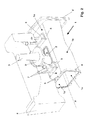
- An SEV burner 1 which is known per se as a flow channel is evident from the image representation according to FIG. 2, which has a rectangular flow channel cross section in the embodiment shown and is bounded by four flow channel walls, an upper 1o, lower 1u and two lateral flow channel walls 1s.
- an opening 2 is introduced, through which a fuel lance 3 serves for fuel enrichment of the part-expanded hot gases entering the SEV burner.
- this is inserted through the opening 2 of the flow channel 1 from above, the lance tip 3 terminates with a defined game to the upper flow channel wall 1o and is positioned.
- the game to be provided between the lance tip and the upper flow channel wall should allow the simplest possible assembly of the lance tip, yet cause the smallest possible leakage between the components.
- the SEV burner 1 has upstream of its flow channel to a mounting flange 4, which is connected to a not shown further expansion stage of the gas turbine plant, ie, a first turbine stage.
- the SEV burner is connected at least one side axially fixed to the gas turbine.
- each two screw or pin-like fastening means 7 are provided which fix the support structures 6 each with a SEV burner 1 towering outer support 8 of the gas turbine assembly.
- the fuel lance 3 likewise extends through the outer support 8, a support ring 3 'with integrated piston ring serving to ensure a seal between the radially inner region and the outer support 8, in particular in the case of thermally induced changes in shape especially when starting but also during operation of the gas turbine arrangement occur.
- the fuel lances tip is displaced by the burner in the flow direction or elastically bent, so that on the one hand a required minimum clearance between the outer carrier and the fuel lance tip must be provided, on the other hand, it is to avoid leakage currents, this game with a not From Figure 2 apparent seal piston ring.
- the mounting flange 4 opposite flange 4 'of the flow channel 1 via, provided on the upper side channel wall 1o fixing lugs 9 is directly connected to the outer support 8, so that the SEV burner 1 is axially locked. In the circumferential direction, however, the SEV burner 1 is fixed by the two support structures 6 and the associated fastening means 7 relative to the outer support 8.
- the invention is based on the object, a device for fastening a second burner, short SEV burner, in a sequentially operated gas turbine arrangement in which a fuel-air mixture is burned in a first burner to form hot gases, which subsequently partially expanded the SEV burner be supplied for a second combustion, which is formed substantially as a flow channel having a flow channel wall having an opening through which a fuel supply into the interior of the SEV burner is insertable, and provided on the opposite in the axial direction of the opening in each case two attachment structures are, in each of which a support structure for further attachment of the SEV burner to an outer support can be introduced in such a way that operational and structural, in particular occurring at the location of the opening between the SEV burner and the fuel lance vibrations should be avoided.
- a device is formed in that the support structure is formed as a unitary support plate, are provided on the mating contours for attachment to the two, the opening opposite mounting structures and which provides a recess, the least of the size corresponds to the opening in the flow channel wall, so that the support plate in the attached state on the outer support does not cover the opening of the flow channel wall.
- the idea underlying the invention provides for the substitution of the two separately formed support structures which are axially insertable into the two separately axially spaced receiving rails by a uniform, continuous support plate, which also in the provided on the sokanalwandoberseite attachment structures or receiving rails axially inserted.
- a particularly advantageous embodiment also provides that in the region of the opening additional connecting means between the opening edge and the support plate are provided through which an additional radial support between the opening edge and the support plate is possible.
- at least one collar preferably two at the opening edge diametrically opposite arranged collar provided at the opening, which project vertically beyond the flow channel wall and each having a mounting lip which is insertable into a provided on the support plate groove-shaped recess.
- the at least one plate element mounted on the lower flow channel wall via spacer means, on the one hand the at least one plate element at least partially spaced from the lower flow channel wall and on the other hand is slidably attached to this.
- the one hand ensures that due to the spaced attachment of the plate member to the lower flow channel wall, this can be cooled by means of a conventional so-called.
- Effusionskühlung on the other hand, however, a direct cherriesstrahlungsbeaufschlagung the lower flow channel wall opposite system components avoided by the plate member.
- the plate member while being slidably mounted relative to the lower flow channel wall, contributes to some extent to an increase in rigidity of the at least lower flow channel wall, particularly since it is not connected to a support member as stated above for the upper flow channel wall.
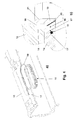
- FIG. 1a a perspective view of a SEV burner 1 is shown, the upper flow channel wall 10 can be seen on which the known per se, designed as receiving rails 5 mounting structures are provided, in the axial direction of the SEV burner 1 as a one-piece component manufactured Support plate 10, which in turn has corresponding lateral effetsnut Modellen 11, is inserted.
- the support plate 10 has an opening (FIG. 1b) which, in the case of the exemplary embodiment according to FIG. 1a, surrounds the opening 2 inside the upper flow passage wall 1 o in a frame-like manner, without even partially covering it, so as to ensure that it is not in Figure 1a illustrated burner lance unhindered through the opening 2 can be mounted in the SEV burner 1.
- the support plate 10 can be mounted by mere axial displacement relative to the support structures formed as a mounting rails 5 and the collar 12, it requires the axial fixing of the support plate 10 an additional attachment via the fastening means 7 on the outer support 8 as it were previously in the state of Technique usual practice.
- the formation of the collar 12 can on the one hand be made in one piece from the same material from which the at least upper flow channel wall 10 is formed, alternatively it is also possible, the collar 12 in the form of an additional, modular insert from below into the opening 2 of the SEV burner, as the embodiment below with reference to Figure 3 shows.
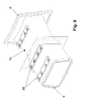
- FIG. 3a the assembled state of a support plate 10 is shown relative to the SEV burner 1, wherein the burner lance 3 is shown in the mounted state and extends through both the support plate 10 and provided in the SEV burner opening 2.
- a modularly designed insert element 15 is provided, which is inserted from the inside of the flow channel into the opening of the SEV burner and the upper flow channel wall 1 o towered vertically.
- the insert element 15 For fluid-tight closure between the module-shaped insert element 15 and the flow channel wall, the insert element 15 has a lower circumferential support web 16 which is flush and fit into a receiving contour 17 along the peripheral edge of the opening 2 can be used.
- collar-like sections 18 are provided which can be inserted into corresponding receiving grooves provided in the carrier plate 10.
- the support plate 10 undergoes a radial connection to the insert element 15 and is thus centered and fixed relative to the SEV burner. Due to the axially symmetrical design of both the support plate 10 and the insert element 15, it is possible, depending on the existing mounting space, the support plate 10 to be mounted on both sides to the axial direction for purposes of introduction.
- additional sealing materials 19, or sealing means As can be seen from the detailed image representation according to FIG. 3 c.
- the insert element 15 Due to the separate formation of the insert element 15 thus a handy component is created, the entire surface or at least the contact surfaces can be provided to the SEV burner and the fuel lance with a wear-resistant surface layer. This allows the hitherto complex surface protection, by way of a plasma treatment especially on the so-called. Balcony of the fuel lance is to be saved. Should there still be wear on the contact surface between the fuel lance and the insert element, on which the fuel lance centered and flush, so it only requires the replacement and replacement of the otherwise inexpensive producible insert element 15th
- the easy mounting of the insert element 15 from below in the direction of the opening 2 of the SEV burner can be seen.
- a sealing means 19, which runs along the receiving contour 17 at the opening 2 are provided in order to provide a fluid-tight seal of the inner flow channel with respect to the use of the burner lance to be carried out hereinafter.
- a further fixation of the insert element 15 relative to the SEV burner is not required, especially as a result of axial displacement of the carrier plate 10 and the engagement between the collar-like sections 18 with the groove-shaped recesses 14 of the carrier plate 10 a mutual firm joining between the carrier plate 10 and insert member 15 made can be. This is also evident from the partial cross-sectional view according to FIG.
- the insert member 15 is flush with its support web 16 partially overlapping with the receiving contour 17 at the opening edge of the upper flow channel wall 10.
- the receiving contour 17 further provides a groove-shaped recess 17 'into which the sealing means 19 is introduced.
- the insert member 15 vertically, the upper flow channel wall 10 protruding a collar-like portion 18 which opens into a groove-shaped recess 14 of the support plate 10 and is pressed by this vertically upwards against the receiving contour 17.
- the insert element 15 provides for its cooling so-called effusion holes 20, which open at the surface which faces the hot gases within the flow channel.
- the partial cross-sectional view according to FIG. 4 b can be seen that the insert element 15 has an obliquely inclined with respect to the vertical and the opening 2 facing the introduction edge 21, the better and simplified centering and mounting of the fuel lance in the SEV burner 1 allows.
- FIG. 5 a shows a further alternative embodiment with regard to the carrier plate 10.
- Figure 5a shows a partial longitudinal section through the opening portion 2 of the upper flow channel wall 1o, wherein in the right portion of the partial longitudinal sectional view, a part of the mounting flange 4 is shown, which is connected flush with a first turbine stage region provided upstream.
- the support plate 10 has an axial, in the direction of the mounting flange 4 oriented extension 10 ', with which the support plate 10 abuts in the axial direction of the region of the mounting flange 4 and thus undergoes an axial locking.
- the mounting of the carrier plate 10 relative to the SEV burner takes place counter to the flow direction with which the hot gases entering the SEV burner from the turbine stage flow through the SEV burner.
- FIG. 5b shows a representation in the axial direction of view opposite to the flow direction of the flow channel of the SEV burner. It can be seen that at the burner flange 4 additional fastening hooks 22 are provided, on which the carrier plate 10 are axially and radially fixed, whereby the outer diameter of the burner inlet is defined radially relative to the gas turbine outlet not shown. This prevents lowering of the SEV burner inlet from the upstream first turbine stage due to creep. Furthermore, the SEV burner is further fixed against axial displacement relative to the outer support 8 (not shown) via corresponding fastening means 7 on the support plate 10.
- the lower flow channel wall 1 u is supported in contrast to the upper only by the two burner flanges 4 and 4 'and the flow channel side walls 1s (see, for example, the illustration of the figures according to FIG. 2).
- the lower flow channel wall 1 u not connected to a support member provided for the upper flow channel wall.
- the inherent rigidity of the lower flow channel wall 1 u is therefore provided exclusively by the flanges 4 and 4 'and optionally by an additional rib. It is obvious that due to thermal stresses and compressive forces, deformations along the lower flow channel wall 1u may occur.
- FIG. 6a shows the bottom flow channel wall 1 u of the SEV burner 1 in plan view. So it is assumed that the SEV burner 1 is connected via the mounting flange 4 with a not shown first turbine stage.
- the plate member 22 is connected along its planar axial extent via individual linearly arranged spacer means with the lower flow channel wall 1 u, wherein from the detailed illustration according to Figure 6c of the exact fastening mechanism can be seen.
- a so-called mounting pin 23 is provided directly with the lower flow channel wall 1 u each at the location of a sliding attachment, which provides a mushroom-shaped portion 23 'on which the plate member 22 slidably abuts.
- the plate member 22 is about a kind Clip connection 24 against the mushroom-shaped portion 23 'slidably pressed. This applies to all fastening points of the plate element 22 with respect to the lower flow channel wall 1 u, as can be seen, for example. From a cross-sectional view of Figure 6b. The distance between the plate member 22 and the lower flow channel wall 1u is selected so that effusion cooling of the SEV burner is not affected. Different thermal expansions of the SEV burner and the plate element 22 can be absorbed or compensated due to the sliding suspension as described above. To increase the surface rigidity of the plate element 22, the surface element 22 provides local profile displacements 25 (FIG. 6a), along which the sliding attachment points are mounted.
- FIG. 7 shows a further exemplary embodiment for the formation and attachment of a plate element 22 on the lower flow channel wall 1 u. 7 shows a longitudinal section through the one SEV burner 1 and the radially inner inner support 26. In this case, the plate element 22 projects beyond the region of the SEV burner up to the burner flange 4, wherein the burner or inlet flange 4 is offset, over which the plate member 22 is suitably guided and is fixed with this via hooks.
- the flat plate member 22 is formed exclusively reduced to the areas of Profilabsenkonne 25, although weight can be reduced, however, this variant can not protect the radially inner inner support from the direct heat radiation of the SEV burner 1. Rather, the rigidity of the sheets is increased by the U-shape of the Profilabsenkonne 25 and thus the rigidity of the lower flow channel wall 1 u.
- This embodiment represents only an alternative to the usual wall stiffening by means of profiles.
Landscapes
- Engineering & Computer Science (AREA)
- Chemical & Material Sciences (AREA)
- Combustion & Propulsion (AREA)
- Mechanical Engineering (AREA)
- General Engineering & Computer Science (AREA)
- Gas Burners (AREA)
Priority Applications (1)
| Application Number | Priority Date | Filing Date | Title |
|---|---|---|---|
| EP09155057.4A EP2077421B1 (fr) | 2006-03-31 | 2007-03-05 | Dispositif pour attacher un brûleur à fonctionnement séquentiel dans une turbine à gaz |
Applications Claiming Priority (1)
| Application Number | Priority Date | Filing Date | Title |
|---|---|---|---|
| DE102006015093 | 2006-03-31 |
Related Child Applications (2)
| Application Number | Title | Priority Date | Filing Date |
|---|---|---|---|
| EP09155057.4A Division EP2077421B1 (fr) | 2006-03-31 | 2007-03-05 | Dispositif pour attacher un brûleur à fonctionnement séquentiel dans une turbine à gaz |
| EP09155057.4 Division-Into | 2009-03-12 |
Publications (3)
| Publication Number | Publication Date |
|---|---|
| EP1840471A2 true EP1840471A2 (fr) | 2007-10-03 |
| EP1840471A3 EP1840471A3 (fr) | 2008-02-20 |
| EP1840471B1 EP1840471B1 (fr) | 2011-07-27 |
Family
ID=38292665
Family Applications (2)
| Application Number | Title | Priority Date | Filing Date |
|---|---|---|---|
| EP07103514A Not-in-force EP1840471B1 (fr) | 2006-03-31 | 2007-03-05 | Dispositif pour attacher un brûleur à fonctionnement séquentiel dans une turbine à gaz |
| EP09155057.4A Not-in-force EP2077421B1 (fr) | 2006-03-31 | 2007-03-05 | Dispositif pour attacher un brûleur à fonctionnement séquentiel dans une turbine à gaz |
Family Applications After (1)
| Application Number | Title | Priority Date | Filing Date |
|---|---|---|---|
| EP09155057.4A Not-in-force EP2077421B1 (fr) | 2006-03-31 | 2007-03-05 | Dispositif pour attacher un brûleur à fonctionnement séquentiel dans une turbine à gaz |
Country Status (4)
| Country | Link |
|---|---|
| US (1) | US7937950B2 (fr) |
| EP (2) | EP1840471B1 (fr) |
| AT (1) | ATE518101T1 (fr) |
| ES (2) | ES2369524T3 (fr) |
Families Citing this family (3)
| Publication number | Priority date | Publication date | Assignee | Title |
|---|---|---|---|---|
| EP2116768B1 (fr) * | 2008-05-09 | 2016-07-27 | Alstom Technology Ltd | Brûleur |
| EP3029378B1 (fr) * | 2014-12-04 | 2019-08-28 | Ansaldo Energia Switzerland AG | Brûleur séquentiel pour une turbine à gaz axiale |
| EP3296638B1 (fr) | 2016-09-20 | 2020-02-19 | General Electric Technology GmbH | Brûleur complet et procédé pour brûleur d'une turbine à gaz |
Citations (4)
| Publication number | Priority date | Publication date | Assignee | Title |
|---|---|---|---|---|
| US3147594A (en) | 1962-03-19 | 1964-09-08 | Continental Aviat & Eng Corp | Fuel injection device |
| EP0550126A1 (fr) | 1992-01-02 | 1993-07-07 | General Electric Company | Bouclier thermique pour post-combusteur |
| EP0616111A1 (fr) | 1993-03-11 | 1994-09-21 | ROLLS-ROYCE plc | Support pour l'extrémité aval d'une chambre de combustion d'une turbine à gaz |
| EP0620362B1 (fr) | 1993-04-08 | 1999-02-10 | Asea Brown Boveri Ag | Turbine à gaz |
Family Cites Families (7)
| Publication number | Priority date | Publication date | Assignee | Title |
|---|---|---|---|---|
| US3565968A (en) | 1967-07-31 | 1971-02-23 | Ashland Oil Inc | Cracking and recovery of hydrocarbons |
| FR2646880A1 (fr) | 1989-05-11 | 1990-11-16 | Snecma | Chemise de protection thermique pour canal de post-combustion ou de transition d'un turboreacteur |
| JPH0772616B2 (ja) | 1989-05-24 | 1995-08-02 | 株式会社日立製作所 | 燃焼器及びその運転方法 |
| DE4223733C2 (de) * | 1992-07-18 | 1995-05-18 | Gutehoffnungshuette Man | Verbindung von Mischrohr und Flammrohr einer Gasturbine |
| US6339923B1 (en) * | 1998-10-09 | 2002-01-22 | General Electric Company | Fuel air mixer for a radial dome in a gas turbine engine combustor |
| DE19948956A1 (de) | 1999-10-11 | 2001-04-12 | Asea Brown Boveri | Montagevorrichtung |
| GB2432198B (en) * | 2005-11-15 | 2007-10-03 | Rolls Royce Plc | Sealing arrangement |
-
2007
- 2007-03-05 ES ES07103514T patent/ES2369524T3/es active Active
- 2007-03-05 EP EP07103514A patent/EP1840471B1/fr not_active Not-in-force
- 2007-03-05 AT AT07103514T patent/ATE518101T1/de active
- 2007-03-05 ES ES09155057.4T patent/ES2476916T3/es active Active
- 2007-03-05 EP EP09155057.4A patent/EP2077421B1/fr not_active Not-in-force
- 2007-03-28 US US11/692,277 patent/US7937950B2/en not_active Expired - Fee Related
Patent Citations (4)
| Publication number | Priority date | Publication date | Assignee | Title |
|---|---|---|---|---|
| US3147594A (en) | 1962-03-19 | 1964-09-08 | Continental Aviat & Eng Corp | Fuel injection device |
| EP0550126A1 (fr) | 1992-01-02 | 1993-07-07 | General Electric Company | Bouclier thermique pour post-combusteur |
| EP0616111A1 (fr) | 1993-03-11 | 1994-09-21 | ROLLS-ROYCE plc | Support pour l'extrémité aval d'une chambre de combustion d'une turbine à gaz |
| EP0620362B1 (fr) | 1993-04-08 | 1999-02-10 | Asea Brown Boveri Ag | Turbine à gaz |
Also Published As
| Publication number | Publication date |
|---|---|
| EP2077421A3 (fr) | 2009-07-15 |
| ATE518101T1 (de) | 2011-08-15 |
| EP1840471A3 (fr) | 2008-02-20 |
| US20070227157A1 (en) | 2007-10-04 |
| EP1840471B1 (fr) | 2011-07-27 |
| ES2476916T3 (es) | 2014-07-15 |
| ES2369524T3 (es) | 2011-12-01 |
| EP2077421A2 (fr) | 2009-07-08 |
| US7937950B2 (en) | 2011-05-10 |
| EP2077421B1 (fr) | 2014-04-30 |
Similar Documents
| Publication | Publication Date | Title |
|---|---|---|
| EP2363643B1 (fr) | Elément de bouclier thermique | |
| DE60110309T2 (de) | Haltevorrichtung einer Verwirbelungsanordnung | |
| DE69509794T2 (de) | Halterung für kraftstoffeinspritzdüsen | |
| DE69929282T2 (de) | Brennkammer | |
| DE3123398C2 (de) | Vorbrennkammer für Dieselmaschinen | |
| DE69510695T2 (de) | DÜSENANORDNUNG FÜR BRENNER MIT NIEDRIGEM NOx-AUSSTOSS | |
| EP1845236B1 (fr) | Joint à clapet pour turbomachine | |
| EP2242916B1 (fr) | Turbine à gaz | |
| EP2189720A1 (fr) | Agencement de brûleur | |
| EP3385506B1 (fr) | Agencement d'étanchéité pour turbine à gaz | |
| EP3219918A1 (fr) | Dispositif de refroidissement de plateformes d'une couronne d'aubes directrices d'une turbine à gaz | |
| EP3111142A1 (fr) | Système de turbine | |
| EP2077421B1 (fr) | Dispositif pour attacher un brûleur à fonctionnement séquentiel dans une turbine à gaz | |
| EP1745245B1 (fr) | Chambre de combustion pour une turbine a gaz | |
| EP1988261A1 (fr) | Joint de boîtier | |
| EP2449310B1 (fr) | Brûleur notamment pour turbines à gaz | |
| EP3670845B1 (fr) | Turbomachine avec agencement de joint statique | |
| DE102006019722A1 (de) | Vorrichtung zur Befestigung eines sequentiell betriebenen Brenners in einer Gasturbinenanordnung | |
| DE4324035A1 (de) | Gasturbine | |
| EP2256413A1 (fr) | Brûleur, procédé de fonctionnement et procédé de montage | |
| EP2567071A1 (fr) | Zone de transition pour une chambre de combustion secondaire d'une turbine à gaz | |
| EP1422479B1 (fr) | Chambre pour la combustion d' un mélange combustible fluide | |
| WO2015176908A1 (fr) | Brûleur équipé d'une bague de distribution de combustible | |
| DE112013001791T5 (de) | Luftblockierungsringanordnung mit radialer Haltevorrichtung | |
| EP1744014A1 (fr) | Agencement de montage des aubes d'entrée d'une turbine à gaz |
Legal Events
| Date | Code | Title | Description |
|---|---|---|---|
| PUAI | Public reference made under article 153(3) epc to a published international application that has entered the european phase |
Free format text: ORIGINAL CODE: 0009012 |
|
| AK | Designated contracting states |
Kind code of ref document: A2 Designated state(s): AT BE BG CH CY CZ DE DK EE ES FI FR GB GR HU IE IS IT LI LT LU LV MC MT NL PL PT RO SE SI SK TR |
|
| AX | Request for extension of the european patent |
Extension state: AL BA HR MK YU |
|
| PUAL | Search report despatched |
Free format text: ORIGINAL CODE: 0009013 |
|
| AK | Designated contracting states |
Kind code of ref document: A3 Designated state(s): AT BE BG CH CY CZ DE DK EE ES FI FR GB GR HU IE IS IT LI LT LU LV MC MT NL PL PT RO SE SI SK TR |
|
| AX | Request for extension of the european patent |
Extension state: AL BA HR MK YU |
|
| 17P | Request for examination filed |
Effective date: 20080729 |
|
| 17Q | First examination report despatched |
Effective date: 20080901 |
|
| AKX | Designation fees paid |
Designated state(s): AT BE BG CH CY CZ DE DK EE ES FI FR GB GR HU IE IS IT LI LT LU LV MC MT NL PL PT RO SE SI SK TR |
|
| GRAP | Despatch of communication of intention to grant a patent |
Free format text: ORIGINAL CODE: EPIDOSNIGR1 |
|
| RTI1 | Title (correction) |
Free format text: DEVICE FOR FASTENING A SEQUENTIALLY OPERATED BURNER IN A GAS TURBINE |
|
| GRAS | Grant fee paid |
Free format text: ORIGINAL CODE: EPIDOSNIGR3 |
|
| GRAA | (expected) grant |
Free format text: ORIGINAL CODE: 0009210 |
|
| AK | Designated contracting states |
Kind code of ref document: B1 Designated state(s): AT BE BG CH CY CZ DE DK EE ES FI FR GB GR HU IE IS IT LI LT LU LV MC MT NL PL PT RO SE SI SK TR |
|
| REG | Reference to a national code |
Ref country code: GB Ref legal event code: FG4D Free format text: NOT ENGLISH |
|
| REG | Reference to a national code |
Ref country code: CH Ref legal event code: EP |
|
| REG | Reference to a national code |
Ref country code: DE Ref legal event code: R081 Ref document number: 502007007774 Country of ref document: DE Owner name: GENERAL ELECTRIC TECHNOLOGY GMBH, CH Free format text: FORMER OWNER: ALSTOM TECHNOLOGY LTD., BADEN, CH Ref country code: DE Ref legal event code: R081 Ref document number: 502007007774 Country of ref document: DE Owner name: ANSALDO ENERGIA IP UK LIMITED, GB Free format text: FORMER OWNER: ALSTOM TECHNOLOGY LTD., BADEN, CH |
|
| REG | Reference to a national code |
Ref country code: DE Ref legal event code: R096 Ref document number: 502007007774 Country of ref document: DE Effective date: 20110922 |
|
| REG | Reference to a national code |
Ref country code: NL Ref legal event code: VDEP Effective date: 20110727 |
|
| REG | Reference to a national code |
Ref country code: ES Ref legal event code: FG2A Ref document number: 2369524 Country of ref document: ES Kind code of ref document: T3 Effective date: 20111201 |
|
| PG25 | Lapsed in a contracting state [announced via postgrant information from national office to epo] |
Ref country code: NL Free format text: LAPSE BECAUSE OF FAILURE TO SUBMIT A TRANSLATION OF THE DESCRIPTION OR TO PAY THE FEE WITHIN THE PRESCRIBED TIME-LIMIT Effective date: 20110727 Ref country code: FI Free format text: LAPSE BECAUSE OF FAILURE TO SUBMIT A TRANSLATION OF THE DESCRIPTION OR TO PAY THE FEE WITHIN THE PRESCRIBED TIME-LIMIT Effective date: 20110727 Ref country code: PT Free format text: LAPSE BECAUSE OF FAILURE TO SUBMIT A TRANSLATION OF THE DESCRIPTION OR TO PAY THE FEE WITHIN THE PRESCRIBED TIME-LIMIT Effective date: 20111128 Ref country code: SE Free format text: LAPSE BECAUSE OF FAILURE TO SUBMIT A TRANSLATION OF THE DESCRIPTION OR TO PAY THE FEE WITHIN THE PRESCRIBED TIME-LIMIT Effective date: 20110727 Ref country code: IS Free format text: LAPSE BECAUSE OF FAILURE TO SUBMIT A TRANSLATION OF THE DESCRIPTION OR TO PAY THE FEE WITHIN THE PRESCRIBED TIME-LIMIT Effective date: 20111127 Ref country code: LT Free format text: LAPSE BECAUSE OF FAILURE TO SUBMIT A TRANSLATION OF THE DESCRIPTION OR TO PAY THE FEE WITHIN THE PRESCRIBED TIME-LIMIT Effective date: 20110727 |
|
| PG25 | Lapsed in a contracting state [announced via postgrant information from national office to epo] |
Ref country code: GR Free format text: LAPSE BECAUSE OF FAILURE TO SUBMIT A TRANSLATION OF THE DESCRIPTION OR TO PAY THE FEE WITHIN THE PRESCRIBED TIME-LIMIT Effective date: 20111028 Ref country code: SI Free format text: LAPSE BECAUSE OF FAILURE TO SUBMIT A TRANSLATION OF THE DESCRIPTION OR TO PAY THE FEE WITHIN THE PRESCRIBED TIME-LIMIT Effective date: 20110727 Ref country code: LV Free format text: LAPSE BECAUSE OF FAILURE TO SUBMIT A TRANSLATION OF THE DESCRIPTION OR TO PAY THE FEE WITHIN THE PRESCRIBED TIME-LIMIT Effective date: 20110727 Ref country code: CY Free format text: LAPSE BECAUSE OF FAILURE TO SUBMIT A TRANSLATION OF THE DESCRIPTION OR TO PAY THE FEE WITHIN THE PRESCRIBED TIME-LIMIT Effective date: 20110727 Ref country code: PL Free format text: LAPSE BECAUSE OF FAILURE TO SUBMIT A TRANSLATION OF THE DESCRIPTION OR TO PAY THE FEE WITHIN THE PRESCRIBED TIME-LIMIT Effective date: 20110727 |
|
| REG | Reference to a national code |
Ref country code: IE Ref legal event code: FD4D |
|
| PG25 | Lapsed in a contracting state [announced via postgrant information from national office to epo] |
Ref country code: CZ Free format text: LAPSE BECAUSE OF FAILURE TO SUBMIT A TRANSLATION OF THE DESCRIPTION OR TO PAY THE FEE WITHIN THE PRESCRIBED TIME-LIMIT Effective date: 20110727 Ref country code: SK Free format text: LAPSE BECAUSE OF FAILURE TO SUBMIT A TRANSLATION OF THE DESCRIPTION OR TO PAY THE FEE WITHIN THE PRESCRIBED TIME-LIMIT Effective date: 20110727 Ref country code: IE Free format text: LAPSE BECAUSE OF FAILURE TO SUBMIT A TRANSLATION OF THE DESCRIPTION OR TO PAY THE FEE WITHIN THE PRESCRIBED TIME-LIMIT Effective date: 20110727 |
|
| PG25 | Lapsed in a contracting state [announced via postgrant information from national office to epo] |
Ref country code: RO Free format text: LAPSE BECAUSE OF FAILURE TO SUBMIT A TRANSLATION OF THE DESCRIPTION OR TO PAY THE FEE WITHIN THE PRESCRIBED TIME-LIMIT Effective date: 20110727 Ref country code: EE Free format text: LAPSE BECAUSE OF FAILURE TO SUBMIT A TRANSLATION OF THE DESCRIPTION OR TO PAY THE FEE WITHIN THE PRESCRIBED TIME-LIMIT Effective date: 20110727 |
|
| PLBE | No opposition filed within time limit |
Free format text: ORIGINAL CODE: 0009261 |
|
| STAA | Information on the status of an ep patent application or granted ep patent |
Free format text: STATUS: NO OPPOSITION FILED WITHIN TIME LIMIT |
|
| PG25 | Lapsed in a contracting state [announced via postgrant information from national office to epo] |
Ref country code: DK Free format text: LAPSE BECAUSE OF FAILURE TO SUBMIT A TRANSLATION OF THE DESCRIPTION OR TO PAY THE FEE WITHIN THE PRESCRIBED TIME-LIMIT Effective date: 20110727 |
|
| 26N | No opposition filed |
Effective date: 20120502 |
|
| REG | Reference to a national code |
Ref country code: DE Ref legal event code: R097 Ref document number: 502007007774 Country of ref document: DE Effective date: 20120502 |
|
| BERE | Be: lapsed |
Owner name: ALSTOM TECHNOLOGY LTD Effective date: 20120331 |
|
| PG25 | Lapsed in a contracting state [announced via postgrant information from national office to epo] |
Ref country code: MC Free format text: LAPSE BECAUSE OF NON-PAYMENT OF DUE FEES Effective date: 20120331 |
|
| REG | Reference to a national code |
Ref country code: CH Ref legal event code: PL |
|
| REG | Reference to a national code |
Ref country code: FR Ref legal event code: ST Effective date: 20121130 |
|
| PG25 | Lapsed in a contracting state [announced via postgrant information from national office to epo] |
Ref country code: LI Free format text: LAPSE BECAUSE OF NON-PAYMENT OF DUE FEES Effective date: 20120331 Ref country code: BE Free format text: LAPSE BECAUSE OF NON-PAYMENT OF DUE FEES Effective date: 20120331 Ref country code: FR Free format text: LAPSE BECAUSE OF NON-PAYMENT OF DUE FEES Effective date: 20120402 Ref country code: CH Free format text: LAPSE BECAUSE OF NON-PAYMENT OF DUE FEES Effective date: 20120331 |
|
| REG | Reference to a national code |
Ref country code: AT Ref legal event code: MM01 Ref document number: 518101 Country of ref document: AT Kind code of ref document: T Effective date: 20120305 |
|
| PG25 | Lapsed in a contracting state [announced via postgrant information from national office to epo] |
Ref country code: BG Free format text: LAPSE BECAUSE OF FAILURE TO SUBMIT A TRANSLATION OF THE DESCRIPTION OR TO PAY THE FEE WITHIN THE PRESCRIBED TIME-LIMIT Effective date: 20111027 |
|
| PG25 | Lapsed in a contracting state [announced via postgrant information from national office to epo] |
Ref country code: MT Free format text: LAPSE BECAUSE OF FAILURE TO SUBMIT A TRANSLATION OF THE DESCRIPTION OR TO PAY THE FEE WITHIN THE PRESCRIBED TIME-LIMIT Effective date: 20110727 Ref country code: AT Free format text: LAPSE BECAUSE OF NON-PAYMENT OF DUE FEES Effective date: 20120305 |
|
| PG25 | Lapsed in a contracting state [announced via postgrant information from national office to epo] |
Ref country code: TR Free format text: LAPSE BECAUSE OF FAILURE TO SUBMIT A TRANSLATION OF THE DESCRIPTION OR TO PAY THE FEE WITHIN THE PRESCRIBED TIME-LIMIT Effective date: 20110727 |
|
| PG25 | Lapsed in a contracting state [announced via postgrant information from national office to epo] |
Ref country code: LU Free format text: LAPSE BECAUSE OF NON-PAYMENT OF DUE FEES Effective date: 20120305 |
|
| PG25 | Lapsed in a contracting state [announced via postgrant information from national office to epo] |
Ref country code: HU Free format text: LAPSE BECAUSE OF FAILURE TO SUBMIT A TRANSLATION OF THE DESCRIPTION OR TO PAY THE FEE WITHIN THE PRESCRIBED TIME-LIMIT Effective date: 20070305 |
|
| REG | Reference to a national code |
Ref country code: DE Ref legal event code: R081 Ref document number: 502007007774 Country of ref document: DE Owner name: GENERAL ELECTRIC TECHNOLOGY GMBH, CH Free format text: FORMER OWNER: ALSTOM TECHNOLOGY LTD., BADEN, CH Ref country code: DE Ref legal event code: R081 Ref document number: 502007007774 Country of ref document: DE Owner name: ANSALDO ENERGIA IP UK LIMITED, GB Free format text: FORMER OWNER: ALSTOM TECHNOLOGY LTD., BADEN, CH |
|
| REG | Reference to a national code |
Ref country code: ES Ref legal event code: PC2A Owner name: GENERAL ELECTRIC TECHNOLOGY GMBH Effective date: 20161021 |
|
| PGFP | Annual fee paid to national office [announced via postgrant information from national office to epo] |
Ref country code: GB Payment date: 20170322 Year of fee payment: 11 |
|
| PGFP | Annual fee paid to national office [announced via postgrant information from national office to epo] |
Ref country code: ES Payment date: 20170315 Year of fee payment: 11 |
|
| REG | Reference to a national code |
Ref country code: DE Ref legal event code: R081 Ref document number: 502007007774 Country of ref document: DE Owner name: ANSALDO ENERGIA IP UK LIMITED, GB Free format text: FORMER OWNER: GENERAL ELECTRIC TECHNOLOGY GMBH, BADEN, CH |
|
| REG | Reference to a national code |
Ref country code: GB Ref legal event code: 732E Free format text: REGISTERED BETWEEN 20170824 AND 20170830 |
|
| REG | Reference to a national code |
Ref country code: ES Ref legal event code: PC2A Owner name: ANSALDO ENERGIA IP UK LIMITED Effective date: 20170927 |
|
| GBPC | Gb: european patent ceased through non-payment of renewal fee |
Effective date: 20180305 |
|
| PG25 | Lapsed in a contracting state [announced via postgrant information from national office to epo] |
Ref country code: GB Free format text: LAPSE BECAUSE OF NON-PAYMENT OF DUE FEES Effective date: 20180305 |
|
| REG | Reference to a national code |
Ref country code: ES Ref legal event code: FD2A Effective date: 20190904 |
|
| PG25 | Lapsed in a contracting state [announced via postgrant information from national office to epo] |
Ref country code: ES Free format text: LAPSE BECAUSE OF NON-PAYMENT OF DUE FEES Effective date: 20180306 |
|
| PGFP | Annual fee paid to national office [announced via postgrant information from national office to epo] |
Ref country code: DE Payment date: 20240321 Year of fee payment: 18 |
|
| PGFP | Annual fee paid to national office [announced via postgrant information from national office to epo] |
Ref country code: IT Payment date: 20240329 Year of fee payment: 18 |
|
| P01 | Opt-out of the competence of the unified patent court (upc) registered |
Effective date: 20240430 |
|
| REG | Reference to a national code |
Ref country code: DE Ref legal event code: R119 Ref document number: 502007007774 Country of ref document: DE |
|
| PG25 | Lapsed in a contracting state [announced via postgrant information from national office to epo] |
Ref country code: DE Free format text: LAPSE BECAUSE OF NON-PAYMENT OF DUE FEES Effective date: 20251001 |
|
| PG25 | Lapsed in a contracting state [announced via postgrant information from national office to epo] |
Ref country code: IT Free format text: LAPSE BECAUSE OF NON-PAYMENT OF DUE FEES Effective date: 20250305 |