EP1840683A2 - Dispositif de contrôle - Google Patents
Dispositif de contrôle Download PDFInfo
- Publication number
- EP1840683A2 EP1840683A2 EP07105255A EP07105255A EP1840683A2 EP 1840683 A2 EP1840683 A2 EP 1840683A2 EP 07105255 A EP07105255 A EP 07105255A EP 07105255 A EP07105255 A EP 07105255A EP 1840683 A2 EP1840683 A2 EP 1840683A2
- Authority
- EP
- European Patent Office
- Prior art keywords
- processor unit
- control device
- mentioned
- data
- controlled
- Prior art date
- Legal status (The legal status is an assumption and is not a legal conclusion. Google has not performed a legal analysis and makes no representation as to the accuracy of the status listed.)
- Withdrawn
Links
Images



Classifications
-
- G—PHYSICS
- G05—CONTROLLING; REGULATING
- G05B—CONTROL OR REGULATING SYSTEMS IN GENERAL; FUNCTIONAL ELEMENTS OF SUCH SYSTEMS; MONITORING OR TESTING ARRANGEMENTS FOR SUCH SYSTEMS OR ELEMENTS
- G05B19/00—Program-control systems
- G05B19/02—Program-control systems electric
- G05B19/04—Program control other than numerical control, i.e. in sequence controllers or logic controllers
- G05B19/042—Program control other than numerical control, i.e. in sequence controllers or logic controllers using digital processors
- G05B19/0421—Multiprocessor system
-
- G—PHYSICS
- G05—CONTROLLING; REGULATING
- G05B—CONTROL OR REGULATING SYSTEMS IN GENERAL; FUNCTIONAL ELEMENTS OF SUCH SYSTEMS; MONITORING OR TESTING ARRANGEMENTS FOR SUCH SYSTEMS OR ELEMENTS
- G05B2219/00—Program-control systems
- G05B2219/10—Plc systems
- G05B2219/15—Plc structure of the system
- G05B2219/15076—Stackthrough modules, modules are stacked, no need for backplane
-
- G—PHYSICS
- G05—CONTROLLING; REGULATING
- G05B—CONTROL OR REGULATING SYSTEMS IN GENERAL; FUNCTIONAL ELEMENTS OF SUCH SYSTEMS; MONITORING OR TESTING ARRANGEMENTS FOR SUCH SYSTEMS OR ELEMENTS
- G05B2219/00—Program-control systems
- G05B2219/10—Plc systems
- G05B2219/15—Plc structure of the system
- G05B2219/15078—Modules, construction of system
-
- G—PHYSICS
- G05—CONTROLLING; REGULATING
- G05B—CONTROL OR REGULATING SYSTEMS IN GENERAL; FUNCTIONAL ELEMENTS OF SUCH SYSTEMS; MONITORING OR TESTING ARRANGEMENTS FOR SUCH SYSTEMS OR ELEMENTS
- G05B2219/00—Program-control systems
- G05B2219/20—Pc systems
- G05B2219/21—Pc I-O input output
- G05B2219/21015—Easy expansion, extension of I-O
-
- G—PHYSICS
- G05—CONTROLLING; REGULATING
- G05B—CONTROL OR REGULATING SYSTEMS IN GENERAL; FUNCTIONAL ELEMENTS OF SUCH SYSTEMS; MONITORING OR TESTING ARRANGEMENTS FOR SUCH SYSTEMS OR ELEMENTS
- G05B2219/00—Program-control systems
- G05B2219/20—Pc systems
- G05B2219/25—Pc structure of the system
- G05B2219/25322—Stackthrough modules, modules are stacked, no need for backplane
-
- G—PHYSICS
- G05—CONTROLLING; REGULATING
- G05B—CONTROL OR REGULATING SYSTEMS IN GENERAL; FUNCTIONAL ELEMENTS OF SUCH SYSTEMS; MONITORING OR TESTING ARRANGEMENTS FOR SUCH SYSTEMS OR ELEMENTS
- G05B2219/00—Program-control systems
- G05B2219/20—Pc systems
- G05B2219/25—Pc structure of the system
- G05B2219/25324—Modules connected to serial bus
-
- G—PHYSICS
- G05—CONTROLLING; REGULATING
- G05B—CONTROL OR REGULATING SYSTEMS IN GENERAL; FUNCTIONAL ELEMENTS OF SUCH SYSTEMS; MONITORING OR TESTING ARRANGEMENTS FOR SUCH SYSTEMS OR ELEMENTS
- G05B2219/00—Program-control systems
- G05B2219/20—Pc systems
- G05B2219/25—Pc structure of the system
- G05B2219/25336—Cascaded modules, one module connects to other, I-O, computing expansion
Definitions
- the present invention relates to an electronic control device. More particularly, the present invention relates to a control device for use in the technical field of automation and machine control.
- Each automated machine or numerically controlled machine has a corresponding control device.
- the control device receives the necessary control commands and the feedback information of the device to be controlled for the calculation of the corresponding movements or the parameters for a corresponding processing. There is the output of appropriate commands for the processing or the movement of the device to be controlled.
- the devices to be controlled referred to above are used in a wide variety of applications and at various locations. Accordingly, the input ends and output ends also vary in the manner of their design and their number. For this reason, the control device according to these specific conditions in each case to design.
- control device For the control device, specially designed, modularized control plates can be used. It is also currently common in the technical field concerned to group together the required control functions on a control panel. According to the planning design referred to above, the control device has a control module, wherein the control module summarizes the various functions of input, calculation, communication, monitoring and output. This unified, modularized design can simplify assembly the entire device can be achieved, which lowers the manufacturing cost of the corresponding device.
- the object of the present invention is to provide a control device which is tuned to devices to be controlled with ports of various types and numbers.
- the applicants of the present invention have proposed the concept of a dual-module control device.
- two interconnected modules are used to perform the appropriate control operations.
- the main input and output functions are grouped together on a module of the control device.
- the first processor unit to a control part, which has a micro-control unit with CPU and / or a motion control unit.
- the hardware of the above-identified second processor unit has at least one port which is connected to the above-mentioned communication line (for example, SPI (Serial Peripheral Interface)). Furthermore the software of the above-mentioned second processor unit takes over the management of the data transmitted between the above-mentioned communication line and the first processor unit. This data also includes those data which are transmitted within the second processor unit.
- SPI Serial Peripheral Interface
- the above-described command data of the user represent the data which the user inputs for the device to be controlled, or which are subject to automatic control or movement control.
- This data can be stored in advance in a storage device of the control device. It is also possible for these data to be entered during the operation of the device to be controlled through the input end thereof as well as further through the above-described communication unit.
- the above-mentioned first processor unit and the above-mentioned second processor unit may be arranged on a holohedral electric circuit board holder.
- the constructive design of the second processing unit may ensure that it can be easily removed from the electrical circuit board support. It is for example possible that the second processor unit is connected by a plug connection or a screw connection with the electrical circuit board holder.
- the second processor unit may be fastened directly to the first processor unit by means of a plug connection, screw connection or by any other means familiar to a person skilled in the art in the field in question.
- a preferably practical embodiment of the present invention provides that the above-mentioned first processor unit and the above-mentioned second processor unit each mounted on an electrical circuit board. By replacing the electrical circuit board on which the second processor unit is provided, a better adaptation to different types of connected devices to be controlled can be made.
- a related concrete embodiment of the present invention provides that, for example, the second processor unit can be inserted and / or plugged into the outer frame of the control device. Alternatively, it is possible that an attachment to the above-mentioned first processor unit is performed.
- the above-described communication line is a communication main line - for example, an SPI line.
- an SPI line for example SPI line.
- the above-mentioned SPI line is one possible variant. It can also be lines RS232 or RS485 etc.
- the second processor unit can carry out the communication with devices of another type and / or increased number.
- I / O ports for the first processor unit.
- the above-identified first processor unit can also be connected to a human / machine interface (for example, a commercially available monitoring device).
- a human / machine interface for example, a commercially available monitoring device.
- the above-mentioned monitor may not even have graphic editing functions. In this case, only basic display functions are required for the monitoring device.
- the first processor unit has a numerical execution control part and a human / machine interface operation part, respectively.
- the second processor unit has an I / O operating part.
- the first processor unit used to make the control and calculation of the communication with the device to be controlled, while the second processor unit is mainly used to perform the communication with external devices to be controlled.
- the so-called "operation" in the description of the internal processes of the control device means the transmission of function-relevant command data of the control device.
- Fig. 1 denotes the first processor unit, 2 the second processor unit, 3 the main serial connection line between first processor unit 1 and second processor unit 2, 4 a human machine interface device, 51 to 56 respectively the I / O connection circuit for connection with above designated second processor unit 2, wherein the above-mentioned I / O terminal circuits are each in turn connected by plug connection with a corresponding terminal of the control device 61 to 66.
- a first processor unit and a second processor unit are used. All calculation, control and communication tasks are initially processed by these two processor units.
- the first processor unit is the main processor unit.
- Their CPU is a main CPU with a relatively fast operating speed. This performs the function of the overall control.
- a human / machine interface device 4 may be connected to the first processor unit 1 to monitor the surveillance of control device concerned, the state of the device to be controlled and / or the process information to make.
- the CPU of the second processor unit serves as an auxiliary CPU of the control device (for example, microcontroller with CPU). This mainly performs the task of connecting external devices to be controlled with the first processor unit.
- auxiliary CPU of the control device for example, microcontroller with CPU.
- external control devices can be summarized.
- USB controllers, D / A switching devices, A / D switching devices, various types of I / O ports, MMC (multimedia) cards, secure digital card (SD) driver devices, etc. may be provided .
- the second processor unit can be directly connected to the various input and output circuits.
- more than one expansion module can be used to accommodate more devices to be controlled.
- One approach for example, is to connect an SPI parallel port PU2 of the second processor unit with various D / A switching devices and A / D switching devices to be further connected to the control device I / O circuit.
- Another method is that with an SPI parallel port, the second processor unit is connected to an I / O controller, and the related I / O controller is in turn connected to multiple I / O ports.
- a parallel connection can be made between the first processor unit and the second processor unit.
- this type of connection there is a relatively high speed of data exchange of the control device.
- connection between the first processor unit and the second processor unit preferably takes place through a serial port (for example SPI connection).
- the possible connection types include SSI, RS232, RS485 etc.
- FIGS. 2 to 4 show the illustration of a control device according to the invention with three superimposed electrical circuits.
- the structural design is shown with three-level circuit boards.
- FIG. 2 is an illustration of an expansion module board PCB3.
- a CPU board PCB2 is provided.
- an I / O board PCB1 is provided.
- the CAN main line Between the three plates is the communication line, which ensures the signal transport between the plates.
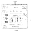
- Fig. 3 is an illustration of an exemplary CPU circuit board of the first processing unit of a control device according to the present invention.
- the CPU circuit board in question is located below the CAN trunk extension panel and is primarily responsible for work process management and communication with the trunk.
- the middle part is the first processor unit 1 comprising an ARM9 CPU and an intranet control device connected to this CPU, two SDRAMs (SDRAM1, SDRAM2) and one alternate memory (FLASH).
- the main plate is powered by a 24V DC power source 7 with electrical power.
- the above-described DC power source 7 not only provides the electric power to the main plate, but also supplies through the two in the figure on the right side of the CPU, the connectors below the I / O terminal plates with electrical power.
- a CD connector On the bottom of the CPU in the figure, a CD connector, an LCD connector, and a CAN main connector connector are provided.
- the communication between the CPU board and the CAN main board provided above it is practically realized by this CAN main line connector terminal referred to above.
- On the left side of the CPU board are two RS485 main line connectors, 2 USB ports (USB_A and USB_B), 1 intranet port, and 1 SD / MMC port.
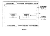
- FIG. 4 shows the illustration of the lowermost I / O board PCB2 of the three electrical circuits of the control device according to FIG. 2.
- I / O board 1 there are 24- Digital input, 2 analog inputs, 4 PT100 inputs for temperature measurement, 16 relay outputs, 2 isolated analog outputs and 16 24V triode outputs.
- the CPU main board PCB2 supplies electric power to the I / O board PCB3 through a port.
- I / O devices - ie I / O control device 10 and I / O device 20 - the corresponding communication. Because one controller does not have sufficient capacity for such numerous ports, two controllers are used here.
- the SPI main line can accommodate more I / O control devices to meet these needs.
- this requires the attachment of I / O devices in an appropriate number.
- 4 SPI ports are additionally provided on the I / O board PCB3 in Fig. 4 to effect the expansion of other SPI-connected device parts - for example, another I / O control device.
- Fig. 5 is an illustration of an I / O terminal circuit board PCB2 (for example, the PCB2 shown in Fig. 4) of a concrete embodiment of the utility model of the present invention. This is a possible embodiment of the functions of FIG. 4 on the electrical circuit.
- FIG. 6 an example of a topmost electrical expansion circuit PCB3 in the construction of Fig. 2 with three superimposed electrical circuit boards is shown.
- 3 CAN main line control devices and the three main lines generated are shown.
- This expansion plate is connected through an address data main line to the electrical circuit board PCB1 of the main control device.
- control device By using the control device according to the present invention, replacement of the second processor unit can easily ensure that new control devices are adapted to devices to be controlled, which are subject to variations in the type and / or number of connections.
- the control device according to the present invention is suitable for a wide application for industrial installations with control. For example, it can be used in complete automated industrial plants, in systems with numerical control, etc.
Landscapes
- Physics & Mathematics (AREA)
- General Physics & Mathematics (AREA)
- Engineering & Computer Science (AREA)
- Automation & Control Theory (AREA)
- Control By Computers (AREA)
- Selective Calling Equipment (AREA)
- Programmable Controllers (AREA)
Applications Claiming Priority (1)
| Application Number | Priority Date | Filing Date | Title |
|---|---|---|---|
| CNU2006200187112U CN2879256Y (zh) | 2006-03-30 | 2006-03-30 | 控制器 |
Publications (2)
| Publication Number | Publication Date |
|---|---|
| EP1840683A2 true EP1840683A2 (fr) | 2007-10-03 |
| EP1840683A3 EP1840683A3 (fr) | 2009-11-18 |
Family
ID=37861676
Family Applications (1)
| Application Number | Title | Priority Date | Filing Date |
|---|---|---|---|
| EP07105255A Withdrawn EP1840683A3 (fr) | 2006-03-30 | 2007-03-29 | Dispositif de contrôle |
Country Status (2)
| Country | Link |
|---|---|
| EP (1) | EP1840683A3 (fr) |
| CN (1) | CN2879256Y (fr) |
Cited By (1)
| Publication number | Priority date | Publication date | Assignee | Title |
|---|---|---|---|---|
| EP2362098A4 (fr) * | 2008-12-22 | 2017-03-22 | Mitsubishi Heavy Industries, Ltd. | Compresseur électrique à inverseur incorporé |
Families Citing this family (3)
| Publication number | Priority date | Publication date | Assignee | Title |
|---|---|---|---|---|
| CN106707888B (zh) * | 2017-02-16 | 2019-01-25 | 山东仕脉机器人技术有限公司 | 可编程控制模块及具有该控制模块的系统、控制方法 |
| CN109308058B (zh) * | 2018-10-25 | 2021-07-06 | 深圳丹弗科技有限公司 | 成功率改进的基于物联网的智能车床控制方法及系统 |
| CN115542809B (zh) * | 2022-09-30 | 2024-02-20 | 佛山食神网络智能科技有限公司 | 一种通用控制器 |
Family Cites Families (1)
| Publication number | Priority date | Publication date | Assignee | Title |
|---|---|---|---|---|
| WO2005062961A2 (fr) * | 2003-12-23 | 2005-07-14 | Rain Bird Corporation | Regulateur d'irrigation modulaire et extensible |
-
2006
- 2006-03-30 CN CNU2006200187112U patent/CN2879256Y/zh not_active Expired - Lifetime
-
2007
- 2007-03-29 EP EP07105255A patent/EP1840683A3/fr not_active Withdrawn
Cited By (1)
| Publication number | Priority date | Publication date | Assignee | Title |
|---|---|---|---|---|
| EP2362098A4 (fr) * | 2008-12-22 | 2017-03-22 | Mitsubishi Heavy Industries, Ltd. | Compresseur électrique à inverseur incorporé |
Also Published As
| Publication number | Publication date |
|---|---|
| CN2879256Y (zh) | 2007-03-14 |
| EP1840683A3 (fr) | 2009-11-18 |
Similar Documents
| Publication | Publication Date | Title |
|---|---|---|
| EP2182418B1 (fr) | Procédé et dispositif d'accès à un module de fonctionnement d'un système d'automatisation | |
| EP2751977B1 (fr) | Procédé pour faire fonctionner un appareil de terrain | |
| DE102008064674B4 (de) | Zentralbaugruppe für ein flexibles erweiterbares Automatisierungsgerät | |
| WO2001067190A2 (fr) | Procede de commande et installation de production industrielle equipee d'un systeme de commande par le web | |
| EP2683227B1 (fr) | Module électronique destiné à être inséré dans une unité de support | |
| EP1569055B1 (fr) | Dispositif de communication enfichable et procédé de communication utilisant un tel dispositif | |
| EP1840683A2 (fr) | Dispositif de contrôle | |
| EP1947568A1 (fr) | Procédé destiné à l'observation d'un appareil de commande | |
| EP0540903A1 (fr) | Elément de commande | |
| DE102017125815B4 (de) | Motorantriebsvorrichtung | |
| DE10359251A1 (de) | Vorrichtung zur Automatisierung von Werkzeug- oder Produktionsmaschinen | |
| DE102014016180A1 (de) | Verfahren und Einrichtung zur Verwaltung und Konfiguration von Feldgeräten einer Automatisierungsanlage | |
| EP3088976B1 (fr) | Procédé de fonctionnement d'un dispositif d'automatisation et dispositif d'automatisation | |
| EP2698677A1 (fr) | Système périphérique | |
| EP4123396B1 (fr) | Technique destinée à la réalisation d'une visualisation pour une installation technique d'automatisation dotée d'une commande à mémoire programmable | |
| DE10243771A1 (de) | Vorrichtung zur Automatisierung und/oder Steuerung von Werkzeug- oder Produktionsmaschinen | |
| AT509181A2 (de) | Multifunktionales ein- und ausgangsmodul für speicherprogrammierbare steuerungen | |
| EP2806316B1 (fr) | Procédé destiné au fonctionnement d'un système d'automatisation | |
| WO2004046973A2 (fr) | Saisie orientée sur la topologie d'informations d'automatisation | |
| DE3116471C2 (fr) | ||
| BE1031761B1 (de) | Verfahren und Vorrichtung zur Prüfung eines Schaltungsaufbaus | |
| EP2735925B1 (fr) | Dispositif d'automatisation | |
| DE10215121A1 (de) | Verfahren zum Projektieren und/oder Betreiben einer Automatisierungseinrichtung | |
| DE19828024B4 (de) | Regelanordnung zur Regelung von wenigstens einem an einem Bussystem angeschlossenen Positionierantrieb, insbesondere pneumatischen Positionierantrieb | |
| EP4435542A1 (fr) | Procédé d'assistance automatique d'ingénierie intra-dustratique, produit programme informatique pour la mise en uvre du procédé et dispositif |
Legal Events
| Date | Code | Title | Description |
|---|---|---|---|
| PUAI | Public reference made under article 153(3) epc to a published international application that has entered the european phase |
Free format text: ORIGINAL CODE: 0009012 |
|
| AK | Designated contracting states |
Kind code of ref document: A2 Designated state(s): AT BE BG CH CY CZ DE DK EE ES FI FR GB GR HU IE IS IT LI LT LU LV MC MT NL PL PT RO SE SI SK TR |
|
| AX | Request for extension of the european patent |
Extension state: AL BA HR MK YU |
|
| PUAL | Search report despatched |
Free format text: ORIGINAL CODE: 0009013 |
|
| AK | Designated contracting states |
Kind code of ref document: A3 Designated state(s): AT BE BG CH CY CZ DE DK EE ES FI FR GB GR HU IE IS IT LI LT LU LV MC MT NL PL PT RO SE SI SK TR |
|
| AX | Request for extension of the european patent |
Extension state: AL BA HR MK RS |
|
| AKX | Designation fees paid | ||
| STAA | Information on the status of an ep patent application or granted ep patent |
Free format text: STATUS: THE APPLICATION IS DEEMED TO BE WITHDRAWN |
|
| 18D | Application deemed to be withdrawn |
Effective date: 20100519 |
|
| REG | Reference to a national code |
Ref country code: DE Ref legal event code: 8566 |