EP1840871A1 - Vorrichtung, verfahren und programm zur audiowellenformverarbeitung - Google Patents
Vorrichtung, verfahren und programm zur audiowellenformverarbeitung Download PDFInfo
- Publication number
- EP1840871A1 EP1840871A1 EP05842258A EP05842258A EP1840871A1 EP 1840871 A1 EP1840871 A1 EP 1840871A1 EP 05842258 A EP05842258 A EP 05842258A EP 05842258 A EP05842258 A EP 05842258A EP 1840871 A1 EP1840871 A1 EP 1840871A1
- Authority
- EP
- European Patent Office
- Prior art keywords
- waveform
- band
- phase
- audio
- synthesis process
- Prior art date
- Legal status (The legal status is an assumption and is not a legal conclusion. Google has not performed a legal analysis and makes no representation as to the accuracy of the status listed.)
- Granted
Links
Images







Classifications
-
- G—PHYSICS
- G10—MUSICAL INSTRUMENTS; ACOUSTICS
- G10L—SPEECH ANALYSIS TECHNIQUES OR SPEECH SYNTHESIS; SPEECH RECOGNITION; SPEECH OR VOICE PROCESSING TECHNIQUES; SPEECH OR AUDIO CODING OR DECODING
- G10L21/00—Speech or voice signal processing techniques to produce another audible or non-audible signal, e.g. visual or tactile, in order to modify its quality or its intelligibility
- G10L21/04—Time compression or expansion
-
- G—PHYSICS
- G10—MUSICAL INSTRUMENTS; ACOUSTICS
- G10L—SPEECH ANALYSIS TECHNIQUES OR SPEECH SYNTHESIS; SPEECH RECOGNITION; SPEECH OR VOICE PROCESSING TECHNIQUES; SPEECH OR AUDIO CODING OR DECODING
- G10L19/00—Speech or audio signals analysis-synthesis techniques for redundancy reduction, e.g. in vocoders; Coding or decoding of speech or audio signals, using source filter models or psychoacoustic analysis
- G10L19/02—Speech or audio signals analysis-synthesis techniques for redundancy reduction, e.g. in vocoders; Coding or decoding of speech or audio signals, using source filter models or psychoacoustic analysis using spectral analysis, e.g. transform vocoders or subband vocoders
-
- G—PHYSICS
- G10—MUSICAL INSTRUMENTS; ACOUSTICS
- G10L—SPEECH ANALYSIS TECHNIQUES OR SPEECH SYNTHESIS; SPEECH RECOGNITION; SPEECH OR VOICE PROCESSING TECHNIQUES; SPEECH OR AUDIO CODING OR DECODING
- G10L21/00—Speech or voice signal processing techniques to produce another audible or non-audible signal, e.g. visual or tactile, in order to modify its quality or its intelligibility
- G10L21/003—Changing voice quality, e.g. pitch or formants
- G10L21/007—Changing voice quality, e.g. pitch or formants characterised by the process used
- G10L21/013—Adapting to target pitch
-
- G—PHYSICS
- G11—INFORMATION STORAGE
- G11B—INFORMATION STORAGE BASED ON RELATIVE MOVEMENT BETWEEN RECORD CARRIER AND TRANSDUCER
- G11B20/00—Signal processing not specific to the method of recording or reproducing; Circuits therefor
- G11B20/10—Digital recording or reproducing
-
- G—PHYSICS
- G10—MUSICAL INSTRUMENTS; ACOUSTICS
- G10L—SPEECH ANALYSIS TECHNIQUES OR SPEECH SYNTHESIS; SPEECH RECOGNITION; SPEECH OR VOICE PROCESSING TECHNIQUES; SPEECH OR AUDIO CODING OR DECODING
- G10L19/00—Speech or audio signals analysis-synthesis techniques for redundancy reduction, e.g. in vocoders; Coding or decoding of speech or audio signals, using source filter models or psychoacoustic analysis
- G10L19/02—Speech or audio signals analysis-synthesis techniques for redundancy reduction, e.g. in vocoders; Coding or decoding of speech or audio signals, using source filter models or psychoacoustic analysis using spectral analysis, e.g. transform vocoders or subband vocoders
- G10L19/0204—Speech or audio signals analysis-synthesis techniques for redundancy reduction, e.g. in vocoders; Coding or decoding of speech or audio signals, using source filter models or psychoacoustic analysis using spectral analysis, e.g. transform vocoders or subband vocoders using subband decomposition
Definitions
- the present invention relates to audio waveform processing for performing time stretching and pitch shifting by a vocoder method.
- Time stretching is a process of expanding and compressing only a time axis of an audio waveform without changing a pitch thereof.
- Pitch shifting is a process of changing only the pitch without changing the time axis.
- vocoder method as a heretofore known audio waveform processing for performing the time stretching and the pitch shifting (refer to Patent Document 1 for instance). This method analyzes a frequency of an inputted audio waveform, compresses or expands the time axis on the time stretching, and scales the frequency of an outputted waveform and then adds each frequency component on the pitch shifting.
- FIGS. 7A and 7B show the change in the phase generated when time-stretching a certain 2-channel stereo audio waveform as an example.
- a horizontal axis of a graph represents the time axis, and a vertical axis represents the phase of the frequency component.
- FIG. 7A shows phase changes of components A and B in a frequency band having two channels obtained as a result of frequency analysis of the audio input waveform.
- FIG. 7B shows phases of A1 and B1 corresponding to A and B obtained when the waveform of FIG. 7A is time-compressed to 1/2 by the vocoder method.
- the time axis becomes 1/2 times
- the vertical axis representing the phase also becomes 1/2 times.
- phase difference between A and B at the time T is 2 ⁇ , and hence the phase difference is 0 if expressed as - ⁇ to ⁇ .
- the components A and B undergo a transition with the phase difference of 0 even after the time T.
- the phase difference between A1 and B1 at the time T1 after the time compression is ⁇ , and A1 and B1 undergo a transition with the phase difference ⁇ even after the time T1.
- the phase relation between A1 and B1 has apparently changed from that of A and B before the time compression.
- the vocoder method expands and compresses the time axis so that a lag or a lead of the phase occurs by the amount of expansion and compression.
- This also applies to the pitch shifting.
- a phase change amount is different among the frequency components having undergone the frequency analysis, and is also different among the channels in the case of a stereo audio. For this reason, there arises an auditory sense of discomfort due to, for example, mutual cancellation of sounds or a lack of feeling of normalcy of a stereo sound. Therefore, the time stretching and the pitch shifting of high quality cannot be realized.
- Patent Document 1 discloses an audio waveform device wherein attention is focused on a pre-echo generated on performing band division in an attack portion, in which a level of the audio waveform greatly changes, and the phase is reset at the beginning of a section of the pre-echo.
- Patent Document 1 Japanese Patent Application Laid-Open No. 2001-117595
- Patent Document 1 the audio waveform device disclosed in Patent Document 1 was made in view of keeping an attack feeling, and no notice is taken of the phase change after the attack. There is also a problem that it is difficult to detect the attack portion as to a complicatedly mixed tune.
- the present invention relates to the audio waveform processing for performing the time stretching and the pitch shifting by the vocoder method, and an object thereof is to realize audio waveform processing of high quality which does not cause auditory sense of discomfort, and which reduces the phase change invariably occurring in the vocoder method through the entire waveform.
- an audio waveform processing device, a method, and a program thereof according to the present invention handle an audio input waveform as-is as one band (the band refers to a frequency band, and the frequency band is hereinafter referred to as the band) or divide it into multiple bands by the frequency band, synthesize the waveform while performing time expansion/compression and pitch conversion to each band waveform as with the conventional vocoder method, and perform phase synchronization processing to a synthesized waveform of each band at regular intervals so as to reduce the phase change. Furthermore, the waveforms of respective bands after the phase synchronization processing are added to be a final output waveform.
- the invention as set forth in claim 1 is an audio waveform processing device for performing a frequency analysis on an audio waveform and performing a sine wave or cosine wave synthesis process on each frequency component while performing time compression or expansion and pitch conversion as required, configured so that the frequency analysis and the synthesis process are performed as to each band of an audio signal divided into multiple frequency bands; similarity between an original waveform and a waveform after the synthesis process of each band is evaluated; and a cross-fade process is performed from the waveform after the synthesis process to the band original waveform at locations of high similarity so as to reset a phase change occurring on the waveform synthesis.
- the invention is characterized by synthesizing each band waveform divided by the frequency band while performing the time expansion/compression and the pitch conversion by the vocoder method and performing the phase synchronization processing to the synthesized waveform.
- the invention as set forth in claim 2 is the audio waveform processing device, configured so that, in the frequency band division of the device set forth in claim 1, the audio waveform is processed by regarding it as one band as-is without performing the band division.
- the invention is characterized by handling the audio waveform as-is as one band, synthesizing it while performing the time expansion/compression and the pitch conversion by the vocoder method and performing the phase synchronization processing to the synthesized waveform.
- the invention as set forth in claim 3 is an audio waveform processing method of performing a frequency analysis on an audio waveform and performing a sine wave or cosine wave synthesis process on each frequency component while performing time compression or expansion and pitch conversion as required, configured so that the frequency analysis and the synthesis process are performed as to each band of an audio signal divided into multiple frequency bands; similarity between an original waveform and a waveform after the synthesis process of each band is evaluated; and a cross-fade process is performed from the waveform after the synthesis process to the band original waveform at locations of high similarity so as to reset a phase change occurring on the waveform synthesis.
- the invention is characterized by synthesizing each band waveform divided by the frequency band while performing the time expansion/compression and the pitch conversion by the vocoder method and performing the phase synchronization processing to the synthesized waveform.
- the invention as set forth in claim 4 is the audio waveform processing method, configured so that, in the frequency band division of the method set forth in claim 3, the audio waveform is processed by regarding it as one band as-is without performing the band division.
- the invention is characterized by handling the audio waveform as-is as one band, synthesizing it while performing the time expansion/compression and the pitch conversion by the vocoder method and performing the phase synchronization processing to the synthesized waveform.
- the invention as set forth in claim 5 is a computer program, comprising an instruction group for causing a computer to execute the audio waveform processing method set forth in any one of claims 3 and 4.
- the invention is characterized by realizing the phase synchronization processing with the computer program.
- the invention as set forth in claim 6 is an audio waveform processing device for performing a frequency analysis on an audio waveform and performing a sine wave or cosine wave synthesis process on each frequency component while performing time compression or expansion and pitch conversion as required, configured so that the frequency analysis is performed as to each band of an audio signal divided into multiple frequency bands; a comparison is made by using an evaluation function between a phase condition after the waveform synthesis process of each band and a phase condition of an original waveform of each band to generate a waveform having a linear phase lead or a linear phase lag with respect to the original waveform highly correlated with the phase condition after the synthesis process as a phase synchronization waveform; and a cross-fade process is performed from the waveform after the synthesis process to the generated phase synchronization waveform in a phase synchronization processing period so that a phase change occurring on the waveform synthesis is reset in the phase synchronization processing period.
- the invention as set forth in claim 7 is the audio waveform processing device, configured so that, in the frequency band division of the device set forth in claim 6, the audio waveform is processed by regarding it as one band as-is without performing the band division.
- the invention as set forth in claim 8 is an audio waveform processing method of performing a frequency analysis on an audio waveform and performing a sine wave or cosine wave synthesis process on each frequency component while performing time compression or expansion and pitch conversion as required, configured so that the frequency analysis is performed as to each band of an audio signal divided into multiple frequency bands; a comparison is made by using an evaluation function between a phase condition after the waveform synthesis process of each band and a phase condition of an original waveform of each band to generate a waveform having a linear phase lead or a linear phase lag with respect to the original waveform highly correlated with the phase condition after the synthesis process as a phase synchronization waveform; and a cross-fade process is performed from the waveform after the synthesis process to the generated phase synchronization waveform in a phase synchronization processing period so that a phase change occurring on the waveform synthesis is reset in the phase synchronization processing period.
- the invention as set forth in claim 9 is the audio waveform processing method, configured so that, in the frequency band division of the method set forth in claim 8, the audio waveform is processed by regarding it as one band as-is without performing the band division.
- the invention as set forth in claim 10 is a computer program including an instruction group for causing a computer to execute the audio waveform processing method set forth in any one of claims 8 and 9.
- the invention as set forth in claim 11 is the audio waveform processing device set forth in claims 6 and 7, wherein a distance on a complex-number plane between the waveforms is used as the evaluation function for evaluating a difference between the phase condition after the waveform synthesis process of each band and the phase condition of the original waveform of each band.
- the invention as set forth in claim 12 is the audio waveform processing method as set forth in claims 8 and 9, wherein a distance on a complex-number plane between the waveforms is used as the evaluation function for evaluating a difference between the phase condition after the waveform synthesis process of each band and the phase condition of the original waveform of each band.
- the invention as set forth in claim 13 is the computer program according to claim 10, wherein a distance on a complex-number plane between the waveforms is used as the evaluation function in a computer program operation for evaluating a difference between the phase condition after the waveform synthesis process and the phase condition of the original waveform of each band.
- the phase synchronization processing of the present invention is to evaluate similarities of the synthesized waveform having undergone the time expansion/compression and the pitch conversion in each band to its original band waveform by shifting time series and to perform the cross-fade process on a location determined to be highly similar so as to turn the synthesized wave form back to the original band waveform.
- the waveform at a time point when the phase synchronization processing is finished that is the time point when the cross-fade process is finished is in the same phase condition as the original band waveform. Evaluation of the similarities is intended to lessen discontinuities caused by the cross-fade process and to obtain the waveform which does not cause an auditory sense of discomfort.
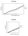
- FIGS. 8A and 8B show the effects of the phase synchronization processing.
- FIG. 8A shows the phase condition of the same audio input waveform as FIG. 7A.
- Reference characters A2 and B2 denote phases of frequency components corresponding to A and B of FIG. 8A respectively.
- phase relation between A1 and B1 at time T1 has changed from its original form.
- the phase of A2 is 6.5 ⁇ and the phase of B2 is 8.5 ⁇ at the time T1 when the phase synchronization processing is performed. It can be seen that the difference is 2 ⁇ and so there is no longer the phase difference so that the same phase relation as that between the original A and B is kept.
- phase relation of the original waveform is kept by the phase synchronization processing to the synthesized waveform having undergone time stretch and pitch shift processing by the vocoder method.
- the phase synchronization processing is performed at regular intervals so that the phase relation of the original waveform is kept each time, which consequently allows the time stretch and pitch shift processing to eliminate auditory sense of discomfort with the phase change reduced through the entire waveform.
- the frequency analysis and the synthesis process of the audio signal are performed as to each of the bands divided into multiple frequency bands to evaluate the similarity between the original waveform and the waveform after the synthesis process as to each band.
- the cross-fade process is performed at the locations of high similarity between the waveform after the synthesis process and the band original waveform so that the phase change occurring on the waveform synthesis can be reset.
- the similarity between the original waveform and the waveform after the synthesis process is evaluated by regarding the audio waveform as-is as one band without performing the band division.
- the cross-fade process is performed at the locations of high similarity between the waveform after the synthesis process and the original waveform so that the phase change occurring on the waveform synthesis can be reset.
- the audio waveform processing method described in one of claims 3 and 4 can be performed by a commercially available audio processing program for a personal computer so that vocoder-method audio processing of high quality can be realized at even lower prices.
- the frequency analysis and the synthesis process are performed as to each of the bands of the audio signal divided into multiple frequency bands.
- the phase condition after the synthesis process of each band is compared with the phase condition of the original waveform to generate the waveform which is highly correlated with the phase condition after the synthesis process and is a linear phase lead or a linear phase lag of the original waveform as a phase synchronization waveform.
- the cross-fade process is performed to turn the waveform after the synthesis process to a movement synchronization waveform so that the phase change occurring on the waveform synthesis can be reset.
- the audio waveform is processed by regarding it as-is as one band without performing the band division in the frequency band division of the device according to claim 6.
- the audio waveform processing method described in one of claims 8 and 9 can be performed by a commercially available audio processing program for a personal computer so that vocoder-method audio processing of high quality can be realized at even lower prices.
- a distance on a complex-number plane between the waveforms is used as an evaluation function for evaluating the difference between the phase condition after the waveform synthesis process of each band and the phase condition of the original waveform of each band.
- the effect of using the audio waveform processing device, method, and program of the present invention is that, whether the audio input waveform is monaural or stereo, the phase change invariably occurring in the conventional vocoder method is reduced through the entire waveform so that the time stretch and pitch shift processing of high quality can be realized.
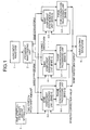
- FIG. 1 shows a block diagram of audio waveform processing according to claims 1 and 3, which is a first embodiment of the present invention. Audio waveforms handled in this embodiment are digitized.
- An audio input waveform 1 is divided into several bands by a frequency band dividing unit 2. This embodiment divides it into six bands.
- Reference numeral 3 denotes a time stretch/pitch shift amount setting unit, where a parameter is changed by an operation by a user.
- Band waveforms generated by the frequency band dividing unit 2 undergo a frequency analysis by band component synthesizing units 4-0 to 4-5, and the waveforms are synthesized according to a time stretch/pitch shift amount set based on a result of the frequency analysis while time expansion/compression and pitch conversion are performed.
- phase synchronization processing units 5-0 to 5-5 perform phase synchronization processing by using the waveforms synthesized by the band component synthesizing units 4 and a band original waveform generated by the frequency band dividing unit 2.
- An audio output wave form 6 is a result of additively synthesizing output waveforms of the phase synchronization processing units 5 of respective bands.
- a correction value is fed back to the band component synthesizing units 4 so as to uniform the lengths of the waveforms outputted on performing synthesizing process next.
- the frequency band dividing unit 2 and the bands thereof are desirable to set the number of bands to be divided by the frequency band dividing unit 2 and the bands thereof in accordance with the audio input waveform.
- the number of divisions must be increased as to a complicatedly mixed tune.
- the phase synchronization processing is performed on a per-band basis so that phase change in the band is reduced.
- the phase relation among the bands may collapse. For that reason, it is necessary to use an adequate number of divisions and bands which are not too many.
- the audio input waveform such as music can be adequately processed when divided into a bandwidth which is one octave or so as a music scale.
- FIG. 2 shows details of the band component synthesizing unit 4 of FIG. 1 in a block diagram.
- Reference numeral 7 denotes a time stretch amount correction processing unit, which corrects a stretch amount and adds a phase reset signal in the case where an error occurs to a length of the output waveform in the phase synchronization processing units 5.
- a channel division processing unit 8 of FIG. 2 divides the band waveform generated by the frequency band dividing unit 2 of FIG. 1 into channels.
- the number of divisions in this case is different according to the number of channels of the audio input waveform.
- the frequency analysis and the time stretch/pitch shift processing thereafter are performed as to each of the divided channels.
- FIG. 12 shows a waveform data flow of the channel division processing unit 8 of FIG. 2.
- a stereo waveform memory 36 has waveform data of two channels placed in one bundle therein, and the data of each channel is rearranged in a channel 0 waveform memory 37 and a channel 1 waveform memory 38 and is passed to frequency analysis units 9-0 and 9-1.
- the same process is also possible by passing an initial address of each channel in the waveform memory 36 to the frequency analysis units 9-0 and 9-1 instead of rearranging the data.
- the frequency analysis units 9-0 and 9-1 of FIG. 2 calculate frequencies, phases, and amplitudes included in the waveforms divided by the channel division processing unit 8 by using an STFFT (Short-Time Fast Fourier Transform).
- STFFT Short-Time Fast Fourier Transform
- the length of the audio waveform analyzable by the STFFT at one time is decided by a window function to be used and an FFT size. This length is defined as one frame, and a waveform synthesis subsequently described is performed frame by frame. For instance, in the case of processing a digital audio waveform discretized at 44.1 kHz, 1024 points are used as the window function and FFT size.
- a width on a time axis is approximately 23.2 msec, and the data per approximately 43 Hz is acquired on a frequency axis with a good balance between a frequency resolution and a time resolution.
- the FFT size is rendered larger.
- the FFT size is rendered smaller.
- Square root and arctangent operations are performed from the data calculated by the FFT.
- the data on an amplitude AS/AE, a phase PS/PE, and an instantaneous angular frequency W of the frequency component is stored in a memory address. It is adequate that the bandwidth of one frequency component is one halftone or so as the music scale. In the case where the bands are divided into 1-octave bandwidths by the frequency band dividing unit 2, twelve.pieces of frequency component data are calculated.
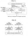
- time stretch/pitch shift processing units 10-0 to 10-1 of FIG. 2 synthesize the waveforms according to the result analyzed by the frequency analysis units 9 and the required time stretch/pitch shift amounts.
- Sine or cosine oscillation is performed for each frequency component, and those are additively synthesized to acquire a synthesized waveform.
- the time axis for synthesizing the waveform is compressed or expanded according to the time stretch amount required in this case. Amplitude values are interpolated so that the amplitudes will not be discontinuous due to compression or expansion of the time axis.
- the angular frequency of oscillation is scaled according to the required pitch shift amount.
- the phase when starting the oscillation the phase calculated by the frequency analysis units 9 is set on an initial operation or when a phase reset signal is inputted. In other cases, the phase on finishing the oscillation of a previous frame is used as-is, and processing is performed so that the waveforms are smoothly connected between the frames. A configuration of these processes is as shown in FIG. 14.
- the synthesized waveform data is stored in the memory and passed to a channel integration processing unit 11.
- the channel integration processing unit 11 renders the waveforms synthesized per channel by the time stretch/pitch shift processing units 10 stereo so as to have the same number of channels as the.audio input waveforms.
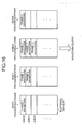
- FIG. 15 shows a data flow of the channel integration processing unit 11.
- the waveforms stored in a channel 0 synthesized waveform memory 39 and a channel 1 synthesized waveform memory 40 are rearranged in one bundle in a stereo synthesized waveform memory 41.
- the stereo-rendered audio waveforms after the band component synthesis are further processed by the phase synchronization processing unit 5.
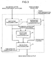
- FIG. 3 shows details of the phase synchronization processing unit 5 of FIG. 1 in a block diagram.
- the waveform for one frame generated by the band component synthesizing unit 4 of FIG. 1 is once accumulated in a buffering processing unit 12 of FIG. 3. This is because the phase synchronization processing requires the waveform of a certain length, and there are the cases where the length of one frame is not sufficient.
- the number of frames necessary for the phase synchronization processing is different as to each of the bands having undergone frequency band division. Evaluation of similarity in the phase synchronization processing described later requires periodic components included in the synthesized waveforms equivalent to several waveforms. And the length of the waveform necessary for that purpose is long as to a low-frequency band and short as to a highfrequency band.
- the number of frames is taken too long, intervals of the phase synchronization processing become wider so that the phase change becomes great enough to cause an auditory sense of discomfort due to the phase change to be perceived. It is desirable to use an adequate number of frames by considering the frequency band and auditory quality of the band. If the number of frames is within 40 msec as a time length, the discomfort due to the phase change is not so perceivable. As a wavelength becomes long on the low-frequency band, however, the number of frames of over 40 msec including the waveforms of five wavelengths or so is used.
- FIG. 16 shows memory usage of the buffering processing unit. In FIG. 16, it is presumed that the length of the waveform necessary for the phase synchronization processing is 3 frames, the waveforms are outputted if the band synthesized waveforms equivalent to 3 frames are accumulated, and the synthesized waveform of the fourth frame is placed at a head of a buffering memory.
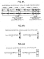
- FIG. 4A shows how the band original waveforms correspond to the frames, where the phase synchronization processing occurs after the processing of the frame 3 and the frame 6.
- FIG. 4A the waveforms are drawn in two tiered stages, and the respective channels of a stereo audio waveform are dividedly drawn.
- FIG. 4B shows the reference waveforms in the respective phase synchronization processing in the case where there is no pitch shift.
- FIG. 4C shows the reference waveforms in the case where there is the pitch shift.
- an example of the case of pitch-shifting to 1/2 is shown.
- the waveforms of FIG. 4B are simply scaled against the time axis, and an expansion rate of the time axis is 1/ ⁇ if the value of frequency scaling of the pitch-shift is ⁇ .
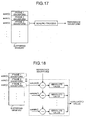
- FIG. 17 shows the data flow of the reference waveform generation unit 13 of FIG. 3.
- the waveform data is read from the address of the end of the third frame, and the scaling of the time axis is performed according to the pitch shift amount so as to output the reference waveform.
- a waveform similarity evaluation unit 14 of FIG. 3 evaluates at what time point on the time axis the similarity of two waveforms is high by using the waveform accumulated in the buffering processing unit 12 and the waveform generated by the reference waveform generation unit 13.
- the location of high similarity acquired here is used as a cross-fade position in the subsequent cross-fade process.
- an arbitrary evaluation function for evaluating similarity is prepared, and the evaluation function is executed for the buffered band synthesized waveform while shifting the time axis so as to acquire the time point of the highest evaluated value as a result.
- an absolute value of a difference between the band synthesized waveform and the reference waveform is calculated at each sample point to use a result of adding them up as the evaluated value.
- FIG. 18 specifically describes this evaluation method.
- the number of sample points of the reference waveform is l r .
- a part of the waveform data stored in the buffer is taken out, and the absolute value of the difference from the reference waveform is calculated as to all the n pieces of sample point to acquire the sum thereof as the evaluated value.
- the waveform is cut out by shifting the address of the buffering memory, and the evaluated value is calculated as to the entire waveform data. Of the evaluated values thus calculated, it can be said that a smaller value indicates a smaller difference in the waveform and higher similarity.
- the cross-fade process is performed to return from the band synthesized waveform buffered by a cross-fade processing unit 15 to the reference waveform by using the waveform generated by the reference waveform generation unit 13 and the cross-fade position calculated by the waveform similarity evaluation unit 14.
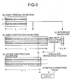
- FIG. 5 A description will be given as to the concept of the phase synchronization processing described so far with reference to an example shown in FIG. 5.
- two channels of the stereo audio waveform are dividedly drawn in two tiered stages, which indicates that the reference waveform generation, similarity evaluation, and cross-fade process are performed in stereo.
- a portion (a) of FIG. 5 shows the band original waveform which is presumed undergoing twice time-stretching.
- the length of the band original waveform of the portion (a) of FIG. 5 is l 1 .
- a band synthesized waveform (b) of FIG. 5 stretched to twice and accumulated in the buffering processing unit 12 of FIG. 3 and a reference waveform (c) of FIG. 5 generated by the reference waveform generation unit 13 are obtained respectively.
- the length of the reference waveform (c) in FIG. 5 is l r .
- the similarity of these waveforms is evaluated by the similarity evaluation unit 14 of FIG. 3, and the calculated cross-fade position of FIG. 5 is t cf .
- the cross-fade process of FIG. 5 is performed in the range of the length corresponding to the reference wave form from the calculated cross-fade position t cf , that is, the section from t cf to t cf + l r .
- a portion (d) in FIG. 5 shows the waveform after the cross-fade process.
- the end of the waveform after finishing the cross-fade process has the same value as the end of the reference waveform. To be more specific, it returns to the same phase condition (is phase-synchronized) as the band original waveform. Even if the audio input waveform is stereo, the phase relation between the channels is kept by the processing. This portion deserves special mention in the present invention.
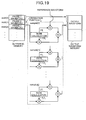
- FIG. 19 shows details of the cross-fade process.
- the length of the waveform necessary for the phase synchronization processing is equivalent to three frames.
- the waveforms from the cross-fade position t cf onward accumulated in the buffering memory undergo rate calculation and multiplication as to each sample point.
- the reference waveform undergoes the rate calculation and multiplication so as to output the sum of the values after the multiplication.
- the rate calculations in FIG. 19 indicate an example of cross-fades by linear interpolation.
- the waveforms prior to the cross-fade position t cf are stored as-is as the output waveforms in an output waveform memory.
- the waveform after finishing the cross-fade process becomes a band output waveform as-is.
- the length thereof is t cf + l r which is shorter than the length l 2 of an original stretched waveform.
- the portion equivalent to the length of l 2 - (t cf + l r ) remaining after t cf + l r is discarded, that length occurs as an error in the phase synchronization processing.
- the value of the error is passed as a stretch correction value to a time stretch amount correction processing unit 7 in the band component synthesizing unit of FIG. 2.
- the waveform synthesis is performed by adding the length of the error in the next frame so as to keep the length of the original waveform.
- the above process is performed to each of the bands so as to acquire a final audio output waveform by adding them.
- FIG. 6 shows an audio signal waveform processing device as an embodiment according to the present invention.
- This example reproduces and outputs the audio waveform on recording media such as a hard disk drive 19 and a CD-ROM drive 20 while performing the time stretching and pitch shifting.
- the present invention is not limited to this example, and the audio waveform processing device of the present invention can be mounted on various instruments, such as a sampler and an electronic musical instrument.
- a CPU 16 is a central processing unit for exerting overall control of the device
- a ROM 17 is a read-only memory storing a control program
- a RAM 18 is a random access memory utilized as a memory work area and the like.
- the hard disk drive 19 and the CD-ROM drive 20 are external storage devices which are used as inputs of the audio waveforms.
- a speech output unit 21 is composed of a D/A converter for converting a digital audio waveform to analog and a speaker.
- a controller group 22 is various switches and the like.
- An indicator 230 is an indicator used to display parameters on the screen when selecting the time stretch/pitch shift amount.
- a program composed of an instruction group for causing a computer to execute an audio waveform processing method of the present invention is stored in the ROM 17.
- the CPU 16 performs waveform processing to the audio waveforms of the hard disk drive 19 and the CD-ROM drive 20 while using the RAM 18 as a working memory, and the result is outputted as sound from the speaker of the speech output unit 21. It is possible, with the above configuration, to realize an audio reproducing device which performs the time stretch/pitch shift processing of high quality to music recorded on a hard disk and a CD-ROM.
- the first embodiment has described the example of implementing the waveform processing by performing the band division on the audio input waveform. It is possible, however, to implement the same waveform processing as that described in the first embodiment by using the means disclosed in claims 2 and 4 which do not perform the band division on the audio input waveform.
- the frequency band dividing unit 2, the band component synthesizing unit (band 1) 4-1 to the band component synthesizing unit (band 5) 4-5, and the phase synchronization processing unit (band 1) 5-1 to the phase synchronization processing unit (band 5) 5-5 are deleted, and the audio input waveform 1 is directly inputted to the band component synthesizing unit (band 0) 4-0 and perform the same waveform processing as that described in the first embodiment.
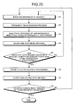
- FIG. 20 shows a flowchart of the computer program.
- input waveform data is read (step S1), and a frequency band dividing process (step S2) which is the same as the frequency band dividing unit 2 of FIG. 1 is performed so as to output the waveform of each band.
- This process is composed of an instruction group such as multiplications and additions for realizing the band-pass filter or an instruction group for executing FFT in the case of realizing the band division by Fourier transform.
- step S3 an analytical process is performed as to instantaneous amplitude, angular frequency, and phases of band waveform data having undergone the frequency band division (step S3).
- This process is a part equivalent to the frequency analysis units 9-0 to 9-1 of FIG. 2, and is composed of the instruction group for executing the FFT and instruction groups of square roots for calculating the amplitude, arctans for calculating the phases, and the like.
- a waveform synthesis process (step S4) is executed based on the analyzed data.
- This process is the same process as that of the time stretch/pitch shift processing units 10-0 to 10-1 of FIG. 2. It is composed of instruction groups such as cosine functions for playing a role of an oscillator and multiplications for multiplying the amplitudes, where a time stretched and/or pitch-shifted waveform is synthesized.
- step S5 it is determined whether or not the length of the synthesized waveform has reached the length necessary for the phase synchronization processing (step S5). In the case where the necessary length has not been reached, the procedure returns to the step S1 to repeat the process until the necessary length is reached while accumulating the synthesized waveforms in the memory. In the case where the necessary length has been reached, the procedure moves on to the next step. This process is the same process as that of the buffering processing unit 12 of FIG. 3.
- phase synchronization processing (step S6) is performed to the synthesized waveform.
- This processing is equivalent to the processing of the reference waveform generation unit 13, the waveform similarity evaluation unit 14, and the cross-fade processing unit 15 of FIG. 3.
- This processing is composed of an instruction group of subtractions for executing the evaluation function of similarity and the like and an instruction group of multiplications and additions for performing the cross-fade process.
- step S2 to the step S6 is performed as to each of the bands having undergone the band division, and output waveform data of each band is added up to execute output waveform data writing (step S7).
- An instruction of addition is used to add up the output waveform data of the bands.
- step S8 it is determined whether or not the processing has been finished as to the entire input waveform. If the processing has not been finished, the procedure returns to the step S1 to repeat the processing. If the processing has been finished as to the entire input waveform, the processing is finished.
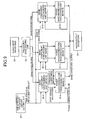
- FIG. 9 shows a block diagram of audio waveform processing as a fourth embodiment.
- the audio waveform handled in this embodiment is digitized.
- An audio input waveform 23 is divided into several bands by a frequency band dividing unit 24.
- the audio input waveform 23 is divided into six bands in this embodiment.
- Reference numeral 25 denotes a time stretch/pitch shift amount setting unit, where a parameter is changed by an operation by the user.
- Band waveforms generated by the frequency band dividing unit 24 undergo a frequency analysis by band component synthesizing units 26-0 to 26-5, and the waveforms are synthesized according to a time stretch/pitch shift amount set based on a result of the analysis while the time expansion/compression and the pitch conversion are performed.
- phase synchronization processing units 27-0 to 27-5 perform the phase synchronization processing by using the waveforms synthesized by the band component synthesizing units 26 and frequency component information.
- An audio output waveform 28 is a result of additively synthesizing output waveforms of the phase synchronization processing units 27 of respective bands.
- the phase condition of the synthesized waveform is a linear phase lead or a linear phase lag of the original waveform in the phase synchronization processing unit 27, a phase correction value is fed back to the band component synthesizing units 26 so as to correct a phase value to be applied on the next synthesis process.
- the frequency band dividing unit 24 and the bands thereof are desirable to set the number of bands to be divided by the frequency band dividing unit 24 and the bands thereof in accordance with the audio input waveform.
- the number of divisions must be increased as to a complicatedly mixed tune.
- the phase synchronization processing is performed on a per-band basis so that the phase change in the band is reduced.
- the phase relation among the bands may collapse. For that reason, it is necessary to use an adequate number of divisions and bands which are not too many.
- the audio input waveform such as music can be adequately processed when divided into a bandwidth which is one octave or so as a music scale.
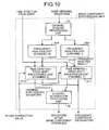
- FIG. 10 shows details of the band component synthesizing unit 26 of FIG. 9 in a block diagram.
- a channel division processing unit 29 divides the band waveform generated by the frequency band dividing unit 24 into channels. The number of divisions in this case is different according to the number of channels of the audio input waveform. The frequency analysis and the time stretch/pitch shift processing thereafter are performed as to each of the divided channels.
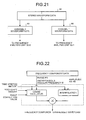
- FIG. 21 shows a waveform data flow of the channel division processing unit 29 of FIG. 10.
- a stereo waveform memory 42 has waveform data of two channels placed in one bundle therein, and the data of each channel is rearranged in a channel 0 waveform memory 43 and a channel 1 waveform memory 44 and is passed to frequency analysis units 30-0 to 30-1.
- the same process is also possible by passing an initial address of each channel in the waveform memory 36 to the frequency analysis units 30-0 to 30-1 instead of rearranging the data.
- the frequency analysis units 30-0 to 30-1 of FIG. 10 calculate frequencies, phases, and amplitudes included in the waveforms divided by the channel division processing unit 29 by using the STFFT (Short-Time Fast Fourier Transform).
- the length of the audio waveform analyzable by the STFFT at one time is decided by a window function to be used and an FFT size. This length is defined as one frame, and a waveform synthesis subsequently described is performed frame by frame. For instance, in the case of processing a digital audio waveform discretized at 44.1 kHz, 1024 points are used as the window function and FFT size.
- a width on the time axis is approximately 23.2 msec, and the data per approximately 43 Hz is acquired on a frequency axis with a good balance between a frequency resolution and a time resolution.
- the FFT size is rendered larger.
- the FFT size is rendered smaller.
- Square root and arctangent operations are performed from the data calculated by the FFT.
- the data on an amplitude AS/AE, a phase PS/PE, and an instantaneous angular frequency W of the frequency component is stored in a memory address. It is adequate that the bandwidth of one frequency component is one halftone or so as the music scale. In the case where the bands are divided into 1-octave bandwidths by the frequency band dividing unit 2, twelve pieces of frequency component data are calculated.
- time stretch/pitch shift processing units 31-0 to 31-1 of FIG. 10 synthesize the waveforms according to the result analyzed by the frequency analysis units 30 and the required time stretch/pitch shift amounts.
- Sine or cosine oscillation is performed for each frequency component, and those are additively synthesized to acquire a synthesized waveform.
- the time axis for synthesizing the waveform is compressed or expanded according to the time stretch amount required in this case. Amplitude values are interpolated so that the amplitudes will not be discontinuous due to the compression or expansion of the time axis.
- the angular frequency of oscillation is scaled according to the required pitch shift amount.
- the phase calculated by the frequency analysis units 30 of FIG. 10 is set on an initial operation.
- the phase on finishing the oscillation of a previous frame is used as-is, and processing is performed so that the waveforms are smoothly connected between the frames.
- the phase correction value is inputted, it is the frame after performing the phase synchronization processing subsequently described. Therefore, the linear phase lead or linear phase lag state of the phase analyzed by the frequency analysis units 30 is calculated based on the phase correction value so as to use it as the phase when starting the oscillation.
- a configuration of these processes is as shown in FIG. 22.
- the synthesized waveform data is stored in the memory and passed to a channel integration processing unit 32.
- the channel integration processing unit 32 renders the waveforms synthesized per channel by the time stretch/pitch shift processing units 31 stereo so as to have the same number of channels as the audio input waveforms.
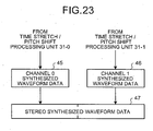
- FIG. 23 shows a data flow of the channel integration processing unit 31.
- the waveforms stored in a channel 0 synthesized waveform memory 45 and a channel 1 synthesized waveform memory 46 are rearranged in one bundle in a stereo synthesized waveform memory 47.
- the stereo-rendered audio waveforms after the band component synthesis are further processed by the phase synchronization processing unit 27.
- FIG. 11 shows details of the phase synchronization processing unit 27 of FIG. 9 in a block diagram.
- the waveform for one frame generated by the band component synthesizing units 26 is once accumulated in a buffering processing unit 33. This is because the phase synchronization processing requires the waveform of a certain length, and there are the cases where the length of one frame is not sufficient.
- the number of frames necessary for the phase synchronization processing is different as to each of the bands having undergone frequency band division. Evaluation of similarity in the phase synchronization processing described later requires periodic components included in the synthesized waveforms equivalent to several waveforms. And the length of the waveform necessary for that purpose is long as to a low-frequency band and short as to a highfrequency band.
- the number of frames is taken too long, intervals of the phase synchronization processing become wider so that the phase change becomes great enough to cause the auditory sense of discomfort due to the phase change to be perceived. It is desirable to use an adequate number of frames by considering the frequency band and auditory quality of the band. If the number of frames is within 40 msec as a time length, the discomfort due to the phase change is not so perceivable. As the wavelength becomes long on the low-frequency band, however, the number of frames of over 40 msec including the waveforms of five wavelengths or so is used.
- FIG. 16 shows memory usage of the buffering processing unit 33.
- the waveforms are outputted if the band synthesized waveforms equivalent to 3 frames are accumulated, and the synthesized waveform of the fourth frame is placed at the head of the buffering memory.
- a phase synchronization waveform generation signal is outputted simultaneously with the output of a buffered waveform so that a phase synchronization waveform is generated by a phase synchronization waveform generating unit 34 based on frequency information of the band component synthesizing units 26.
- the phase synchronization waveform is a waveform which is highly correlated with the phase condition after the waveform synthesis and is also a linear phase lead or a linear phase lag of the phase of the original waveform.
- the linear phase lead or the linear phase lag is corresponding to a lead or a lag in a time domain
- the phase synchronization waveform is equivalent to the original waveform cut out by shifting the time axis.
- a cross-fade processing unit 35 of FIG. 11 performs the cross-fade process from the buffered waveform to the phase synchronization waveform so as to allow the phase condition of the original waveform to be kept even if the time stretch/pitch shift processing is performed.
- the processing of the phase synchronization waveform generating unit 34 will be described by using a formula.
- the number of frequency components of all the channels included in the band is n.
- the amplitudes of the frequency components are a 0 , a 1 , ... to an - 1
- the phases on finishing the waveform synthesis process are ⁇ 0 , ⁇ 1 , ... ⁇ n - 1
- the instantaneous angular frequencies are ⁇ 0 , ⁇ 1 , ... ⁇ n - 1.
- the phases of the original waveforms on finishing the frame that is, the phases of the original waveforms on starting the next frame are ⁇ 0 , ⁇ 1 , ... ⁇ n - 1 .
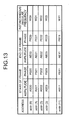
- Such frequency component information is calculated by the band component synthesizing units 26 of FIG. 9, and the information recorded on the memory as in FIG. 13 is inputted.
- a 0 , a 1 , ... to a n - 1 correspond to the amplitude AE on finishing the frame
- ⁇ 0 , ⁇ 1 , ... ⁇ n-1 correspond to the instantaneous angular frequency W
- ⁇ 0 , ⁇ 1 , ... ⁇ n-1 correspond to the phase PE on finishing the frame.
- the phases on finishing the oscillation of a cosine oscillator of FIG. 22 are referred to.
- ⁇ ⁇ , there is no phase difference and an evaluation formula is 0 as to any frequency component.
- a function F(t) is introduced, which is a function for evaluating the difference between the phase condition on finishing the waveform synthesis process and the phase condition of the original waveform in a position presumed to be shifted by "t" from the next frame starting position in the time domain.
- F(t) is the formula of Formula 2 in which ⁇ k of Formula 1 is replaced by ⁇ k + ⁇ k t .
- the phase synchronization waveform generating unit 34 of FIG. 11 acquires this t p first. To acquire this, the value of the evaluation function F(t) is acquired in the range of a time domain -t w ⁇ t ⁇ t w , and the smallest F(t) should be taken as t p . Size of t w should be the length equivalent to several wavelengths of the frequency component included in the band. If t w is too small, a point where the value of F(t) is small may not be found. Inversely, if t w is large, an error occurs in the evaluation of F(t) at a point where t is too distant from 0.
- the error occurring to the evaluation function F(t) is caused by use of the instantaneous angular frequencies ⁇ 0 , ⁇ 1 , ... ⁇ n - 1 in the formula.
- ⁇ 0 , ⁇ 1 , ... ⁇ n-1 are instantaneous values which essentially change over time.
- the formula of F(t) uses fixed values of ⁇ 0 , ⁇ 1 , ... ⁇ n - 1 , and so it is not suited to the evaluation of the phase condition because, as t goes away from 0, it becomes totally different from a primary phase condition of the original waveform. For that reason, it is important to set the value of t w at an adequate value which is not too large.
- FIG. 24 shows details of a calculation of the evaluation function F(t).
- the frequency component information analyzed by the band component synthesizing units 26 of FIG. 9 is stored in a frequency component memory of FIG. 24.
- the evaluated value is calculated in conjunction with the phases on finishing the oscillation of the cosine oscillator of the band component synthesizing units 26 and a variable t in the time domain.
- FIG. 24 it is presumed that there are n pieces of frequency components so that the values are acquired as to each of the components by using the multiplication, subtraction, cosine, and square root.
- the evaluated value is calculated by adding up these values.
- FIG. 24 represents the calculation of Formula 2 in a block diagram. The evaluated value is acquired while changing the variable t in the range of -t w to t w , and the variable t when the evaluated value becomes smallest is taken as t p .
- the phase synchronization waveform is synthesized based on the acquired t p .
- the sine or cosine oscillation is performed for each channel while performing the pitch shifting as with the time stretch/pitch shift processing units 31 of FIG. 10.
- the phase synchronization waveform is only used for the cross-fade process. Therefore, the length equivalent to several wavelengths of the frequency component included in the band is sufficient as the length for synthesizing the waveform, and the time stretch can be ignored. In this case, it is necessary to adjust the phase condition when starting the oscillation so that the phase condition at the end of the phase synchronization waveform is put in the linear phase lead or linear phase lag state by an equivalent of t p from the phase condition of the original waveform when starting the next frame.
- the phase synchronization waveform synthesized as above is outputted to the cross-fade processing unit 35 of FIG. 11.
- the cross-fade processing unit 35 performs the cross-fade process to the phase synchronization waveforms from the waveforms after the band component synthesis accumulated in the buffering processing unit 33.
- the cross-fade process is performed by mutually aligning the ends of the waveforms.
- the phase condition at the ends thereof is the same as the phase condition at the ends of the phase synchronization waveforms, which is accordingly the linear phase lead or linear phase lag state of the phase condition of the original waveforms.
- the waveforms after the cross-fade process have the phase condition equal to the original waveforms.
- the waveforms after the cross-fade process are outputted as final band waveforms.
- the t p acquired by the phase synchronization waveform generating unit 34 of FIG. 11 is outputted as the phase correction value to the band component synthesizing units 26 of FIG. 9.
- the phase correction value is outputted, the phase when starting the synthesis process of the next frame is put in the linear phase lead or linear phase lag state of the phase condition of the original waveform.
- the waveforms smoothly connecting to the waveforms after the cross-fade process are synthesized by the next frame.
- FIG. 25 A description will be given by using FIG. 25 as to the concept of the phase synchronization waveform generating unit 34 and the cross-fade processing unit 35 of FIG. 11 described so far.
- FIG. 25 two channels of the stereo audio waveform are dividedly drawn in two tiered stages, which indicates that the similarity evaluation, phase synchronization waveform generation, and cross-fade process are performed in stereo.
- a portion (a) of FIG. 25 shows the band original waveform, which is presumed undergoing twice time-stretching.
- a band synthesized waveform (b) of FIG. 25 stretched to twice is accumulated in the buffering processing unit 38 based on the band original waveform according to the processing described so far.
- the band synthesized waveform is a waveform which has the band original waveform time-stretched to twice.
- the phase relation of the frequency components at the ends has become totally different from that of the band original waveform, which is a cause of the auditory sense of discomfort due to, for example, a lack of feeling of normalcy in stereo.
- a portion (c) of FIG. 25 shows the evaluation function F(t) and an appearance of generation of the phase synchronization waveform.
- the evaluated value is calculated while changing the variable t in the range of - t w to t w , as described by using FIG. 24 based on the frequency component information analyzed on generating the band synthesized waveform and the phases on finishing the oscillation of the oscillator.
- the waveform which is the linear phase lead or lag of the end of the band original waveform on changing t is shown in the middle portion of the portion (c) of FIG. 25.
- the length of the waveform synthesized in this case is a length equivalent to two wavelengths of the frequency component included in the band.
- a portion (d) of FIG. 25 shows the waveform after the cross-fade process.
- the cross-fade process is performed by aligning the end of the band synthesized waveform of the portion (b) of FIG. 25 and the end of the phase synchronization waveform synthesized in the portion (c) of FIG. 25.
- the end of the waveform after the cross-fade process has the same value as the end of the phase synchronization waveform, which is accordingly the linear phase lead or lag state of the band original waveform.
- FIG. 26 shows details of the cross-fade process.
- the buffering memory has frame synthesized waveforms accumulated therein by the buffering processing unit 33 of FIG. 11.
- the phase synchronization waveform is generated by the phase synchronization waveform generating unit 34.
- the cross-fade process is started from a point of 1 - l p on the band synthesized waveform so as to align the ends of the two waveforms.
- the cross-fade process performs the rate calculation and multiplication of each waveform as to each sample point to output the sum of the values after the multiplication.
- the rate calculation of FIG. 26 shows an example of a cross-fade by linear interpolation.
- the waveform before 1 - l p is stored as-is as the output waveform in the output waveform memory.
- the above processing is performed to each band, and a band waveform output is added to acquire a final audio output waveform.
- the fourth embodiment has described the example of implementing the waveform processing by performing the band division on the audio input waveform.
- the same waveform processing as described in the fourth embodiment can be realized by using the means disclosed in claims 7 and 9 which do not perform the band division on the audio input waveform.
- the frequency band dividing unit 24, the band component synthesizing unit (band 1) 26-1 to the band component synthesizing unit (band 5) 26-5 and the phase synchronization processing unit (band 1) 27-1 to the phase synchronization processing unit (band 5) 27-5 are deleted, and the audio input waveform 23 is directly inputted to the band component synthesizing unit (band 0) 26-0 so as to implement the same waveform processing as described in the fourth embodiment.
- FIG. 20 shows a flowchart of the computer program.
- the input waveform data is read (step S1), and the frequency band dividing process (step S2) which is the same as that of the frequency band dividing unit 24 of FIG. 9 is performed so as to output the waveform of each band.
- This process is composed of an instruction group such as multiplications and additions for realizing the band-pass filter or an instruction group for executing the FFT in the case of realizing the band division by the Fourier transform.
- step S3 an analytical process is performed as to the instantaneous amplitude, angular frequency, and phases of the band waveform data having undergone the frequency band division (step S3).
- This process is a part equivalent to the frequency analysis units 30-0 to 30-1 of FIG. 10, and is composed of an instruction group for executing the FFT and instruction groups of the square roots for calculating the amplitude, arctans for calculating the phases, and the like.
- the waveform synthesis process (step S4) is executed based on the analyzed data.
- This process is the same process as that of the time stretch/pitch shift processing units 31-0 to 31-1 of FIG. 10. It is composed of instruction groups such as the cosine functions for playing a role of an oscillator and multiplications for multiplying the amplitudes, where the time stretched and/or pitch-shifted waveform is synthesized.
- step S5 it is determined whether or not the length of the synthesized waveform has reached the length necessary for the phase synchronization processing (step S5). In the case where the necessary length has not been reached, the procedure returns to the step S1 to repeat the process until the necessary length is reached while accumulating the synthesized waveforms in the memory. In the case where the necessary length has been reached, the procedure moves on to the next step. This process is the same process as that of the buffering processing unit 33 of FIG. 11.
- phase synchronization processing (step S6) is performed to the synthesized waveform.
- This processing is equivalent to the processing of the phase synchronization waveform generating unit 34 and the cross-fade processing unit 35 of FIG. 11.
- This processing is composed of an instruction group of subtractions, multiplications, cosines, and square roots for executing a phase evaluation function and the like and an instruction group of multiplications and additions for performing the cross-fade process.
- step S2 to the step S6 is performed as to each of the bands having undergone the band division, and the output waveform data of each band is added up to execute the output waveform data writing (step S7).
- An instruction of addition is used to add up the output waveform data of the bands.
- step S8 it is determined whether or not the processing has been finished as to the entire input waveform. If the processing has not been finished, the procedure returns to the step S1 to repeat the processing. If the processing has been finished as to the entire input waveform, the processing is finished.
- the frequency analysis and the synthesis process of the audio signal are performed as to each of the bands divided into multiple frequency bands to evaluate the similarity between the original waveform and the waveform after the synthesis process as to each band.
- the cross-fade process is performed at the locations of high similarity between the waveform after the synthesis process and the band original waveform so that the phase change occurring on the waveform synthesis can be reset.
- the similarity between the original waveform and the waveform after the synthesis process is evaluated by regarding the audio waveform as-is as one band without performing the band division.
- the cross-fade process is performed at the locations of high similarity between the waveform after the synthesis process and the original waveform so that the phase change occurring on the waveform synthesis can be reset.
- the audio waveform processing method described in one of claims 3 and 4 can be performed by a commercially available audio processing program for a personal computer so that vocoder-method audio processing of high quality can be realized at even lower prices.
- the frequency analysis and the synthesis process are performed as to each of the bands of the audio signal divided into multiple frequency bands.
- the phase condition after the synthesis process of each band is compared with the phase condition of the original waveform to generate the waveform which is highly correlated with the phase condition after the synthesis process and is a linear phase lead or a linear phase lag of the original waveform as a phase synchronization waveform.
- the cross-fade process is performed to turn the waveform after the synthesis process to a movement synchronization waveform so that the phase change occurring on the waveform synthesis can be reset.
- the audio waveform is processed by regarding it as-is as one band without performing the band division in the frequency band division of the device according to claim 6.
- the audio waveform processing method described in one of claims 8 and 9 can be performed by a commercially available audio processing program for a personal computer so that vocoder-method audio processing of high quality can be realized at even lower prices.
- a distance on a complex-number plane between the waveforms is used as an evaluation function for evaluating the difference between the phase condition after the waveform synthesis process of each band and the phase condition of the original waveform of each band.
- the effect of using the audio waveform processing device, method, and program of the present invention is that, whether the audio input waveform is monaural or stereo, the phase change invariably occurring in the conventional vocoder method is reduced through the entire waveform so that the time stretch and pitch shift processing of high quality can be realized.
Landscapes
- Engineering & Computer Science (AREA)
- Signal Processing (AREA)
- Physics & Mathematics (AREA)
- Human Computer Interaction (AREA)
- Health & Medical Sciences (AREA)
- Audiology, Speech & Language Pathology (AREA)
- Quality & Reliability (AREA)
- Computational Linguistics (AREA)
- Acoustics & Sound (AREA)
- Multimedia (AREA)
- Spectroscopy & Molecular Physics (AREA)
- Electrophonic Musical Instruments (AREA)
- Stereophonic System (AREA)
- Signal Processing For Digital Recording And Reproducing (AREA)
Applications Claiming Priority (2)
| Application Number | Priority Date | Filing Date | Title |
|---|---|---|---|
| JP2004382895 | 2004-12-27 | ||
| PCT/JP2005/023828 WO2006070768A1 (ja) | 2004-12-27 | 2005-12-26 | オーディオ波形処理装置、方式およびプログラム |
Publications (3)
| Publication Number | Publication Date |
|---|---|
| EP1840871A1 true EP1840871A1 (de) | 2007-10-03 |
| EP1840871A4 EP1840871A4 (de) | 2009-04-29 |
| EP1840871B1 EP1840871B1 (de) | 2017-07-12 |
Family
ID=36614885
Family Applications (1)
| Application Number | Title | Priority Date | Filing Date |
|---|---|---|---|
| EP05842258.5A Expired - Lifetime EP1840871B1 (de) | 2004-12-27 | 2005-12-26 | Vorrichtung, verfahren und programm zur audiowellenformverarbeitung |
Country Status (5)
| Country | Link |
|---|---|
| US (1) | US8296143B2 (de) |
| EP (1) | EP1840871B1 (de) |
| JP (1) | JP4031813B2 (de) |
| KR (1) | KR101286168B1 (de) |
| WO (1) | WO2006070768A1 (de) |
Families Citing this family (12)
| Publication number | Priority date | Publication date | Assignee | Title |
|---|---|---|---|---|
| WO2007036824A2 (en) * | 2005-09-30 | 2007-04-05 | Koninklijke Philips Electronics N.V. | Method and apparatus for processing audio for playback |
| JP4827661B2 (ja) * | 2006-08-30 | 2011-11-30 | 富士通株式会社 | 信号処理方法及び装置 |
| JP5535241B2 (ja) * | 2009-12-28 | 2014-07-02 | 三菱電機株式会社 | 音声信号復元装置および音声信号復元方法 |
| US8762158B2 (en) * | 2010-08-06 | 2014-06-24 | Samsung Electronics Co., Ltd. | Decoding method and decoding apparatus therefor |
| WO2013149188A1 (en) | 2012-03-29 | 2013-10-03 | Smule, Inc. | Automatic conversion of speech into song, rap or other audible expression having target meter or rhythm |
| JP2014041240A (ja) * | 2012-08-22 | 2014-03-06 | Pioneer Electronic Corp | タイムスケーリング方法、ピッチシフト方法、オーディオデータ処理装置およびプログラム |
| JP6428256B2 (ja) * | 2014-12-25 | 2018-11-28 | ヤマハ株式会社 | 音声処理装置 |
| EP3392884A1 (de) * | 2017-04-21 | 2018-10-24 | audEERING GmbH | Verfahren zur automatischen inferenz des affektischen zustands und system zur automatischen inferenz des affektischen zustands |
| US10887709B1 (en) * | 2019-09-25 | 2021-01-05 | Amazon Technologies, Inc. | Aligned beam merger |
| JP7488703B2 (ja) * | 2020-06-18 | 2024-05-22 | フォルシアクラリオン・エレクトロニクス株式会社 | 信号処理装置及び信号処理プログラム |
| US12401942B1 (en) | 2023-05-25 | 2025-08-26 | Amazon Technologies, Inc. | Group beam selection and beam merging |
| US12531048B1 (en) | 2023-09-05 | 2026-01-20 | Amazon Technologies, Inc. | Step-size control for multi-channel acoustic echo canceller |
Family Cites Families (33)
| Publication number | Priority date | Publication date | Assignee | Title |
|---|---|---|---|---|
| JPS5650398A (en) * | 1979-10-01 | 1981-05-07 | Hitachi Ltd | Sound synthesizer |
| EP0527527B1 (de) * | 1991-08-09 | 1999-01-20 | Koninklijke Philips Electronics N.V. | Verfahren und Apparat zur Handhabung von Höhe und Dauer eines physikalischen Audiosignals |
| JP3218679B2 (ja) | 1992-04-15 | 2001-10-15 | ソニー株式会社 | 高能率符号化方法 |
| US5386493A (en) * | 1992-09-25 | 1995-01-31 | Apple Computer, Inc. | Apparatus and method for playing back audio at faster or slower rates without pitch distortion |
| JP3296648B2 (ja) * | 1993-11-30 | 2002-07-02 | 三洋電機株式会社 | ディジタル音程変換における不連続点の改善処理方法およびその装置 |
| US5920842A (en) * | 1994-10-12 | 1999-07-06 | Pixel Instruments | Signal synchronization |
| US5842172A (en) * | 1995-04-21 | 1998-11-24 | Tensortech Corporation | Method and apparatus for modifying the play time of digital audio tracks |
| SG65729A1 (en) * | 1997-01-31 | 1999-06-22 | Yamaha Corp | Tone generating device and method using a time stretch/compression control technique |
| JP3017715B2 (ja) * | 1997-10-31 | 2000-03-13 | 松下電器産業株式会社 | 音声再生装置 |
| JP3949828B2 (ja) | 1998-10-15 | 2007-07-25 | ヤマハ株式会社 | 音声変換装置及び音声変換方法 |
| JP3540609B2 (ja) | 1998-06-15 | 2004-07-07 | ヤマハ株式会社 | 音声変換装置及び音声変換方法 |
| JP3502265B2 (ja) | 1998-06-15 | 2004-03-02 | ヤマハ株式会社 | 音声分析装置、音声分析方法、および音声分析プログラムを記録した記録媒体 |
| TW430778B (en) * | 1998-06-15 | 2001-04-21 | Yamaha Corp | Voice converter with extraction and modification of attribute data |
| JP3294192B2 (ja) | 1998-06-22 | 2002-06-24 | ヤマハ株式会社 | 音声変換装置及び音声変換方法 |
| JP3706249B2 (ja) | 1998-06-16 | 2005-10-12 | ヤマハ株式会社 | 音声変換装置、音声変換方法、および音声変換プログラムを記録した記録媒体 |
| JP3540159B2 (ja) | 1998-06-18 | 2004-07-07 | ヤマハ株式会社 | 音声変換装置及び音声変換方法 |
| JP3644263B2 (ja) * | 1998-07-31 | 2005-04-27 | ヤマハ株式会社 | 波形形成装置及び方法 |
| JP3430974B2 (ja) * | 1999-06-22 | 2003-07-28 | ヤマハ株式会社 | ステレオ信号の時間軸圧伸方法及び装置 |
| JP2001084000A (ja) * | 1999-09-08 | 2001-03-30 | Roland Corp | 波形再生装置 |
| JP4344438B2 (ja) | 1999-10-22 | 2009-10-14 | ローランド株式会社 | オーディオ信号波形処理装置 |
| TW525146B (en) * | 2000-09-22 | 2003-03-21 | Matsushita Electric Industrial Co Ltd | Method and apparatus for shifting pitch of acoustic signals |
| JP4067762B2 (ja) * | 2000-12-28 | 2008-03-26 | ヤマハ株式会社 | 歌唱合成装置 |
| US20020116178A1 (en) * | 2001-04-13 | 2002-08-22 | Crockett Brett G. | High quality time-scaling and pitch-scaling of audio signals |
| JP4152192B2 (ja) | 2001-04-13 | 2008-09-17 | ドルビー・ラボラトリーズ・ライセンシング・コーポレーション | オーディオ信号の高品質タイムスケーリング及びピッチスケーリング |
| US7610205B2 (en) * | 2002-02-12 | 2009-10-27 | Dolby Laboratories Licensing Corporation | High quality time-scaling and pitch-scaling of audio signals |
| JP2003022100A (ja) | 2001-07-09 | 2003-01-24 | Yamaha Corp | 雑音除去方法、雑音除去装置およびプログラム |
| EP1304680A3 (de) * | 2001-09-13 | 2004-03-03 | Yamaha Corporation | Vorrichtung und Verfahren zur synchronisierten Synthesierung von verschiedenen Wellenformen |
| DE10148351B4 (de) * | 2001-09-29 | 2007-06-21 | Grundig Multimedia B.V. | Verfahren und Vorrichtung zur Auswahl eines Klangalgorithmus |
| EP1446796A1 (de) | 2001-10-26 | 2004-08-18 | Koninklijke Philips Electronics N.V. | Verfolgung von sinus-parametern in einem audiokodierer |
| US7764758B2 (en) * | 2003-01-30 | 2010-07-27 | Lsi Corporation | Apparatus and/or method for variable data rate conversion |
| US7521623B2 (en) * | 2004-11-24 | 2009-04-21 | Apple Inc. | Music synchronization arrangement |
| US20040254660A1 (en) * | 2003-05-28 | 2004-12-16 | Alan Seefeldt | Method and device to process digital media streams |
| US7571104B2 (en) * | 2005-05-26 | 2009-08-04 | Qnx Software Systems (Wavemakers), Inc. | Dynamic real-time cross-fading of voice prompts |
-
2005
- 2005-12-26 JP JP2006550774A patent/JP4031813B2/ja not_active Expired - Lifetime
- 2005-12-26 WO PCT/JP2005/023828 patent/WO2006070768A1/ja not_active Ceased
- 2005-12-26 EP EP05842258.5A patent/EP1840871B1/de not_active Expired - Lifetime
- 2005-12-26 KR KR1020077017186A patent/KR101286168B1/ko not_active Expired - Lifetime
- 2005-12-26 US US11/722,966 patent/US8296143B2/en active Active
Also Published As
| Publication number | Publication date |
|---|---|
| US20080033726A1 (en) | 2008-02-07 |
| KR20070100334A (ko) | 2007-10-10 |
| US8296143B2 (en) | 2012-10-23 |
| JP4031813B2 (ja) | 2008-01-09 |
| WO2006070768A1 (ja) | 2006-07-06 |
| JPWO2006070768A1 (ja) | 2008-08-07 |
| KR101286168B1 (ko) | 2013-07-15 |
| EP1840871B1 (de) | 2017-07-12 |
| EP1840871A4 (de) | 2009-04-29 |
Similar Documents
| Publication | Publication Date | Title |
|---|---|---|
| JP3528258B2 (ja) | 符号化音声信号の復号化方法及び装置 | |
| EP2401740B1 (de) | Vorrichtung und verfahren zum bestimmen mehrerer lokal-schwerpunktfrequenzen eines spektrums eines audiosignals | |
| EP1840871B1 (de) | Vorrichtung, verfahren und programm zur audiowellenformverarbeitung | |
| JP4293712B2 (ja) | オーディオ波形再生装置 | |
| JP4076887B2 (ja) | ボコーダ装置 | |
| JP4170458B2 (ja) | 波形信号の時間軸圧縮伸長装置 | |
| US8492639B2 (en) | Audio processing apparatus and method | |
| CN1266675C (zh) | 语音速率变换装置及方法 | |
| JP4455701B2 (ja) | 音声信号処理装置および音声信号処理方法 | |
| JP5552794B2 (ja) | 音響信号の符号化方法および装置 | |
| Kraft et al. | Improved PVSOLA time-stretching and pitch-shifting for polyphonic audio | |
| Hanna et al. | Time scale modification of noises using a spectral and statistical model | |
| JP4245114B2 (ja) | 音色制御装置 | |
| JP4170459B2 (ja) | 波形信号の時間軸圧縮伸長装置 | |
| RU2800676C1 (ru) | Усовершенствованное гармоническое преобразование на основе блока поддиапазонов | |
| EP3447767A1 (de) | Verfahren zur phasenkorrektur in einem phasenvocoder und vorrichtung | |
| JP3592617B2 (ja) | 音声合成方法、その装置及びそのプログラム記録媒体 | |
| JP4226164B2 (ja) | 波形信号の時間軸圧縮伸長装置 | |
| Kreutzer et al. | A parametric model for spectral sound synthesis of musical sounds | |
| JP5609280B2 (ja) | 音響信号の符号化方法および装置 | |
| JP5533021B2 (ja) | 音響信号の符号化方法および装置 | |
| JP2003241777A (ja) | 楽音のフォルマント抽出方法、記録媒体及び楽音のフォルマント抽出装置 | |
| JP2008096844A (ja) | 自動採譜装置及び方法 | |
| JP2000010600A (ja) | 音声変換装置および音声変換方法 | |
| Trevorrow | Investigation of digital audio manipulation methods |
Legal Events
| Date | Code | Title | Description |
|---|---|---|---|
| PUAI | Public reference made under article 153(3) epc to a published international application that has entered the european phase |
Free format text: ORIGINAL CODE: 0009012 |
|
| 17P | Request for examination filed |
Effective date: 20070716 |
|
| AK | Designated contracting states |
Kind code of ref document: A1 Designated state(s): DE GB |
|
| DAX | Request for extension of the european patent (deleted) | ||
| RBV | Designated contracting states (corrected) |
Designated state(s): DE GB |
|
| A4 | Supplementary search report drawn up and despatched |
Effective date: 20090401 |
|
| RIC1 | Information provided on ipc code assigned before grant |
Ipc: G10L 21/04 20060101AFI20090326BHEP |
|
| 17Q | First examination report despatched |
Effective date: 20100706 |
|
| REG | Reference to a national code |
Ref country code: DE Ref legal event code: R079 Ref document number: 602005052328 Country of ref document: DE Free format text: PREVIOUS MAIN CLASS: G10L0013060000 Ipc: G10L0019020000 |
|
| GRAP | Despatch of communication of intention to grant a patent |
Free format text: ORIGINAL CODE: EPIDOSNIGR1 |
|
| RIC1 | Information provided on ipc code assigned before grant |
Ipc: G10L 21/04 20130101ALI20170207BHEP Ipc: G10L 19/02 20130101AFI20170207BHEP |
|
| INTG | Intention to grant announced |
Effective date: 20170306 |
|
| RIN1 | Information on inventor provided before grant (corrected) |
Inventor name: KUDOH, TAKUMA |
|
| GRAS | Grant fee paid |
Free format text: ORIGINAL CODE: EPIDOSNIGR3 |
|
| GRAA | (expected) grant |
Free format text: ORIGINAL CODE: 0009210 |
|
| AK | Designated contracting states |
Kind code of ref document: B1 Designated state(s): DE GB |
|
| REG | Reference to a national code |
Ref country code: GB Ref legal event code: FG4D |
|
| REG | Reference to a national code |
Ref country code: DE Ref legal event code: R096 Ref document number: 602005052328 Country of ref document: DE |
|
| REG | Reference to a national code |
Ref country code: DE Ref legal event code: R097 Ref document number: 602005052328 Country of ref document: DE |
|
| PLBE | No opposition filed within time limit |
Free format text: ORIGINAL CODE: 0009261 |
|
| STAA | Information on the status of an ep patent application or granted ep patent |
Free format text: STATUS: NO OPPOSITION FILED WITHIN TIME LIMIT |
|
| 26N | No opposition filed |
Effective date: 20180413 |
|
| PGFP | Annual fee paid to national office [announced via postgrant information from national office to epo] |
Ref country code: GB Payment date: 20241212 Year of fee payment: 20 |
|
| PGFP | Annual fee paid to national office [announced via postgrant information from national office to epo] |
Ref country code: DE Payment date: 20241217 Year of fee payment: 20 |
|
| REG | Reference to a national code |
Ref country code: DE Ref legal event code: R071 Ref document number: 602005052328 Country of ref document: DE |
|
| REG | Reference to a national code |
Ref country code: GB Ref legal event code: PE20 Expiry date: 20251225 |