EP1841069B1 - Appareil de détection d'objet dans une zone de détection d'un dispositif de capteur et son procédé de fonctionnement - Google Patents
Appareil de détection d'objet dans une zone de détection d'un dispositif de capteur et son procédé de fonctionnement Download PDFInfo
- Publication number
- EP1841069B1 EP1841069B1 EP20070006120 EP07006120A EP1841069B1 EP 1841069 B1 EP1841069 B1 EP 1841069B1 EP 20070006120 EP20070006120 EP 20070006120 EP 07006120 A EP07006120 A EP 07006120A EP 1841069 B1 EP1841069 B1 EP 1841069B1
- Authority
- EP
- European Patent Office
- Prior art keywords
- electromagnetic field
- sensor electrode
- opening region
- detecting
- antenna
- Prior art date
- Legal status (The legal status is an assumption and is not a legal conclusion. Google has not performed a legal analysis and makes no representation as to the accuracy of the status listed.)
- Ceased
Links
- 238000000034 method Methods 0.000 title claims description 30
- 238000001514 detection method Methods 0.000 title description 8
- 230000005672 electromagnetic field Effects 0.000 claims description 42
- 230000005684 electric field Effects 0.000 claims description 11
- 230000003213 activating effect Effects 0.000 claims description 4
- 230000008859 change Effects 0.000 description 8
- 239000003990 capacitor Substances 0.000 description 5
- 230000008569 process Effects 0.000 description 4
- 238000013461 design Methods 0.000 description 3
- 238000011156 evaluation Methods 0.000 description 3
- 239000003999 initiator Substances 0.000 description 3
- 230000035515 penetration Effects 0.000 description 3
- 238000013459 approach Methods 0.000 description 2
- 230000008901 benefit Effects 0.000 description 2
- 239000004020 conductor Substances 0.000 description 2
- 230000009849 deactivation Effects 0.000 description 2
- 238000003780 insertion Methods 0.000 description 2
- 230000037431 insertion Effects 0.000 description 2
- 239000000463 material Substances 0.000 description 2
- 238000012544 monitoring process Methods 0.000 description 2
- 230000010355 oscillation Effects 0.000 description 2
- 230000003534 oscillatory effect Effects 0.000 description 2
- 238000012545 processing Methods 0.000 description 2
- 239000012190 activator Substances 0.000 description 1
- 238000004458 analytical method Methods 0.000 description 1
- 230000000903 blocking effect Effects 0.000 description 1
- 238000012512 characterization method Methods 0.000 description 1
- 239000003795 chemical substances by application Substances 0.000 description 1
- 238000010276 construction Methods 0.000 description 1
- 230000001419 dependent effect Effects 0.000 description 1
- 238000011161 development Methods 0.000 description 1
- 230000000694 effects Effects 0.000 description 1
- 230000007613 environmental effect Effects 0.000 description 1
- 230000001939 inductive effect Effects 0.000 description 1
- 238000011017 operating method Methods 0.000 description 1
- 230000002093 peripheral effect Effects 0.000 description 1
- 230000009467 reduction Effects 0.000 description 1
- 230000035945 sensitivity Effects 0.000 description 1
- 238000012360 testing method Methods 0.000 description 1
- 230000000007 visual effect Effects 0.000 description 1
Images
Classifications
-
- H—ELECTRICITY
- H03—ELECTRONIC CIRCUITRY
- H03K—PULSE TECHNIQUE
- H03K17/00—Electronic switching or gating, i.e. not by contact-making and –breaking
- H03K17/94—Electronic switching or gating, i.e. not by contact-making and –breaking characterised by the way in which the control signals are generated
- H03K17/945—Proximity switches
- H03K17/955—Proximity switches using a capacitive detector
-
- H—ELECTRICITY
- H03—ELECTRONIC CIRCUITRY
- H03K—PULSE TECHNIQUE
- H03K17/00—Electronic switching or gating, i.e. not by contact-making and –breaking
- H03K17/94—Electronic switching or gating, i.e. not by contact-making and –breaking characterised by the way in which the control signals are generated
- H03K17/945—Proximity switches
- H03K17/95—Proximity switches using a magnetic detector
- H03K17/9502—Measures for increasing reliability
-
- E—FIXED CONSTRUCTIONS
- E05—LOCKS; KEYS; WINDOW OR DOOR FITTINGS; SAFES
- E05Y—INDEXING SCHEME ASSOCIATED WITH SUBCLASSES E05D AND E05F, RELATING TO CONSTRUCTION ELEMENTS, ELECTRIC CONTROL, POWER SUPPLY, POWER SIGNAL OR TRANSMISSION, USER INTERFACES, MOUNTING OR COUPLING, DETAILS, ACCESSORIES, AUXILIARY OPERATIONS NOT OTHERWISE PROVIDED FOR, APPLICATION THEREOF
- E05Y2800/00—Details, accessories and auxiliary operations not otherwise provided for
- E05Y2800/40—Physical or chemical protection
Definitions
- the present invention relates to a method for operating an apparatus for detecting an obstacle in the opening area of a closing device in a time interval. Furthermore, an apparatus for detecting an obstacle in the opening region of a closing device is proposed. Such apparatus and methods are used in particular in connection with a jamming protection in moving components of vehicles.
- a protection device in particular the trapping of, for example, human body parts between moving components of a motor vehicle to be prevented.
- the known devices can be subdivided into directly or indirectly operating anti-jamming devices.
- a direct anti-pinch device is understood to mean devices or systems which have sensors which directly detect an obstacle and transmit a corresponding signal to an electric motor (for example, driving a window pane).
- an indirectly operating anti-jamming device the load acting on the electric motor for moving the window pane is detected and the presence of an obstacle is indirectly determined by the processing of the specific parameters of the electric motor.
- tactile and non-contact anti-jamming devices are distinguished.
- compressible materials are provided, which are designed, for example, with a plurality of spaced-apart, electrically conductive regions, the conductive regions being pressed against one another as a result of physical contact. Due to this change in position and / or an electrical contact of these areas, a corresponding Signal to be detected.
- non-contact anti-pinch devices it is known to provide an electrical conductor in the vicinity of the opening area to be monitored, which constitutes a sensor electrode which generates an electric or electromagnetic field in the opening area. If an object of this sensor electrode now approaches, the change in the surrounding electrical or electromagnetic field can be detected on the basis of capacitively and / or inductively acting sensor elements.
- Such a combined device is for example from the DE 103 10 066 B3 out. With such a combined device can be achieved that in case of incorrect operation of non-contact anti-pinch due to a disturbed electromagnetic field nevertheless a tactile anti-trap protection for body parts or other items is guaranteed.
- the DE 198 03 643 A1 describes a device for a non-contact sensor detection, in which influences due to interference due to external electromagnetic fields detected by another sensor and taken into account in the evaluation.
- the object of the present invention is to at least partially solve the problems described with reference to the prior art.
- a perfect operation of sensor devices is to be ensured, which should determine the penetration of an object into the associated detection area.
- a method and an apparatus for realizing an anti-trap protection are to be specified, whereby a reliable interpretation of the actual situation during the closing process is ensured.
- the apparatus should be as simple as possible and space-saving, for example, be mounted in a vehicle. With the method for operating such an apparatus, in particular plausibility checks of the detected signals are to be made possible, so that unwanted false triggering of the anti-jamming protection is avoided, especially in connection with capacitive anti-jamming devices in electromagnetic interference fields.
- the method proposed here can preferably be used in connection with the detection of objects (body parts, objects, etc.) in the detection area of a sensor device for, for example, parking guidance systems, drive guidance systems, anti-theft devices, personal identification systems, access identification systems, door handle actuation devices and the like.
- a sensor device for, for example, parking guidance systems, drive guidance systems, anti-theft devices, personal identification systems, access identification systems, door handle actuation devices and the like.
- even (capacitively operating) sensor devices which can not be adequately shielded against external electromagnetic fields and / or which react so sensitively to these external fields that even backup capacitors are insufficient to compensate for the negative influence on the measured value acquisition, can nevertheless be operated safely because they are otherwise disabled.
- Even if the method according to the invention is subsequently explained in many cases only in the light of anti-pinch protection, its application in the above sense is likewise advantageous and correspondingly to be transferred.
- the method mentioned here for detecting an obstacle in the opening region of a closing device finds particular application in the realization of an anti-jamming protection in the opening area of sunroofs, side doors, tailgates, side windows or similar closing devices of a vehicle.
- an electrical or electromagnetic field (so-called measuring field) is now first generated with this apparatus, so that a contact-free anti-pinch protection is realized.
- the detection of a measured value relates, in particular, to the determination of a changing inductance or capacitance of the sensor electrode and / or other electrical or electronic components of the apparatus cooperating therewith, for which purpose it is also possible to fall back on parameters based thereon, such as frequencies, etc.
- activated electrical or electromagnetic field can be detected without contact, the penetration of an obstacle in the opening area without contact, which can be interrupted for identifying a potential pinching situations, in particular the closing operation of the closing device or transferred to another operating mode.
- step b it is intermittently determined during the closing operation or the predeterminable time interval which external electromagnetic fields exist in or in the vicinity of the opening area of the closing device (cf step b). ).
- at least one antenna is used which detects a, for the external electromagnetic field characteristic, disturbance.
- step b) becomes temporarily disabled the self-generated field of view, so that an independent determination of the external electromagnetic field can be made.
- this actually detected disturbance variable is compared with a reference variable.
- the reference variable regularly represents a characteristic value or a characteristic value range with which the limits of a faultlessly working non-contact anti-jamming device in the presence of external electromagnetic fields are determined.
- step d) now an abort criterion for the implementation of non-contact anti-trap protection is given. Accordingly, this is to be deactivated regularly when the time interval has expired, so a perfect operation of non-contact anti-trap protection was guaranteed.
- the time interval extends in particular over the period in which the closing device is open, but in any case over the period of the closing process itself.
- a termination of non-contact anti-trap protection is preferably realized just when the disturbance of the external electromagnetic field of the reference size deviates significantly.
- a "significant" deviation is present in particular when the disturbance has left a control range of the reference variable, in which case (possibly as a function of the accuracy of the sensors and circuit elements used) the exceeding of additional tolerance thresholds and / or a repetition of the deviation within a short period of time can be required.
- the non-contact anti-trap now does not work in the expected exact way and the risk of misinterpretation is increased.
- the non-contact anti-trap protection is disabled, if necessary, only a different mode of operation of the locking device can be adjusted.
- a protection against incorrect insertion of non-contact anti-trap protection is given locally disturbing external electromagnetic fields.
- the advantage of this method is, in particular, that a faulty insertion of the anti-trap protection, which can still occur in the known systems, be ruled out from the outset, that is, a faulty interpreted pinching situation is avoided by this system.
- the results of this method, in particular the disturbance can be used to pass on, for example, an audible and / or visual feedback to the user of the vehicle.
- the detection of an external disturbing electromagnetic field could be used to change the operation of the closure device, so that a suitable for example for the tactile anti-trap protection method is selected.
- step b) the at least one sensor electrode of the apparatus is operated intermittently as an antenna, wherein before performing step b) the electric or electromagnetic field is deactivated and then steps a) to c) are repeated until the time interval expires or the condition in step d) is met.
- this method it is ensured, in particular, that the self-generated electromagnetic field for contact-free anti-jamming protection and the external electromagnetic field are not present simultaneously for performing step b).
- step b) is carried out in concrete and / or variable time intervals, the frequency in particular being able to depend on the time interval in which contact-free anti-jamming protection is to be implemented or the movement behavior of the closing device.
- step a) a check of the external electromagnetic field for the first time by means of steps b) and c) is prompted to determine whether ever activating the non-contact anti-trap protection under the prevailing environmental conditions in terms of the presence of external electromagnetic fields makes sense.
- step a) comprises the construction of an alternating electromagnetic field, wherein the sensor electrode cooperates with a resonant circuit.
- a capacitive or inductive base electric sensors can be used, which contain a non-contact initiator having, for example, a high-frequency oscillator in a blocking circuit with an activated LC or RC resonant circuit. If it is an LC initiator, then the inductance of the LC resonant circuit is designed as a coil with directed high-frequency field.
- the sensor electrode is part of the capacitor of the RC resonant circuit (preferred embodiment) whose capacitance is able to change when an object with a sufficiently large dielectric constant approaches the sensor electrode, whereby the RC Resonant circuit too Vibrations is excited or tearing off vibrations and the change of the oscillation amplitude can be evaluated eg in a downstream envelope modulator.
- Switches with such sensors have in particular the property that the distance depends on the material properties under the nature of the body to be detected.
- the change in the capacity of the opening area causes a change in the frequency, which can then be evaluated (recording a measured value).
- the measured value is a current natural frequency of the oscillatory circuit.
- a capacitively operating sensor electrode is preferably used.
- step b) is initiated after a predetermined period of time or a deviation of the expected measured value.
- the checking of external electromagnetic fields is rigid, ie. H. can be made independent of the operation of the locking device or the non-contact anti-trap protection. It is also possible that the operation of the locking device or the contactless anti-trap protection can be included, so that in the presence of certain operating situations (for example, in the identification of a potential pinching situation) the disturbance is determined. Of course, combined methods are possible.
- step b) is carried out for a test duration of a few milliseconds, in particular not more than 10 milliseconds. This particularly applies to the case when the sensor electrode is used as an antenna. In this way, it is ensured that the contact-free anti-jamming protection is deactivated only for a very short period of time, during which time interval the closing device can be stopped or slowed down, if necessary, in order to avoid the risk of a sudden jamming event.
- the disturbance is a frequency of the external electromagnetic field.
- a tactile sensor unit in the vicinity of the opening area is additionally activated at least during the time interval after the termination of step a).
- substantially the entire peripheral area of the opening area to be monitored is monitored by the tactile sensor units.
- an apparatus for detecting an obstacle in the opening area of a closing device which comprises the elements contained in claim 7, is also proposed.
- the sensor electrode preferably has a capacitive acting sensor electrode.
- a circuit arrangement is provided, so that the sensor electrode can be operated temporarily as part of an electrical oscillating circuit and temporarily as an antenna.
- the sensor electrode is to be operated as part of a capacitor of an RC resonant circuit in the former period.
- the sensor electrode can also interact with a (or the same) resonant circuit, in particular in the manner of a so-called dipole antenna, wherein a receiving antenna is formed.
- a tactile sensor unit is provided in the vicinity of the opening area.
- several tactile sensor units can be provided. This ensures that in the event of deactivation of non-contact anti-trap protection nevertheless provision is made for a trapping case. These then take over the monitoring function of the opening area as tactile anti-jamming protection.
- the antenna is connected via an A / D converter with a microcontroller, which detects a disturbance of the external electromagnetic field.
- the detected with the antenna analog interference are converted into digital data (analog-to-digital converter), which then processed in the microcontroller and / or stored can be.
- digital data analog-to-digital converter
- inventions of the apparatus proposed here are particularly suitable for carrying out one of the methods described above according to the invention, so that the combination of apparatus and operating method is particularly advantageous.
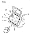
- the Fig. 1 shows partially in perspective a motor vehicle 14 with a closing device 4 in the form of a tailgate.
- the closing device 4 is opened, so that the opening area 3 can be seen.
- Around this opening area 3 around a plurality of sensor electrodes 5 are provided, so that the penetration of an obstacle 2 can be detected substantially over the entire opening area 3.
- the sensor electrodes 5 can also be partially combined with tactile sensor units 8, the sensor electrode 5 preferably having a capacitive effect.
- the apparatus 1 for detecting the obstacle 2, in this case, for example, a hand also comprises a control unit 9 for, for example, the sensor electrodes 5, which optionally can interact with a drive 15 for the closing device 4.
- one of the sensor electrodes is now designed as an antenna 6 for identifying an external electromagnetic field in the opening area 3. If, for example, the closing device 4 is closed, an electromagnetic field (so-called measuring field) is first activated by means of the sensor electrodes 5 positioned around the opening region 3, so that a measured value for providing non-contact anti-jamming protection is generated and forwarded to the control unit 9. After a predetermined period of time, the electromagnetic field is now deactivated and the sensor electrode shown below briefly operated as an antenna 6, wherein a disturbance of the external electromagnetic field in the environment 13 of the vehicle 4 near the opening area 3 is determined. This disturbance variable is optionally forwarded to the control unit 9 and processed there.
- an electromagnetic field so-called measuring field
- the electromagnetic field is now deactivated and the sensor electrode shown below briefly operated as an antenna 6, wherein a disturbance of the external electromagnetic field in the environment 13 of the vehicle 4 near the opening area 3 is determined. This disturbance variable is optionally forwarded to the control unit 9 and processed there.
- the electromagnetic field is activated and the closing process is continued.
- a short-term plausibility check is carried out in such a way that the sensor electrode is again operated as antenna 6. This indicates a redundant system.
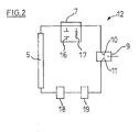
- Fig. 2 schematically illustrates a possible structure for a circuit arrangement 12 for operating the sensor electrode 5 intermittently as an antenna.
- the sensor electrode 5 is a capacitive component 5 for a resonant circuit 7, which is designed with a capacitor 16 and a coil 17.
- the control of the sensor electrode 5 is carried out with the activating means 10 and deactivating means 11 of the control unit 9.
- the disturbance variables thus generated are fed to an A / D converter 18 and subsequently to a microcontroller 19, the position of which is shown here purely schematically in front of the control unit 9.
- the sensor electrode 5 can be listed in several parts, and thus in particular also comprise a plurality of components for realizing a capacitive sensor electrode 5 or an antenna. Also, the connecting lines between the components are not necessarily separate electrical conductors, these should only let each recognize which parts interact with each other.
- the detection of a potentially non-contact, capacitive, anti-pinch protection influencing electric field is achieved in a simple manner.
- This information can be used, for example, to acoustically and / or optically inform the users in the environment that, under certain circumstances, faultless contact-free anti-jamming protection can not be guaranteed. This can lead to the deactivation of non-contact anti-pinch protection.
- the information regarding the external electromagnetic field may also be provided to other components on the vehicle which are sensitive to the presence of electromagnetic fields.
Landscapes
- Power-Operated Mechanisms For Wings (AREA)
Claims (9)
- Procédé pour le fonctionnement d'un appareil (1) pour la reconnaissance d'un obstacle (2) dans le champ d'ouverture (3) d'un dispositif de fermeture (4), dans un intervalle de temps, comprenant au moins les étapes suivantes:a) activation d'un champ électrique ou électromagnétique par au moins une électrode (5) de l'appareil (1), et saisie d'une valeur mesurée servant à la reconnaissance d'un objet, pour permettre, sans contact physique, une protection contre le coincement dans le champ d'ouverture (3) du dispositif de fermeture (4);b) désactivation du champ électrique ou électromagnétique et détection d'un champ électromagnétique externe au moyen d'une électrode de détection (5) fonctionnant en discontinu comme antenne (6) et saisie d'une grandeur de perturbation;c) comparaison de la grandeur de perturbation à une valeur de référence;d) répétition des étapes a) à c) jusqu'à ce que l'intervalle de temps soit écoulé ou que la grandeur de perturbation s'écarte de la valeur de référence.
- Procédé selon la revendication 1 dans lequel l'étape a) comprend l'établissement d'un champ électromagnétique alternatif, alors que l'électrode de détection (5) coopère avec un circuit oscillant (7).
- Procédé selon la revendication 2 dans lequel la valeur mesurée est une fréquence propre et effective du circuit oscillant (7).
- Procédé selon l'une des revendications précédentes dans lequel l'étape b) est initialisée après un laps de temps prédéfini ou après un écart par rapport à la valeur mesurée attendue.
- Procédé selon l'une des revendications précédentes dans lequel la grandeur de perturbation est une fréquence du champ électromagnétique externe.
- Procédé selon l'une des revendications précédentes dans lequel, au moins pendant l'intervalle de temps suivant l'interruption de l'étape a), une unité de détection tactile (8) set activée en complément dans l'environnement du champ d'ouverture (3).
- Appareil (1) servant à la reconnaissance d'un obstacle (2) dans le champ d'ouverture (3) d'un dispositif de fermeture (4) comprenant au moins- une électrode de détection (5) pour la production d'un champ électrique ou électromagnétique dans le champ d'ouverture (3) pour une protection contre le coincement, sans contact physique,- un arrangement de circuit (12) couplé à l'électrode de détection au moyen duquel au moins une électrode de détection (5) peut fonctionner tantôt comme partie d'un circuit oscillant électrique (7) et tantôt comme antenne (6) pour l'identification d'un champ électromagnétique externe dans le champ d'ouverture (3)- une unité de commande (9) avec des moyens d'activation (10) et de désactivation (11) pour le fonctionnement de l'électrode de détection (5), soit comme partie d'un circuit oscillant électrique, soit comme antenne (6).
- Appareil (1) selon la revendication 7 dans lequel une unité de détection tactile (8) est prévue en complément dans l'environnement (13) du champ d'ouverture (3).
- Appareil selon l'une des revendications 7 à 8, dans lequel l'antenne (6) est reliée au moyen d'un convertisseur analogique-numérique (18) à un microcontrôleur (19) qui saisit une grandeur de perturbation du champ électromagnétique externe.
Applications Claiming Priority (1)
| Application Number | Priority Date | Filing Date | Title |
|---|---|---|---|
| DE200610015171 DE102006015171A1 (de) | 2006-03-30 | 2006-03-30 | Apparat zum Erkennen eines Objektes im Detektionsbereich einer Sensorvorrichtung und Verfahren zu dessen Betrieb |
Publications (2)
| Publication Number | Publication Date |
|---|---|
| EP1841069A1 EP1841069A1 (fr) | 2007-10-03 |
| EP1841069B1 true EP1841069B1 (fr) | 2010-02-24 |
Family
ID=38194851
Family Applications (1)
| Application Number | Title | Priority Date | Filing Date |
|---|---|---|---|
| EP20070006120 Ceased EP1841069B1 (fr) | 2006-03-30 | 2007-03-24 | Appareil de détection d'objet dans une zone de détection d'un dispositif de capteur et son procédé de fonctionnement |
Country Status (2)
| Country | Link |
|---|---|
| EP (1) | EP1841069B1 (fr) |
| DE (2) | DE102006015171A1 (fr) |
Cited By (1)
| Publication number | Priority date | Publication date | Assignee | Title |
|---|---|---|---|---|
| CN103132847A (zh) * | 2011-11-23 | 2013-06-05 | 通用汽车环球科技运作有限责任公司 | 采用无线射频识别技术的非接触式障碍物检测系统 |
Families Citing this family (4)
| Publication number | Priority date | Publication date | Assignee | Title |
|---|---|---|---|---|
| DE202007008439U1 (de) * | 2007-06-16 | 2008-10-23 | Brose Fahrzeugteile Gmbh & Co. Kommanditgesellschaft, Hallstadt | Auswerteschaltung für eine Messkapazität |
| DE102018121346A1 (de) | 2018-08-31 | 2020-03-05 | Brose Fahrzeugteile Gmbh & Co. Kommanditgesellschaft, Bamberg | Verfahren für den Betrieb einer motorischen Klappenanordnung eines Kraftfahrzeugs |
| EP4190632B1 (fr) * | 2021-12-02 | 2024-07-17 | Ford Global Technologies, LLC | Système de rayonnage pour un véhicule utilitaire et procédé d'équilibrage latéral et de chargement d'un véhicule utilitaire |
| EP4190633B1 (fr) * | 2021-12-02 | 2024-07-17 | Ford Global Technologies, LLC | Système de rayonnage pour un véhicule utilitaire et véhicule utilitaire |
Family Cites Families (3)
| Publication number | Priority date | Publication date | Assignee | Title |
|---|---|---|---|---|
| DE19803643A1 (de) * | 1998-02-02 | 1999-08-05 | Reinhard Wiesemann | Kapazitiver Sensor |
| DE10310066B3 (de) | 2003-03-07 | 2005-02-17 | Metzeler Automotive Profile Systems Gmbh | Vorrichtung zum Erkennen eines Hindernisses in dem Öffnungsbereich eines bewegbaren Schließelements |
| US20070008235A1 (en) * | 2003-04-22 | 2007-01-11 | Aisen Seiki Kabushiki Kaisha | antenna device with capacitance-operated sensor |
-
2006
- 2006-03-30 DE DE200610015171 patent/DE102006015171A1/de not_active Withdrawn
-
2007
- 2007-03-24 DE DE200750002893 patent/DE502007002893D1/de active Active
- 2007-03-24 EP EP20070006120 patent/EP1841069B1/fr not_active Ceased
Cited By (1)
| Publication number | Priority date | Publication date | Assignee | Title |
|---|---|---|---|---|
| CN103132847A (zh) * | 2011-11-23 | 2013-06-05 | 通用汽车环球科技运作有限责任公司 | 采用无线射频识别技术的非接触式障碍物检测系统 |
Also Published As
| Publication number | Publication date |
|---|---|
| DE502007002893D1 (de) | 2010-04-08 |
| EP1841069A1 (fr) | 2007-10-03 |
| DE102006015171A1 (de) | 2007-10-04 |
Similar Documents
| Publication | Publication Date | Title |
|---|---|---|
| EP3451301B1 (fr) | Système d'accès pour un véhicule | |
| DE10305342B4 (de) | Verfahren und Vorrichtung zur Absicherung von Gefährdungsbereichen | |
| EP2633502B2 (fr) | Unité de capteur pour l'actionnement sans contact d'une porte de véhicule | |
| EP1455044B1 (fr) | Dispositif pour détecter un obstacle dans la zone d'ouverture d'un élément mobile de fermeture | |
| DE10221511B4 (de) | Schlüssellose Sicherheits-/Betätigungseinrichtung für Kraftfahrzeuge | |
| EP2680043B1 (fr) | Capteur capacitif pour dispositif de protection contre la collision | |
| EP3171124B1 (fr) | Procédé de fonctionnement d'un système de détection capacitif d'un véhicule automobile | |
| EP2875201B1 (fr) | Élément d'actionnement manuel pourvu de deux électrodes | |
| DE112012004868T5 (de) | Kapazitive Sensoren und System sowie Verfahren zur berührungslosen Objektdetektion | |
| DE202006013335U1 (de) | Einklemmschutzvorrichtung | |
| DE102008005783A1 (de) | Feuchteunabhängiger kapazitiver Einklemmschutz | |
| EP1841069B1 (fr) | Appareil de détection d'objet dans une zone de détection d'un dispositif de capteur et son procédé de fonctionnement | |
| EP1808344A1 (fr) | Dispositif destiné à la commande d'un verrouillage de porte de véhicule | |
| DE102015002128A1 (de) | Kapazitiver Näherungssensor für ein Kraftfahrzeug, Kollisionsschutzeinrichtung für ein Kraftfahrzeug und Kraftfahrzeug mit einem kapazitiven Näherungssensor | |
| DE102016212447A1 (de) | Einklemmschutzeinrichtung für eine Kraftfahrzeug-Seitentür | |
| DE10206968A1 (de) | Verfahren zur Erkennung einer Bedienung einer Handhabe mit einem kapazitiven Sensor | |
| EP3367569B1 (fr) | Commutateur de sécurité | |
| DE102004017243A1 (de) | Schließsystem für ein Fahrzeug und Verfahren zu dessen Betrieb | |
| DE102005003488B4 (de) | Kapzitiver Sensor und Überwachungsverfahren | |
| DE102005034034A1 (de) | Verfahren und Vorrichtung zum Erkennen eines Hindernisses im Öffnungsbereich eines bewegbaren Verstellelementes | |
| EP4191116B1 (fr) | Dispositif de sécurité | |
| DE102005030135B4 (de) | Schallwellendetektor und Verfahren zum Aufnehmen einer Welle | |
| EP2943937B1 (fr) | Système pour véhicule permettant de déclencher au moins une fonction d'un dispositif de sécurité | |
| DE102020124902A1 (de) | Ansteuerung einer Haltebremse | |
| DE102020103381A1 (de) | Einklemmschutz für ein Fahrzeug |
Legal Events
| Date | Code | Title | Description |
|---|---|---|---|
| PUAI | Public reference made under article 153(3) epc to a published international application that has entered the european phase |
Free format text: ORIGINAL CODE: 0009012 |
|
| AK | Designated contracting states |
Kind code of ref document: A1 Designated state(s): AT BE BG CH CY CZ DE DK EE ES FI FR GB GR HU IE IS IT LI LT LU LV MC MT NL PL PT RO SE SI SK TR |
|
| AX | Request for extension of the european patent |
Extension state: AL BA HR MK YU |
|
| 17P | Request for examination filed |
Effective date: 20080327 |
|
| 17Q | First examination report despatched |
Effective date: 20080515 |
|
| AKX | Designation fees paid |
Designated state(s): DE FR |
|
| RAP1 | Party data changed (applicant data changed or rights of an application transferred) |
Owner name: HUF ELECTRONICS GMBH |
|
| GRAP | Despatch of communication of intention to grant a patent |
Free format text: ORIGINAL CODE: EPIDOSNIGR1 |
|
| RAP1 | Party data changed (applicant data changed or rights of an application transferred) |
Owner name: HUF HUELSBECK & FUERST GMBH & CO. KG |
|
| GRAS | Grant fee paid |
Free format text: ORIGINAL CODE: EPIDOSNIGR3 |
|
| GRAA | (expected) grant |
Free format text: ORIGINAL CODE: 0009210 |
|
| AK | Designated contracting states |
Kind code of ref document: B1 Designated state(s): DE FR |
|
| REF | Corresponds to: |
Ref document number: 502007002893 Country of ref document: DE Date of ref document: 20100408 Kind code of ref document: P |
|
| PLBE | No opposition filed within time limit |
Free format text: ORIGINAL CODE: 0009261 |
|
| STAA | Information on the status of an ep patent application or granted ep patent |
Free format text: STATUS: NO OPPOSITION FILED WITHIN TIME LIMIT |
|
| 26N | No opposition filed |
Effective date: 20101125 |
|
| REG | Reference to a national code |
Ref country code: FR Ref legal event code: PLFP Year of fee payment: 9 |
|
| REG | Reference to a national code |
Ref country code: FR Ref legal event code: PLFP Year of fee payment: 10 |
|
| REG | Reference to a national code |
Ref country code: FR Ref legal event code: PLFP Year of fee payment: 11 |
|
| REG | Reference to a national code |
Ref country code: FR Ref legal event code: PLFP Year of fee payment: 12 |
|
| PGFP | Annual fee paid to national office [announced via postgrant information from national office to epo] |
Ref country code: FR Payment date: 20200319 Year of fee payment: 14 |
|
| PGFP | Annual fee paid to national office [announced via postgrant information from national office to epo] |
Ref country code: DE Payment date: 20200331 Year of fee payment: 14 |
|
| REG | Reference to a national code |
Ref country code: DE Ref legal event code: R119 Ref document number: 502007002893 Country of ref document: DE |
|
| PG25 | Lapsed in a contracting state [announced via postgrant information from national office to epo] |
Ref country code: FR Free format text: LAPSE BECAUSE OF NON-PAYMENT OF DUE FEES Effective date: 20210331 Ref country code: DE Free format text: LAPSE BECAUSE OF NON-PAYMENT OF DUE FEES Effective date: 20211001 |
|
| P01 | Opt-out of the competence of the unified patent court (upc) registered |
Effective date: 20230507 |