EP1841185A2 - Boîte pour appareil portable - Google Patents
Boîte pour appareil portable Download PDFInfo
- Publication number
- EP1841185A2 EP1841185A2 EP06024224A EP06024224A EP1841185A2 EP 1841185 A2 EP1841185 A2 EP 1841185A2 EP 06024224 A EP06024224 A EP 06024224A EP 06024224 A EP06024224 A EP 06024224A EP 1841185 A2 EP1841185 A2 EP 1841185A2
- Authority
- EP
- European Patent Office
- Prior art keywords
- housing
- cover
- housing assembly
- assembly according
- optically transmissive
- Prior art date
- Legal status (The legal status is an assumption and is not a legal conclusion. Google has not performed a legal analysis and makes no representation as to the accuracy of the status listed.)
- Ceased
Links
Images


Classifications
-
- H—ELECTRICITY
- H05—ELECTRIC TECHNIQUES NOT OTHERWISE PROVIDED FOR
- H05K—PRINTED CIRCUITS; CASINGS OR CONSTRUCTIONAL DETAILS OF ELECTRIC APPARATUS; MANUFACTURE OF ASSEMBLAGES OF ELECTRICAL COMPONENTS
- H05K5/00—Casings, cabinets or drawers for electric apparatus
- H05K5/02—Details
-
- H—ELECTRICITY
- H04—ELECTRIC COMMUNICATION TECHNIQUE
- H04B—TRANSMISSION
- H04B1/00—Details of transmission systems, not covered by a single one of groups H04B3/00 - H04B13/00; Details of transmission systems not characterised by the medium used for transmission
- H04B1/38—Transceivers, i.e. devices in which transmitter and receiver form a structural unit and in which at least one part is used for functions of transmitting and receiving
- H04B1/3827—Portable transceivers
- H04B1/3888—Arrangements for carrying or protecting transceivers
-
- G—PHYSICS
- G06—COMPUTING OR CALCULATING; COUNTING
- G06F—ELECTRIC DIGITAL DATA PROCESSING
- G06F1/00—Details not covered by groups G06F3/00 - G06F13/00 and G06F21/00
- G06F1/16—Constructional details or arrangements
- G06F1/1613—Constructional details or arrangements for portable computers
- G06F1/1615—Constructional details or arrangements for portable computers with several enclosures having relative motions, each enclosure supporting at least one I/O or computing function
- G06F1/1624—Constructional details or arrangements for portable computers with several enclosures having relative motions, each enclosure supporting at least one I/O or computing function with sliding enclosures, e.g. sliding keyboard or display
-
- G—PHYSICS
- G06—COMPUTING OR CALCULATING; COUNTING
- G06F—ELECTRIC DIGITAL DATA PROCESSING
- G06F1/00—Details not covered by groups G06F3/00 - G06F13/00 and G06F21/00
- G06F1/16—Constructional details or arrangements
- G06F1/1613—Constructional details or arrangements for portable computers
- G06F1/1633—Constructional details or arrangements of portable computers not specific to the type of enclosures covered by groups G06F1/1615 - G06F1/1626
- G06F1/1656—Details related to functional adaptations of the enclosure, e.g. to provide protection against EMI, shock, water, or to host detachable peripherals like a mouse or removable expansions units like PCMCIA cards, or to provide access to internal components for maintenance or to removable storage supports like CDs or DVDs, or to mechanically mount accessories
-
- G—PHYSICS
- G06—COMPUTING OR CALCULATING; COUNTING
- G06F—ELECTRIC DIGITAL DATA PROCESSING
- G06F1/00—Details not covered by groups G06F3/00 - G06F13/00 and G06F21/00
- G06F1/16—Constructional details or arrangements
- G06F1/1613—Constructional details or arrangements for portable computers
- G06F1/1633—Constructional details or arrangements of portable computers not specific to the type of enclosures covered by groups G06F1/1615 - G06F1/1626
- G06F1/1662—Details related to the integrated keyboard
- G06F1/1671—Special purpose buttons or auxiliary keyboards, e.g. retractable mini keypads, keypads or buttons that remain accessible at closed laptop
-
- H—ELECTRICITY
- H04—ELECTRIC COMMUNICATION TECHNIQUE
- H04B—TRANSMISSION
- H04B1/00—Details of transmission systems, not covered by a single one of groups H04B3/00 - H04B13/00; Details of transmission systems not characterised by the medium used for transmission
- H04B1/38—Transceivers, i.e. devices in which transmitter and receiver form a structural unit and in which at least one part is used for functions of transmitting and receiving
- H04B1/3816—Mechanical arrangements for accommodating identification devices, e.g. cards or chips; with connectors for programming identification devices
-
- H—ELECTRICITY
- H04—ELECTRIC COMMUNICATION TECHNIQUE
- H04M—TELEPHONIC COMMUNICATION
- H04M1/00—Substation equipment, e.g. for use by subscribers
- H04M1/02—Constructional features of telephone sets
- H04M1/0202—Portable telephone sets, e.g. cordless phones, mobile phones or bar type handsets
- H04M1/0206—Portable telephones comprising a plurality of mechanically joined movable body parts, e.g. hinged housings
- H04M1/0208—Portable telephones comprising a plurality of mechanically joined movable body parts, e.g. hinged housings characterized by the relative motions of the body parts
- H04M1/0235—Slidable or telescopic telephones, i.e. with a relative translation movement of the body parts; Telephones using a combination of translation and other relative motions of the body parts
- H04M1/0237—Sliding mechanism with one degree of freedom
-
- H—ELECTRICITY
- H04—ELECTRIC COMMUNICATION TECHNIQUE
- H04M—TELEPHONIC COMMUNICATION
- H04M1/00—Substation equipment, e.g. for use by subscribers
- H04M1/02—Constructional features of telephone sets
- H04M1/0202—Portable telephone sets, e.g. cordless phones, mobile phones or bar type handsets
- H04M1/026—Details of the structure or mounting of specific components
-
- H—ELECTRICITY
- H04—ELECTRIC COMMUNICATION TECHNIQUE
- H04M—TELEPHONIC COMMUNICATION
- H04M1/00—Substation equipment, e.g. for use by subscribers
- H04M1/02—Constructional features of telephone sets
- H04M1/22—Illumination; Arrangements for improving the visibility of characters on dials
-
- B—PERFORMING OPERATIONS; TRANSPORTING
- B29—WORKING OF PLASTICS; WORKING OF SUBSTANCES IN A PLASTIC STATE IN GENERAL
- B29C—SHAPING OR JOINING OF PLASTICS; SHAPING OF MATERIAL IN A PLASTIC STATE, NOT OTHERWISE PROVIDED FOR; AFTER-TREATMENT OF THE SHAPED PRODUCTS, e.g. REPAIRING
- B29C45/00—Injection moulding, i.e. forcing the required volume of moulding material through a nozzle into a closed mould; Apparatus therefor
- B29C45/14—Injection moulding, i.e. forcing the required volume of moulding material through a nozzle into a closed mould; Apparatus therefor incorporating preformed parts or layers, e.g. injection moulding around inserts or for coating articles
-
- B—PERFORMING OPERATIONS; TRANSPORTING
- B29—WORKING OF PLASTICS; WORKING OF SUBSTANCES IN A PLASTIC STATE IN GENERAL
- B29C—SHAPING OR JOINING OF PLASTICS; SHAPING OF MATERIAL IN A PLASTIC STATE, NOT OTHERWISE PROVIDED FOR; AFTER-TREATMENT OF THE SHAPED PRODUCTS, e.g. REPAIRING
- B29C45/00—Injection moulding, i.e. forcing the required volume of moulding material through a nozzle into a closed mould; Apparatus therefor
- B29C45/16—Making multilayered or multicoloured articles
-
- B—PERFORMING OPERATIONS; TRANSPORTING
- B29—WORKING OF PLASTICS; WORKING OF SUBSTANCES IN A PLASTIC STATE IN GENERAL
- B29L—INDEXING SCHEME ASSOCIATED WITH SUBCLASS B29C, RELATING TO PARTICULAR ARTICLES
- B29L2031/00—Other particular articles
- B29L2031/34—Electrical apparatus, e.g. sparking plugs or parts thereof
- B29L2031/3431—Telephones, Earphones
-
- H—ELECTRICITY
- H01—ELECTRIC ELEMENTS
- H01H—ELECTRIC SWITCHES; RELAYS; SELECTORS; EMERGENCY PROTECTIVE DEVICES
- H01H2219/00—Legends
- H01H2219/054—Optical elements
- H01H2219/062—Light conductor
-
- H—ELECTRICITY
- H01—ELECTRIC ELEMENTS
- H01H—ELECTRIC SWITCHES; RELAYS; SELECTORS; EMERGENCY PROTECTIVE DEVICES
- H01H2231/00—Applications
- H01H2231/022—Telephone handset
-
- H—ELECTRICITY
- H04—ELECTRIC COMMUNICATION TECHNIQUE
- H04M—TELEPHONIC COMMUNICATION
- H04M2250/00—Details of telephonic subscriber devices
- H04M2250/18—Details of telephonic subscriber devices including more than one keyboard unit
-
- H—ELECTRICITY
- H04—ELECTRIC COMMUNICATION TECHNIQUE
- H04M—TELEPHONIC COMMUNICATION
- H04M2250/00—Details of telephonic subscriber devices
- H04M2250/22—Details of telephonic subscriber devices including a touch pad, a touch sensor or a touch detector
Definitions
- the present invention relates to a mobile device, and in particular to a housing assembly for a mobile device.
- FIG. 1 is a perspective view of a related art mobile device having a first body 110 slideably coupled to second body 120.
- the first body includes outer case 114, which is structured to receive display window 112 and auxiliary key pad 116.
- the display window cooperates with an underlying display, and the auxiliary keypad permits user input and operation of various functions of the mobile device.
- the second body includes main keypad 122, which is designed to receive input from a user.
- Display window 112 and auxiliary keypad 116 are typically mounted as separate components in outer case 114. However, the manufacturing and assembly process is complicated because these elements are separate components.
- a housing assembly for a mobile device includes a cover formed from optically transmissive material, and opaque material formed over a portion of the cover.
- the opaque material is arranged to define a display portion which is optically transmissive.
- the housing assembly further includes a frame sized to receive the cover, and a first housing structured to couple with the frame, such that the cover, the frame, and the first housing are structured to define an enclosure sized to contain electrical components for the mobile device.
- the housing assembly further includes an input portion integrated with the cover.
- the input portion has a plurality of optically transmissive input regions, each defined by portions of the opaque material.
- each of the plurality of optically transmissive input regions is shaped to define at least one of a character, symbol, and number.
- the housing assembly further includes a touch pad positioned relative to a bottom side of the cover.
- the touch pad includes a separate light guide associated with each of the plurality of optically transmissive input regions.
- the housing assembly further includes at least one light source positioned relative to a bottom side of the touch pad.
- Each light source is associated with one or more of the light guides to provide light to the plurality of optically transmissive input regions.
- the housing assembly further includes a plurality of tactile elements projecting from the cover and individually associated with one of the plurality of optically transmissive input regions.
- the cover is shaped to define an opening, and the user input assembly is positioned relative to the cover, substantially covering the opening.
- the user input assembly includes a plurality of keys structured to individually generate signals responsive to user contact.
- the cover is shaped to define a plurality of openings
- the housing assembly further includes a plurality of keys each operatively associated with one of the plurality of openings of the cover, such that each of the plurality of keys individually generate signals responsive to user contact.
- each of the plurality of keys includes one of a push-type key and a scroll-type key.
- the housing assembly further includes a display located within the enclosure and positioned relative to the cover such that the display is operatively associated with the display portion.
- the housing assembly further includes a mounting surface located along a perimeter of the frame and sized to receive a bottom edge of the cover, a plurality of pins located on one of the cover or the mounting surface, and a plurality of pin receptacles located on a different one of the cover or the mounting surface.
- the plurality of pin receptacles positioned to correspond to the plurality of pins and being sized to fixedly receive an associated one of the plurality of pins.
- the housing assembly further includes adhesive for coupling the cover with the frame.
- the housing assembly further includes a second housing having a key pad, while the first housing is structured to permit relative motion between the first housing and the second housing.
- each of the cover and the frame are individually shaped to define cooperating openings which are operatively associated with a speaker.
- one of the frame, the cover, and the first housing is shaped to define an opening which is operatively associated with a microphone.
- the housing assembly further includes an input portion integrated with the cover.
- the input portion having a plurality of optically transmissive input regions, each defined by portions of the opaque material.
- the housing assembly also includes a touch pad positioned relative to a bottom side of the cover, the touch pad having a separate light guide associated with each of the plurality of optically transmissive input regions, and at least one light source positioned relative to a bottom side of the touch pad.
- Each light source is associated with one or more of the plurality of light guides to provide light to the plurality of optically transmissive input regions.
- the opaque material comprises either an opaque film or an in-mold injection opaque film.
- the enclosure is sized to contain a communication module for wireless communication.
- a housing assembly for a mobile device includes a first housing formed from optically transmissive material, and which has a wall extending along a perimeter of the first housing. Opaque material is formed over a portion of the first housing, the opaque material being arranged to define a display portion which is optically transmissive.
- a coupling structure is located on an inner portion of the first housing, and a second housing is used to couple with the first housing via the coupling structure.
- the first and second housings define an enclosure sized to contain electrical components for the mobile device.
- FIG. 1 is a perspective view of a related art mobile device having a first body slideably coupled to second body;
- Fig. 2 is a perspective view of a slide-type mobile device in accordance with an embodiment of the present invention
- FIG. 3 is an exploded perspective view of the first body of FIG. 2;
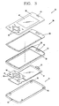
- FIG. 4 is a perspective view of several components of the first body of FIG. 2;
- FIG. 5 is a cross-sectional view of the first body taken along line 5-5 of FIG. 4;
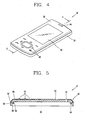
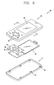
- FIG. 6 is an exploded perspective view of a first body in accordance with an alternative embodiment of the present invention.
- FIG. 7 is a perspective view of the first body taken along line 7-7 of FIG. 6;
- FIG. 8 is an enlarged view of a portion of the first body shown in FIG. 7;
- FIG. 9 is a cross-sectional view of the first body taken along line 7-7 of FIG. 6;
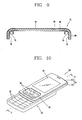
- FIG. 10 is a perspective view of a slide-type mobile device in accordance with an embodiment of the present invention.
- FIG. 11 is a cross-sectional view taken along line 11-11 of FIG. 10;
- FIG. 12 is a perspective view of a housing assembly in accordance with an embodiment of the present invention.
- FIG. 13 is a cross-sectional view of the housing assembly taken along line 13-13 of FIG. 12;
- FIG. 14 is a cross-sectional view of a cover in accordance with another alternative embodiment of the present invention.
- FIG. 15 is a cross-sectional view of a cover in accordance with yet another alternative embodiment.
- slide-type mobile devices First of all, specific examples of slide-type mobile devices will be described, but such teachings apply equally to other types of mobile devices. Accordingly, the various teachings of the present disclosure may be implemented using, for example, slide-type, bar-type, folding-type, and swivel-type, mobile devices.
- Fig. 2 is a perspective view of slide-type mobile device 10 in accordance with an embodiment of the present invention.
- Mobile device 10 includes first body 30 and second body 20.
- the first body is structured to define an enclosure to contain various electrical components necessary for the mobile device.
- first body 30 includes cover 32, frame 34, and housing 31.
- the frame is sized to receive cover 32.
- opaque material is formed over a portion of the cover such that the opaque material is arranged to define an optically transmissive display portion 40.
- the display portion is located on the cover to cooperate with an underlying display.
- cover 32 may further include an integrated input portion.
- the cover may include a plurality of optically transmissive input regions 42. Similar to display portion 40, each of the input regions may be defined or bounded by portions of the opaque material formed over the cover.
- Speaker aperture 44 is shown formed on one end of cover 32, while microphone aperture 45 is shown formed in the wall of frame 34. These elements respectively cooperate with an underlying speaker and microphone (not shown in this figure).
- Second body 20 includes main key pad 22, which is designed to receive input from a user.
- the second body may also include a communication module (not shown) for transmitting and receiving signals, and a main printed circuit board (not shown) in which the communication module is mounted.
- FIG. 3 is an exploded perspective view of the first body of FIG. 2. This figure shows display 12 and touch pad 14, which may be positioned within first body 10. Coupling of cover 32 and frame 34 may be accomplished using, for example, adhesive 60. The adhesive may be positioned on mounting surface 52, which is shown located along an inner perimeter of the frame. Coupling of housing 31 and frame 34 may be accomplished using, for example, cooperating pins and pin receptacles.
- pin receptacles 55 are positioned on an interior region of housing 31. These pin receptacles cooperate with pins and pin receptacles located on the bottom side of frame 34 (not shown in this figure).
- display 12 is positioned relative to display portion 40, and touch pad 14 is positioned relative to a bottom side of input regions 42.
- Touch pad 14 may be implemented using conventional touch pad technologies which are capable of detecting user manipulation or other contact with an associated one or more of input regions 42. During use, the touch pad generates signals which may be communicated to a printed circuit board, for example. Touch pad 14 may be positioned relative to the bottom side of cover 32 using known techniques (e.g., adhesive, tape, and the like). Suitable touch pads include, for example, pressure-sensitive touch pads, capacitance touch pads, and the like.
- Touch pad 14 may also include one or more strategically located light guides 15. As shown, each light guide 15 is associated with an individual input region 42 of the cover. As an example, the touch pad may be shaped to define an aperture which forms an individual light guide. In an embodiment, one or more light sources 16 may be positioned relative to the bottom side of touch pad 14. If desired, the light sources may be directly coupled to the touch pad. Light guides 15 are often implemented to permit light provided by light sources 16 to pass through touch pad 14, and consequently, optically transmissive input regions 42. If desired, optically transmissive material may be formed within some or all of the light guides. This feature enhances the structural integrity of the touch pad.
- Light sources 16 may be implemented using known devices and structures which can provide light at the wavelength of interest to one or more input regions 42. Typical light sources include light emitting diodes (LEDs) and vertical surface emitting lasers (VCSELs), among others.
- LEDs light emitting diodes
- VCSELs vertical surface emitting lasers
- light emitted by light sources 16 is not unnecessarily hindered by structures, which is common in conventional assemblies. More specifically, light emitted by light sources 16 reaches input regions 42 relatively unimpeded. This reduces the number of needed light sources, which consequently reduces the power requirements of the assembly.
- each input region 42 it is not necessary for each input region 42 to have an associated light source 16.
- the number of light sources is fewer than the number of input regions.
- a single light source provides sufficient light to all input regions. Maximum light to the touch keys may be achieved by positioning each light source relatively close to an associated light guide 15.
- Frame 34 is shown having speaker aperture 50, which corresponds with aperture 44 of cover 32. Both apertures are arranged to cooperate with speaker 51.
- FIG. 4 is a perspective view of several components of first body 10 of FIG. 2, and FIG. 5 is a cross-sectional view of the first body taken along line 5-5 of FIG. 4. Note that housing 31 has been omitted from these figures for clarity.
- cover 32 is shown being substantially planar, with display portion 40 and input regions 42 being integrally formed in the cover.
- Cover 32 may be formed from any suitably ridged material which is optically transmissive.
- Methyl methacrylate polymer is one example of material that may be used for the cover.
- frame 34 may be formed of a polycarbonate material which has high impact strength and heat resistance.
- Cover 32 is typically formed from a different material than that used for frame 34, but this is not a requirement.
- cover 32 is formed from transparent material 36, and opaque material 38 is positioned on a surface of the transparent material.
- Input regions 42 and display portion 40 may be defined as areas of the cover which do not include the opaque material. Incident light will be transmitted by optically transmissive regions of the cover, and will not be transmitted by the portions of the cover which include the opaque material. Various types, shapes, and numbers of touch keys may therefore be formed using this technique.
- opaque material 38 may be coated on the surface of transparent member 36 as part of an in-mold injection process. In-mold injection can reduce the number of steps necessary to form cover 32, offering increased manufacturing efficiency and lower production costs.
- Each of the optically transmissive input regions may be shaped to define one or more of a character, a symbol, and a number, among others.
- one or more input regions 42 may be structured using a tactile element projecting from the cover. Each of these tactile elements may be individually associated with one of the input regions.
- Tactile elements enhance the user's ability to interact with the input regions.
- the tactile elements may be formed in a variety of different shapes (e. g., circular, triangular, rectagonal, polygonal, star-like, and the like), as needed or desired.
- the opaque material may be formed over the tactile elements, or such material can be omitted from these elements so that they remain optically transmissive.
- cover 32 and frame 34 may be accomplished using cooperating pins and pin receptacles.
- cover 32 is shown having pins 56, which may be positioned around the perimeter of cover 32 in such a manner that they operatively couple with corresponding pin receptacles 58 of frame 34.
- Coupling of frame 34 to housing 31 may also be accomplished by cooperating pins and pin receptacles.
- pins may be used with pin receptacles 54 (frame 32) and pin receptacles 55 (housing 31).
- FIG. 6 is an exploded perspective view of a first body
- FIG. 7 is a perspective view of the first body taken along line 7-7 of FIG. 6.
- FIG. 8 is an enlarged view of a portion of the first body shown in FIG. 7, and
- FIG. 9 is a cross-sectional view of the first body taken along line 7-7 of FIG. 6.
- first body 69 includes first housing 70 and second housing 71.
- the first housing may be formed from optically transmissive material (as previously described) and typically includes wall 80 which extends along a perimeter of the housing.
- Coupling structure 78 is shown located on an inner portion of this wall of the first housing.
- the coupling structure 78 may be used to couple the first and second housings.
- the coupling structure may be formed within first housing 70 using, for example, double injection molding techniques. Double injection is beneficial in this regard since it reduces processing steps, offering increased manufacturing efficiency and lower production costs.
- Wall 80 may be sized so that it extends past coupling structure 78. This permits the concealment of the coupling structure when the first and second housings 70, 71, are assembled.
- coupling structure 78 and first housing 70 are formed from different materials, but this is not a requirement.
- First housing 70 may be formed from optically transmissive material 36 onto which opaque material 38 has been introduced. Materials 36 and 38 may be implemented using any of the techniques previously described. As a result, optically transmissive input regions 42 and display region 40 may thus be formed. Coupling structure may be formed using, for example, polycarbonate material.
- first and second housings 70, 71 may be accomplished using cooperating pins and pin receptacles.
- pin receptacles 79 are shown formed in coupling structure 78.
- Second housing 71 has corresponding pin receptacles 73 formed along various locations of the interior perimeter. The first and second housings can thus be assembled using pins which cooperate with the various pin receptacles of these housings.
- FIG. 10 is a perspective view of a slide-type mobile device 89 in accordance with an embodiment of the present invention.
- FIG. 11 is a cross-sectional view taken along line 11-11 of FIG. 10.
- the embodiment of FIGS. 10 and 11 is similar in many respects to that which is depicted in FIGS. 2-5.
- One difference relates to the user interface implemented.
- cover 32 of mobile device 89 is shaped to define a plurality of openings 90.
- a corresponding plurality of keys 92 are individually associated with one of the plurality of openings of the cover.
- Each of the keys e.g., push-type, wheel-type, and the like
- Alternatives include providing multiple keys for a single opening, and the use of only one opening sized to receive one or more keys.
- An advantage of these embodiments is that a separate key assembly (or assemblies) may be used in conjunction with cover 32.
- FIG. 12 is a perspective view of a housing assembly in accordance with an embodiment of the present invention.
- FIG. 13 is a cross-sectional view of the housing assembly taken along line 13-13 of FIG. 12.
- the embodiment of FIGS. 12 and 13 is similar in many respects to that which is depicted in FIGS. 6-9. One difference relates to the user interface implemented.
- first housing 70 is shaped to define a plurality of openings 90.
- a corresponding plurality of keys 92 is associated with one of the plurality of openings of the cover.
- Each of the keys e.g., push-type, wheel-type, and the like
- Alternatives include providing multiple keys for a single opening, and the use of only one opening sized to receive one or more keys.
- first housing 70 is typically configured with a suitable housing, such as second housing 71 (FIG. 6).
- FIG. 14 is a cross-sectional view of cover 150 in accordance with another alternative embodiment of the present invention. This example is similar is some respects to the cover depicted in FIG. 5.
- One difference is that coupling of cover 150 is facilitated by pin receptacles 162, which are located along a walled portion of the cover. These pin receptacles may be positioned around the perimeter of cover 150 in such a manner that they operatively couple, via pins, with corresponding pin receptacles located in a lower housing (e.g., second housing 71 of FIG. 6).
- pin receptacles 162 which are located along a walled portion of the cover. These pin receptacles may be positioned around the perimeter of cover 150 in such a manner that they operatively couple, via pins, with corresponding pin receptacles located in a lower housing (e.g., second housing 71 of FIG. 6).
- a lower housing e.g., second housing 71 of FIG. 6
- one or more input regions 42 may be structured as a tactile element projecting from the cover. Examples of such tactile elements are denoted as elements 160.
- FIG. 15 is a cross-sectional view of cover 170 in accordance with yet another alternative embodiment. This example is similar is some respects to the cover depicted in FIG. 14. One difference is that the input regions 42 of the cover of FIG. 14 have been replaced with key buttons 92. For instance, cover 170 is shaped to define a plurality of openings 90. A corresponding plurality of keys 92 is associated with one of the plurality of openings of the cover. The keys and corresponding openings may be implemented using any of the techniques previously described.
Landscapes
- Engineering & Computer Science (AREA)
- Theoretical Computer Science (AREA)
- Computer Hardware Design (AREA)
- Signal Processing (AREA)
- General Engineering & Computer Science (AREA)
- Physics & Mathematics (AREA)
- Human Computer Interaction (AREA)
- General Physics & Mathematics (AREA)
- Computer Networks & Wireless Communication (AREA)
- Mathematical Physics (AREA)
- Microelectronics & Electronic Packaging (AREA)
- Telephone Set Structure (AREA)
- Casings For Electric Apparatus (AREA)
- Transmitters (AREA)
Applications Claiming Priority (1)
| Application Number | Priority Date | Filing Date | Title |
|---|---|---|---|
| KR1020060028094A KR100751943B1 (ko) | 2006-03-28 | 2006-03-28 | 외장 케이스 및 이를 갖는 휴대 단말기 |
Publications (2)
| Publication Number | Publication Date |
|---|---|
| EP1841185A2 true EP1841185A2 (fr) | 2007-10-03 |
| EP1841185A3 EP1841185A3 (fr) | 2008-01-02 |
Family
ID=38179511
Family Applications (1)
| Application Number | Title | Priority Date | Filing Date |
|---|---|---|---|
| EP06024224A Ceased EP1841185A3 (fr) | 2006-03-28 | 2006-11-22 | Boîte pour appareil portable |
Country Status (8)
| Country | Link |
|---|---|
| US (5) | US7599709B2 (fr) |
| EP (1) | EP1841185A3 (fr) |
| JP (1) | JP5117712B2 (fr) |
| KR (1) | KR100751943B1 (fr) |
| CN (1) | CN101047728B (fr) |
| BR (1) | BRPI0604976A (fr) |
| DE (1) | DE202006020349U1 (fr) |
| MX (1) | MXPA06011444A (fr) |
Cited By (7)
| Publication number | Priority date | Publication date | Assignee | Title |
|---|---|---|---|---|
| EP2058729A1 (fr) * | 2007-11-09 | 2009-05-13 | LG Electronics Inc. | Terminal mobile |
| WO2011098548A1 (fr) * | 2010-02-12 | 2011-08-18 | Sagem Wireless | Téléphone portable présentant un marquage |
| EP2444221A1 (fr) * | 2010-10-22 | 2012-04-25 | Research In Motion Limited | Dispositif électronique portable et procédé de fabrication de pièces associé |
| US8618415B2 (en) | 2010-10-22 | 2013-12-31 | Blackberry Limited | Portable electronic device and method of manufacturing parts thereof |
| EP2290493A3 (fr) * | 2009-08-27 | 2014-09-03 | LG Electronics Inc. | Terminal mobile |
| EP2299663A3 (fr) * | 2009-09-18 | 2015-11-25 | Lg Electronics Inc. | Terminal mobile avec un boîtier qui produit un effet optique |
| WO2016138884A1 (fr) * | 2015-03-03 | 2016-09-09 | MYSIMPHONIE a.s. | Corps d'un téléphone mobile simple, un téléphone mobile simple et un procédé de production d'un téléphone mobile simple |
Families Citing this family (72)
| Publication number | Priority date | Publication date | Assignee | Title |
|---|---|---|---|---|
| ATE492841T1 (de) | 2002-06-27 | 2011-01-15 | Nokia Corp | Abdeckung für ein elektronisches gerät und elektronisches gerät mit einer abdeckung |
| USD570338S1 (en) * | 2005-03-23 | 2008-06-03 | Nokia Corporation | Portion of a handset |
| KR100751943B1 (ko) * | 2006-03-28 | 2007-08-24 | 엘지전자 주식회사 | 외장 케이스 및 이를 갖는 휴대 단말기 |
| USD590386S1 (en) | 2006-06-14 | 2009-04-14 | Nokia Corporation | Movable support element for a handset |
| USD589015S1 (en) | 2006-11-28 | 2009-03-24 | Nokia Corporation | Handset |
| USD569830S1 (en) * | 2006-07-07 | 2008-05-27 | Lg Electronics Inc. | Cellular phone |
| KR100778483B1 (ko) | 2006-07-27 | 2007-11-21 | 엘지전자 주식회사 | 휴대 단말기 |
| TWD121475S1 (zh) | 2006-08-18 | 2008-02-21 | 諾基亞股份有限公司 | 手機 |
| USD584708S1 (en) * | 2006-12-04 | 2009-01-13 | Huawei Technologies Co., Ltd. | Handset |
| JP4781989B2 (ja) * | 2006-12-15 | 2011-09-28 | 富士通株式会社 | 電子機器および電子機器用筐体 |
| USD570815S1 (en) * | 2007-06-13 | 2008-06-10 | Samsung Electronics Co., Ltd. | Mobile phone |
| USD576595S1 (en) * | 2007-06-21 | 2008-09-09 | Samsung Electronics Co., Ltd. | Portable telephone |
| US8019394B2 (en) * | 2007-06-29 | 2011-09-13 | Motorola Mobility, Inc. | Component packaging for handheld communication devices |
| USD579434S1 (en) * | 2007-08-02 | 2008-10-28 | Samsung Electronics Co., Ltd. | Mobile phone |
| USD586310S1 (en) * | 2007-08-09 | 2009-02-10 | Samsung Electronics Co., Ltd. | Portable phone |
| USD579896S1 (en) * | 2007-08-24 | 2008-11-04 | Samsung Electronics Co., Ltd. | Portable phone |
| JP2009064295A (ja) | 2007-09-07 | 2009-03-26 | Tdk Corp | タッチスイッチ用中間体、インモールド用金型およびタッチスイッチ用中間体製造方法 |
| KR100927892B1 (ko) * | 2007-09-12 | 2009-11-23 | 배인철 | 휴대용 단말기의 터치 패널 |
| USD572229S1 (en) * | 2007-09-27 | 2008-07-01 | Samsung Electronics Co., Ltd. | Portable telephone |
| USD576141S1 (en) * | 2007-09-28 | 2008-09-02 | Samsung Electronics Co., Ltd. | Cellular phone |
| USD576140S1 (en) * | 2007-09-28 | 2008-09-02 | Samsung Electronics Co., Ltd. | Cellular phone |
| USD575759S1 (en) * | 2007-09-28 | 2008-08-26 | Samsung Electronics Co., Ltd. | Cellular phone |
| USD583344S1 (en) * | 2007-10-10 | 2008-12-23 | Samsung Electronics Co., Ltd. | Mobile phone |
| KR100837252B1 (ko) * | 2007-11-14 | 2008-06-12 | (주)쉘-라인 | 전자기기용 케이스 및 그 제조방법 |
| US20090170571A1 (en) * | 2007-12-31 | 2009-07-02 | Motorola, Inc. | Method and apparatus for partial flip-open assist of ultra thin clam communication devices |
| TWI352566B (en) * | 2008-03-31 | 2011-11-11 | Wistron Neweb Corp | Housing structure of hand-hled electronic divice |
| US7933123B2 (en) * | 2008-04-11 | 2011-04-26 | Apple Inc. | Portable electronic device with two-piece housing |
| USD603824S1 (en) * | 2008-05-21 | 2009-11-10 | Lg Electronics Inc. | Cellular phone |
| USD592170S1 (en) * | 2008-05-23 | 2009-05-12 | Samsung Electronics Co., Ltd. | Portable phone |
| KR101455805B1 (ko) * | 2008-06-12 | 2014-11-03 | 엘지전자 주식회사 | 휴대단말기 및 그 제조방법 |
| USD599318S1 (en) * | 2008-07-14 | 2009-09-01 | Samsung Electronics Co., Ltd. | Cellular phone |
| USD601991S1 (en) * | 2008-09-10 | 2009-10-13 | Samsung Electronics Co., Ltd. | Portable phone |
| KR101484944B1 (ko) | 2008-10-02 | 2015-01-22 | 삼성전자 주식회사 | 전자기기 케이스 및 이의 제조방법 |
| KR101491573B1 (ko) | 2008-10-09 | 2015-02-09 | 삼성전자 주식회사 | 디스플레이 장치 및 그 전면커버 |
| KR101405497B1 (ko) * | 2008-10-22 | 2014-06-27 | 삼성전자주식회사 | 시각 디자인 표시 장치 |
| USD609701S1 (en) * | 2008-11-20 | 2010-02-09 | Cheng Uei Precision Industry Co., Ltd. | Wireless transceiver |
| US8204560B2 (en) * | 2008-12-17 | 2012-06-19 | Motorola Mobility, Inc. | Clamshell phone with edge access |
| KR101563366B1 (ko) * | 2009-02-04 | 2015-10-26 | 삼성전자주식회사 | 이물질 차단 장치를 구비한 휴대용 전자 장치 |
| USD610134S1 (en) * | 2009-03-18 | 2010-02-16 | Nokia Corporation | Wireless modem housing |
| US20100238984A1 (en) * | 2009-03-19 | 2010-09-23 | Motorola, Inc. | Spatial Information Feedback in Wireless Communication Systems |
| USD617758S1 (en) * | 2009-03-27 | 2010-06-15 | Sony Ericsson Mobile Communications Ab | Mobile phone |
| US8244317B2 (en) * | 2009-06-08 | 2012-08-14 | Motorola Mobility Llc | Indicator shelf for portable electronic device |
| US9002354B2 (en) | 2009-06-12 | 2015-04-07 | Google Technology Holdings, LLC | Interference control, SINR optimization and signaling enhancements to improve the performance of OTDOA measurements |
| USD618228S1 (en) * | 2009-06-19 | 2010-06-22 | Nokia Corporation | Handset front cover |
| USD616875S1 (en) * | 2009-06-19 | 2010-06-01 | Nokia Corporation | Handset |
| KR101580331B1 (ko) * | 2009-10-05 | 2015-12-23 | 삼성전자주식회사 | 투과성을 가지는 사출물 |
| US20110085588A1 (en) * | 2009-10-09 | 2011-04-14 | Motorola-Mobility, Inc. | Method for precoding based on antenna grouping |
| KR20110058975A (ko) * | 2009-11-27 | 2011-06-02 | 삼성전자주식회사 | 슬라이딩형 휴대용 단말기 |
| CN201766775U (zh) * | 2010-03-17 | 2011-03-16 | 中兴通讯股份有限公司 | 移动终端的外壳及移动终端 |
| US9203489B2 (en) | 2010-05-05 | 2015-12-01 | Google Technology Holdings LLC | Method and precoder information feedback in multi-antenna wireless communication systems |
| US8509338B2 (en) | 2010-05-05 | 2013-08-13 | Motorola Mobility Llc | Method and precoder information feedback in multi-antenna wireless communication systems |
| US8537658B2 (en) | 2010-08-16 | 2013-09-17 | Motorola Mobility Llc | Method of codebook design and precoder feedback in wireless communication systems |
| CN102049838A (zh) * | 2010-11-09 | 2011-05-11 | 深圳庆和胶粘制品有限公司 | 具有视窗口的金属件与塑胶成型品成型方法及其应用 |
| KR101889478B1 (ko) * | 2011-08-08 | 2018-08-17 | 엘지전자 주식회사 | 프론트 프레임, 이를 포함하는 이동 단말기 및 그 제조방법 |
| CN105979039B (zh) * | 2011-10-20 | 2021-01-29 | 华为技术有限公司 | 包括具有键装置的盖单元的移动终端 |
| US9813262B2 (en) | 2012-12-03 | 2017-11-07 | Google Technology Holdings LLC | Method and apparatus for selectively transmitting data using spatial diversity |
| US9591508B2 (en) | 2012-12-20 | 2017-03-07 | Google Technology Holdings LLC | Methods and apparatus for transmitting data between different peer-to-peer communication groups |
| US9979531B2 (en) | 2013-01-03 | 2018-05-22 | Google Technology Holdings LLC | Method and apparatus for tuning a communication device for multi band operation |
| US10229697B2 (en) | 2013-03-12 | 2019-03-12 | Google Technology Holdings LLC | Apparatus and method for beamforming to obtain voice and noise signals |
| US20140339063A1 (en) * | 2013-05-16 | 2014-11-20 | Research In Motion Limited | Method And Apparatus Pertaining To A Keyboard Cover Having Light-Masking Paint |
| US9386542B2 (en) | 2013-09-19 | 2016-07-05 | Google Technology Holdings, LLC | Method and apparatus for estimating transmit power of a wireless device |
| US9549290B2 (en) | 2013-12-19 | 2017-01-17 | Google Technology Holdings LLC | Method and apparatus for determining direction information for a wireless device |
| JP6264905B2 (ja) * | 2014-01-31 | 2018-01-24 | 住友電気工業株式会社 | 複合部材、及び複合部材の製造方法 |
| US9491007B2 (en) | 2014-04-28 | 2016-11-08 | Google Technology Holdings LLC | Apparatus and method for antenna matching |
| US9478847B2 (en) | 2014-06-02 | 2016-10-25 | Google Technology Holdings LLC | Antenna system and method of assembly for a wearable electronic device |
| US11191528B2 (en) * | 2015-07-09 | 2021-12-07 | DePuy Synthes Products, Inc. | External hand control for surgical power tool |
| WO2017026884A1 (fr) * | 2015-08-07 | 2017-02-16 | Motorola Solutions, Inc. | Support de dispositif de télécommunication portatif |
| JP7053532B2 (ja) * | 2019-06-07 | 2022-04-12 | 株式会社ニフコ | ディスプレイ装置及びその製造方法並びにディスプレイ装置を備えるインストルメントパネル |
| KR102786893B1 (ko) * | 2020-08-04 | 2025-03-26 | 삼성전자주식회사 | 안테나를 포함하는 전자 장치 및 동작 방법 |
| RU200438U1 (ru) * | 2020-08-04 | 2020-10-23 | Общество с ограниченной ответственностью "Велтер" (ООО "Велтер") | Устройство защиты информационного обмена при использовании персонального устройства инфокоммуникации |
| MX2023004694A (es) * | 2020-10-23 | 2023-05-09 | Popsockets Llc | Aparato para proporcionar activacion de funciones de emergencia para dispositivos electronicos moviles. |
| US12287670B2 (en) * | 2022-03-08 | 2025-04-29 | Motorola Mobility Llc | Electronic devices having morphing device housings allowing wearable and handheld modes of operation |
Citations (3)
| Publication number | Priority date | Publication date | Assignee | Title |
|---|---|---|---|---|
| EP0676781A1 (fr) | 1994-04-08 | 1995-10-11 | Nokia Mobile Phones Ltd. | Clavier |
| DE19934707C1 (de) | 1999-07-23 | 2001-02-15 | Siemens Ag | Gehäuseoberschale für Geräte mit integrierter Tastatur und Display |
| US20040061685A1 (en) * | 2000-10-31 | 2004-04-01 | Toni Ostergard | Double-sided keyboard for use in an electronic device |
Family Cites Families (41)
| Publication number | Priority date | Publication date | Assignee | Title |
|---|---|---|---|---|
| JP2515444B2 (ja) | 1991-05-31 | 1996-07-10 | 富士通株式会社 | 電話機 |
| WO1998013980A1 (fr) | 1996-09-27 | 1998-04-02 | Nissha Printing Co., Ltd. | Element de fermeture superieur d'un boitier de telephone portatif et procede de production de cet element |
| US5884772A (en) * | 1997-09-04 | 1999-03-23 | Motorola, Inc. | Electronic device having multiple user interface configurations |
| DE19901834A1 (de) * | 1999-01-19 | 2000-07-20 | Leybold Systems Gmbh | Verfahren zum Beschichten von Substraten aus Kunststoff |
| FI990330L (fi) * | 1999-02-17 | 2000-08-18 | Nokia Mobile Phones Ltd | Kannettavan tietoliikennelaitteen mekaaninen rakenne ja kokoonpanomene telmä |
| KR100359519B1 (ko) * | 2000-03-16 | 2002-10-31 | 주식회사 동남 실리콘 | 키패드 일체형 통신기기용 전면 커버 |
| US6898283B2 (en) * | 2000-05-05 | 2005-05-24 | Nokia Mobile Phones Ltd. | Exchangable housing cover for a portable radio communication device |
| JP4485019B2 (ja) | 2000-06-06 | 2010-06-16 | ポリマテック株式会社 | キーシートの製造方法 |
| US7054441B2 (en) * | 2000-12-12 | 2006-05-30 | Research In Motion Limited | Mobile device having a protective user interface cover |
| US7373180B2 (en) * | 2001-05-25 | 2008-05-13 | Kyocera Wireless Corp. | Method and apparatus for accentuating graphical elements on a mobile handset housing |
| US7095986B2 (en) * | 2001-07-17 | 2006-08-22 | Wildseed Ltd. | Interchangeable covering with keys for personalizing mobile electronic communication devices |
| JP2003110675A (ja) * | 2001-09-28 | 2003-04-11 | Sanyo Electric Co Ltd | 携帯電話 |
| TW576074B (en) * | 2001-11-06 | 2004-02-11 | Benq Corp | Portable phone with replaceable housing and the assembly method thereof |
| JP4076227B2 (ja) * | 2001-12-21 | 2008-04-16 | 旭化成ケミカルズ株式会社 | 酸化物触媒組成物 |
| EP1477011A1 (fr) | 2002-02-21 | 2004-11-17 | Siemens Aktiengesellschaft | Boitier ou partie de boitier, procede de fabrication d'un boitier ou d'une partie de boitier, et outil permettant la mise en oeuvre dudit procede |
| JP3948988B2 (ja) * | 2002-03-27 | 2007-07-25 | 三洋電機株式会社 | カメラ付き携帯電話機 |
| US7003267B2 (en) * | 2002-05-14 | 2006-02-21 | Siemens Communications, Inc. | Internal part design, molding and surface finish for cosmetic appearance |
| TW537490U (en) | 2002-07-05 | 2003-06-11 | Quanta Comp Inc | Structure of touch pad buttons |
| US7558594B2 (en) * | 2002-07-16 | 2009-07-07 | Nokia Corporation | Flexible cover for a mobile telephone |
| DE10232947A1 (de) * | 2002-07-19 | 2004-01-29 | Siemens Ag | Behältnis, insbesondere Gehäuse für ein Telefonmobilteil sowie Verfahren zur Herstellung eines Gehäuseteils |
| US7184718B2 (en) * | 2002-07-30 | 2007-02-27 | Nokia Corporation | Transformable mobile station |
| US7366555B2 (en) * | 2002-09-30 | 2008-04-29 | Nokia Corporation | Mobile station enclosure |
| US20040125947A1 (en) * | 2002-12-30 | 2004-07-01 | Michael Charlier | Method and apparatus to deploy a mini-touchpad on a cellular phone |
| US6876543B2 (en) * | 2003-03-07 | 2005-04-05 | Motorola, Inc. | Housing for a communication device and method assembling the same |
| TWM240050U (en) * | 2003-04-02 | 2004-08-01 | Elan Microelectronics Corp | Capacitor touch panel with integrated keyboard and handwriting function |
| KR100536939B1 (ko) | 2003-07-11 | 2005-12-19 | 엘지전자 주식회사 | 슬라이드 타입 휴대용 단말기 |
| US7181251B2 (en) * | 2003-10-22 | 2007-02-20 | Nokia Corporation | Mobile communication terminal with multi orientation user interface |
| JP2005142942A (ja) | 2003-11-07 | 2005-06-02 | Sony Corp | 電子機器、フォーカス表示方法及びそのプログラム |
| US7236588B2 (en) * | 2003-12-12 | 2007-06-26 | Nokia Corporation | Interlocking cover for mobile terminals |
| CN1629880A (zh) | 2003-12-19 | 2005-06-22 | 升达科技股份有限公司 | 触控输入模块及具有该触控输入模块的手持式电子设备 |
| US7079875B2 (en) * | 2003-12-19 | 2006-07-18 | Motorola, Inc. | Housing assembly with biased and removable door |
| FI20031892A0 (fi) | 2003-12-22 | 2003-12-22 | Perlos Oyj | Kannettavan elektroniikkalaitteen kuoriosa ja menetelmä sen valmistamiseksi |
| CA2551595C (fr) | 2003-12-26 | 2011-02-08 | Nissha Printing Co., Ltd. | Appareil electronique muni d'un panneau de protection, panneau de protection et methode de fabrication de panneaux de protection |
| TWM265866U (en) * | 2004-02-20 | 2005-05-21 | Fih Co Ltd | Replaceable panel for portable electronic device |
| ATE475257T1 (de) | 2004-06-01 | 2010-08-15 | Research In Motion Ltd | Gehäuse für ein kommunikationsgerät mit einem deckel für ein display und einen lautsprecher |
| US7398114B2 (en) * | 2004-11-19 | 2008-07-08 | Nokia Corporation | Mobile station body comprised of stacked elements |
| JP4580738B2 (ja) | 2004-11-22 | 2010-11-17 | オリンパスイメージング株式会社 | 電子機器 |
| KR200390092Y1 (ko) | 2005-05-04 | 2005-07-18 | 이해식 | 금속재 키패드 |
| US20070142101A1 (en) * | 2005-08-23 | 2007-06-21 | Sudhir Seshagiri | Mobile electronic device having a rotatable keypad |
| KR200413540Y1 (ko) | 2006-01-17 | 2006-04-07 | 주식회사 신화엠에스 | 핸드폰용 키패드 |
| KR100751943B1 (ko) * | 2006-03-28 | 2007-08-24 | 엘지전자 주식회사 | 외장 케이스 및 이를 갖는 휴대 단말기 |
-
2006
- 2006-03-28 KR KR1020060028094A patent/KR100751943B1/ko not_active Expired - Fee Related
- 2006-10-04 MX MXPA06011444A patent/MXPA06011444A/es active IP Right Grant
- 2006-11-21 US US11/602,748 patent/US7599709B2/en not_active Expired - Fee Related
- 2006-11-22 DE DE202006020349U patent/DE202006020349U1/de not_active Expired - Lifetime
- 2006-11-22 EP EP06024224A patent/EP1841185A3/fr not_active Ceased
- 2006-11-29 BR BRPI0604976-1A patent/BRPI0604976A/pt not_active Application Discontinuation
- 2006-12-18 JP JP2006339648A patent/JP5117712B2/ja not_active Expired - Fee Related
-
2007
- 2007-01-17 CN CN2007100022570A patent/CN101047728B/zh not_active Expired - Fee Related
-
2009
- 2009-06-15 US US12/484,943 patent/US9239591B2/en active Active
-
2015
- 2015-12-11 US US14/967,192 patent/US9450631B2/en active Active
-
2016
- 2016-02-25 US US15/053,866 patent/US9509812B2/en active Active
- 2016-08-26 US US15/249,169 patent/US9685987B2/en active Active
Patent Citations (3)
| Publication number | Priority date | Publication date | Assignee | Title |
|---|---|---|---|---|
| EP0676781A1 (fr) | 1994-04-08 | 1995-10-11 | Nokia Mobile Phones Ltd. | Clavier |
| DE19934707C1 (de) | 1999-07-23 | 2001-02-15 | Siemens Ag | Gehäuseoberschale für Geräte mit integrierter Tastatur und Display |
| US20040061685A1 (en) * | 2000-10-31 | 2004-04-01 | Toni Ostergard | Double-sided keyboard for use in an electronic device |
Cited By (13)
| Publication number | Priority date | Publication date | Assignee | Title |
|---|---|---|---|---|
| RU2399085C2 (ru) * | 2007-11-09 | 2010-09-10 | ЭлДжи ЭЛЕКТРОНИКС ИНК. | Мобильный терминал |
| US9880690B2 (en) | 2007-11-09 | 2018-01-30 | Lg Electronics Inc. | Mobile terminal |
| EP2058729A1 (fr) * | 2007-11-09 | 2009-05-13 | LG Electronics Inc. | Terminal mobile |
| US9462097B2 (en) | 2007-11-09 | 2016-10-04 | Lg Electronics Inc. | Mobile terminal |
| US9244534B2 (en) | 2009-08-27 | 2016-01-26 | Lg Electronics Inc. | Mobile terminal |
| EP2290493A3 (fr) * | 2009-08-27 | 2014-09-03 | LG Electronics Inc. | Terminal mobile |
| EP2299663A3 (fr) * | 2009-09-18 | 2015-11-25 | Lg Electronics Inc. | Terminal mobile avec un boîtier qui produit un effet optique |
| FR2956514A1 (fr) * | 2010-02-12 | 2011-08-19 | Sagem Wireless | Telephone portable presentant un marquage |
| WO2011098548A1 (fr) * | 2010-02-12 | 2011-08-18 | Sagem Wireless | Téléphone portable présentant un marquage |
| US8618415B2 (en) | 2010-10-22 | 2013-12-31 | Blackberry Limited | Portable electronic device and method of manufacturing parts thereof |
| EP2444221A1 (fr) * | 2010-10-22 | 2012-04-25 | Research In Motion Limited | Dispositif électronique portable et procédé de fabrication de pièces associé |
| US9694520B2 (en) | 2010-10-22 | 2017-07-04 | Blackberry Limited | Method of manufacturing portable electronic device |
| WO2016138884A1 (fr) * | 2015-03-03 | 2016-09-09 | MYSIMPHONIE a.s. | Corps d'un téléphone mobile simple, un téléphone mobile simple et un procédé de production d'un téléphone mobile simple |
Also Published As
| Publication number | Publication date |
|---|---|
| US20160099739A1 (en) | 2016-04-07 |
| EP1841185A3 (fr) | 2008-01-02 |
| US20090253472A1 (en) | 2009-10-08 |
| US9685987B2 (en) | 2017-06-20 |
| CN101047728A (zh) | 2007-10-03 |
| US9509812B2 (en) | 2016-11-29 |
| MXPA06011444A (es) | 2007-09-27 |
| US20070232370A1 (en) | 2007-10-04 |
| BRPI0604976A (pt) | 2007-11-27 |
| JP5117712B2 (ja) | 2013-01-16 |
| JP2007267355A (ja) | 2007-10-11 |
| US20160365887A1 (en) | 2016-12-15 |
| CN101047728B (zh) | 2013-01-16 |
| KR100751943B1 (ko) | 2007-08-24 |
| US9239591B2 (en) | 2016-01-19 |
| DE202006020349U1 (de) | 2008-05-21 |
| US20160182695A1 (en) | 2016-06-23 |
| US7599709B2 (en) | 2009-10-06 |
| US9450631B2 (en) | 2016-09-20 |
Similar Documents
| Publication | Publication Date | Title |
|---|---|---|
| US9685987B2 (en) | Case for a hand held device | |
| RU2341032C1 (ru) | Кнопочный узел и мобильный терминал с этим узлом | |
| JP4880015B2 (ja) | キーパッドアセンブリおよび携帯端末機 | |
| US7825907B2 (en) | Touch key assembly for a mobile terminal | |
| EP1507273B1 (fr) | Ensemble d'un clavier | |
| EP1914964B1 (fr) | Terminal mobile comprenant un couvercle amovible pour le clavier | |
| EP1744522B1 (fr) | Illumination d'un clavier pour un terminal portable | |
| CN1930858B (zh) | 手机的金属键盘组件及其制造方法 | |
| US7982718B2 (en) | Mobile terminal with back-lighted directional keys | |
| US8049728B2 (en) | Touch key assembly for a mobile terminal | |
| CN201498397U (zh) | 按键组件 | |
| US8710382B2 (en) | Keypad assembly for electronic devices | |
| US20060097035A1 (en) | Size effective keypad switching and backlighting scheme | |
| US9157613B2 (en) | Mobile electronic device | |
| EP2270824B1 (fr) | Clavier avec protection contre l'eau et la poussière | |
| CN213845111U (zh) | 键盘组件和电子装置 | |
| JP2007073445A (ja) | キー操作部及び電子機器 | |
| KR100925823B1 (ko) | 돌기가 구비되어 있는 돔 시트 | |
| JP4699404B2 (ja) | 携帯電子機器 | |
| US8246186B2 (en) | Light-guide board assembly and portable electronic device using same | |
| US20130153386A1 (en) | Electronic device with keypad assembly | |
| JP2007073446A (ja) | キー操作部及び電子機器 | |
| JP2008257949A (ja) | 携帯電子機器 |
Legal Events
| Date | Code | Title | Description |
|---|---|---|---|
| PUAI | Public reference made under article 153(3) epc to a published international application that has entered the european phase |
Free format text: ORIGINAL CODE: 0009012 |
|
| AK | Designated contracting states |
Kind code of ref document: A2 Designated state(s): AT BE BG CH CY CZ DE DK EE ES FI FR GB GR HU IE IS IT LI LT LU LV MC NL PL PT RO SE SI SK TR |
|
| AX | Request for extension of the european patent |
Extension state: AL BA HR MK YU |
|
| PUAL | Search report despatched |
Free format text: ORIGINAL CODE: 0009013 |
|
| AK | Designated contracting states |
Kind code of ref document: A3 Designated state(s): AT BE BG CH CY CZ DE DK EE ES FI FR GB GR HU IE IS IT LI LT LU LV MC NL PL PT RO SE SI SK TR |
|
| AX | Request for extension of the european patent |
Extension state: AL BA HR MK YU |
|
| 17P | Request for examination filed |
Effective date: 20080702 |
|
| 17Q | First examination report despatched |
Effective date: 20080807 |
|
| AKX | Designation fees paid |
Designated state(s): AT BE BG CH CY CZ DE DK EE ES FI FR GB GR HU IE IS IT LI LT LU LV MC NL PL PT RO SE SI SK TR |
|
| APBK | Appeal reference recorded |
Free format text: ORIGINAL CODE: EPIDOSNREFNE |
|
| APBN | Date of receipt of notice of appeal recorded |
Free format text: ORIGINAL CODE: EPIDOSNNOA2E |
|
| APBR | Date of receipt of statement of grounds of appeal recorded |
Free format text: ORIGINAL CODE: EPIDOSNNOA3E |
|
| APAF | Appeal reference modified |
Free format text: ORIGINAL CODE: EPIDOSCREFNE |
|
| RAP1 | Party data changed (applicant data changed or rights of an application transferred) |
Owner name: LG ELECTRONICS INC. |
|
| APBT | Appeal procedure closed |
Free format text: ORIGINAL CODE: EPIDOSNNOA9E |
|
| STAA | Information on the status of an ep patent application or granted ep patent |
Free format text: STATUS: THE APPLICATION HAS BEEN REFUSED |
|
| 18R | Application refused |
Effective date: 20110926 |