EP1841631B1 - Systeme de fixation pour essuie-glace de lunette arriere de vehicule - Google Patents
Systeme de fixation pour essuie-glace de lunette arriere de vehicule Download PDFInfo
- Publication number
- EP1841631B1 EP1841631B1 EP05850236A EP05850236A EP1841631B1 EP 1841631 B1 EP1841631 B1 EP 1841631B1 EP 05850236 A EP05850236 A EP 05850236A EP 05850236 A EP05850236 A EP 05850236A EP 1841631 B1 EP1841631 B1 EP 1841631B1
- Authority
- EP
- European Patent Office
- Prior art keywords
- latching
- bearing body
- fastening system
- vehicle
- wiper
- Prior art date
- Legal status (The legal status is an assumption and is not a legal conclusion. Google has not performed a legal analysis and makes no representation as to the accuracy of the status listed.)
- Expired - Lifetime
Links
Images



Classifications
-
- B—PERFORMING OPERATIONS; TRANSPORTING
- B60—VEHICLES IN GENERAL
- B60S—SERVICING, CLEANING, REPAIRING, SUPPORTING, LIFTING, OR MANOEUVRING OF VEHICLES, NOT OTHERWISE PROVIDED FOR
- B60S1/00—Cleaning of vehicles
- B60S1/02—Cleaning windscreens, windows or optical devices
- B60S1/04—Wipers or the like, e.g. scrapers
- B60S1/32—Wipers or the like, e.g. scrapers characterised by constructional features of wiper blade arms or blades
- B60S1/34—Wiper arms; Mountings therefor
- B60S1/3488—Means for mounting wiper arms onto the vehicle
- B60S1/349—Means for mounting the wiper bearing to the vehicle body
-
- B—PERFORMING OPERATIONS; TRANSPORTING
- B60—VEHICLES IN GENERAL
- B60S—SERVICING, CLEANING, REPAIRING, SUPPORTING, LIFTING, OR MANOEUVRING OF VEHICLES, NOT OTHERWISE PROVIDED FOR
- B60S1/00—Cleaning of vehicles
- B60S1/02—Cleaning windscreens, windows or optical devices
- B60S1/56—Cleaning windscreens, windows or optical devices specially adapted for cleaning other parts or devices than front windows or windscreens
- B60S1/58—Cleaning windscreens, windows or optical devices specially adapted for cleaning other parts or devices than front windows or windscreens for rear windows
- B60S1/583—Cleaning windscreens, windows or optical devices specially adapted for cleaning other parts or devices than front windows or windscreens for rear windows including wiping devices
-
- B—PERFORMING OPERATIONS; TRANSPORTING
- B60—VEHICLES IN GENERAL
- B60S—SERVICING, CLEANING, REPAIRING, SUPPORTING, LIFTING, OR MANOEUVRING OF VEHICLES, NOT OTHERWISE PROVIDED FOR
- B60S1/00—Cleaning of vehicles
- B60S1/02—Cleaning windscreens, windows or optical devices
- B60S1/04—Wipers or the like, e.g. scrapers
- B60S1/043—Attachment of the wiper assembly to the vehicle
- B60S1/0438—Attachement of separate wiper motor assembly to the vehicle
Definitions
- the invention relates to a fastening arrangement for a rear window wiper on a vehicle, in which the electric drive device is arranged in the interior of the vehicle body and the wiper shaft carrying the rear window wiper is guided to the outside.
- Rear wiper devices of the type described above generally have a wiper motor and a worm gear coupled to its output shaft, on the worm wheel eccentrically a pin is mounted, which acts on a coupling rod, the rotational movement of the worm wheel on a sprocket segment and a non-rotatably connected to the wiper shaft Gear or segment in a pendulum motion of the wiper shaft and arranged on this wiper arm.
- the wiper motor can also be a reversible motor, which is connected to a planetary gear, the output shaft is also the wiper shaft.
- the drive units (drive devices) are each arranged inside the vehicle, and the wiper shaft and a bearing for these are guided through a through hole to the outside.
- the arrangement may be made so that the respective drive device fixed to the body structure and the wiper shaft are guided through the lower edge of the rear window in the middle.
- the associated advantage is a large wiping field with a pendulum motion of the wiper arm in an angular range of 180 °, whereby the corner regions of the rear window can be detected with.
- the arrangement requires the introduction of a corresponding hole in the rear window.
- the wiper shaft is rotatably mounted in a sleeve-like spacer by means of a bushing (wiper shaft bearing), which extends with play through an opening in the rear window.
- a bushing wiper shaft bearing
- This clearance is sealed by two annular sealing members of an elastomeric material by means of a glass protector disposed between the outer circumference of the sleeve and the inner peripheries of the two circular sealing members.
- the latter also prevent the transmission of mechanical vibrations from the wiper shaft to the rear window (acoustic decoupling).
- the determination of the windshield wiper device is carried out in addition to a body baffle with the help of a bracket to which the wiper motor is attached.
- At one in the DE 694 06 244 T2 described mounting arrangement is between a wiper shaft receiving bearing and a through hole (opening) in the rear window the vehicle or in a part of the vehicle body, a remote mounting sleeve inserted to allow the attachment of the drive device with a clamping nut on a extending on the outside of the vehicle threaded portion of the bearing. Between the mounting sleeve and the edge of the through hole, a seal is arranged, on which the clamping nut rests with a washer.
- the drive unit is attached to a mounting plate which is arranged fixed to the vehicle.
- a generic mounting arrangement is from the WO-A-01/08945 known.
- the insert is advantageously connected by an adhesive bond with the body panel and the outside is designed such that it is flush with the rear window.
- the inside of the vehicle formed into a mounting bracket insert takes the bearing body with the wiper shaft and connected to this drive device via a latching connection so that the entire windshield wiper system is easily releasably attached to the insert. A screwing the same with the vehicle body is unnecessary so that the assembly process is shortened.
- the vehicle inner side end portion of the support bracket may be formed into a latching sleeve consisting of a plurality of axially parallel latching segments for the bearing body, which engages behind an annular bead formed in this latching state.
- the locking segments bearing body side be adapted to the annular bead and enclose them positively in VerrastungsSullivan, which contributes to the stability and reliability of the attachment, especially in conjunction with a clamp that can be arranged on the locking sleeve and presses the locking segments to the bearing body.
- the locking connection between the bearing body and the support bracket or insert can also be designed such that the bearing body has on its peripheral surface formed in the axial direction locking element with a molded on the drive device side of the molded mushroom-shaped locking head which engages in a trained on the support bracket guide groove in which in the direction of the vehicle outside on the locking element to inclined elastic locking webs are formed, which engage behind the locking head in the Verrastungsposition.
- the locking webs are to be bent out of the rear grip and thereby to press into trained pockets.
- a rubber-elastic element is arranged, which seals the bearing body relative to the support bracket and thus the windshield wiper device relative to the insert in the axial-radial direction.
- the rubber-elastic element takes over the acoustic decoupling of the drive device from the insert and thus of the vehicle body and of the Fahrzugemia. Further fastening and decoupling omitted.
- the rubber-elastic element may be formed as an axially extending sealing sleeve, which is produced in a space provided between the bearing body and the support bracket for this space by injecting the rubber-elastic material.
- the rubber-elastic element may be provided in the arrangement region of the sealing sleeve or in the region of the intermediate space with concentric grooves.
- Fig. 1 shows a arranged on the rear window 1 a tailgate 2 of a vehicle windshield wiper system with a pendulum driven wiper shaft 3, a non-rotatably mounted on this wiper arm 4 and at a free end fixed to the vehicle spray nozzle 5, which will not be discussed further below, and a Connecting device 6 for a wiper blade 7.
- the wiper shaft 3 and the vehicle inside arranged electrical drive device (30, Fig. 3 ) for these are mounted on an insert 8 made of plastic, which in a recess (9, Fig. 2 ) is formed in the adjacent to the rear window 1 body panel 10.
- This insert 8 allows the arrangement of the wiper shaft 3 in the boundary region between the body panel 10 and the rear window 1, so that the wiper arm 4 and wiper blade 7 formed wiper sweeps a wiping field 11 of substantially 180 °, which is indicated by dashed lines.
- the insert 8 has a vehicle interior side formed and inserted into the recess 9 mounting plate 13 with a support bracket 14 and a vehicle outside trained and integrally connected thereto cover plate 15, which overlaps the recess 9 surrounding body panel edge outside and in a is arranged by the outer body panel 16 formed recess 17, with its outer surface is flush and a uniform joint 18 is formed with this.
- cover plate 15 In the lateral transition regions between the plates 13 and 15, a thin wall projection 19 is formed in each case, which covers the given in the recess 9 between the body panel edge and the support bar 13 gap 20.
- an opening 22 is formed, the arrangement and implementation of the in a bearing body (21, Fig.
- the support bracket 14 has at its Vehicle inside end portion of a detent segments 23 formed detent sleeve 24 for connection to the bearing body (21).
- This insert 8 is connected by means of a bead of adhesive 25 with the recess 9 surrounding body panel edge cohesively.
- the rear window 1 is adapted to the shape of the cover plate 15 and is positively on derem upper edge 26 and on the adjoining edge 27 of the body outer panel 16 in the region of the recess 17 and is by means of an adhesive layer, not shown on the support plate 13 and by means of Adhesive bead 25 firmly connected to the body panel edge.
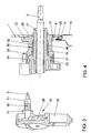
- Fig. 3 shows a drive device 30 formed by a wiper motor 28 and a gear 29 with the oscillating driven and guided in the bearing body 21 wiper shaft 3 for rotationally fixed arrangement of the wiper arm 4, wherein the drive device connected to the bearing body 21 drive device side, an annular bead 31 which is connected to the latching sleeve 24th the support bracket 14 is engageable, and has concentrically arranged grooves 32 on its circumference.
- the support bracket 14 encloses the bearing body 21, wherein the locking segments 23 engage behind the annular bead 31, so that the bearing body 21 carrying the drive device 30 is firmly, but releasably braced with the support bracket 14.
- the locking segments 23 are peripherally provided with a recess 33 for receiving a clamp 34, which stabilizes the latching connection and secures against rotation of the bearing body 21 in the bracket 14.
- annular gap 35 is formed in the region between the front region of the bearing body 21 and the annular bead 31, in which the bearing body 21 is provided with the concentrically arranged grooves 32 and in which a sealing and at the same acoustic decoupling element 36th is injected from a rubber-elastic material.
- a support bracket 37 which is formed inside the vehicle inside the insert 8, and a bearing body 38
- the latter have on its peripheral surface formed in the axial direction arrow-shaped locking element 39 with a mushroom-shaped locking head 40 and the support bracket 37 a guide 41 and a latching recess 42 for the locking element 39.
- two elastically bendable locking webs 43 are integrally formed, which are pressed apart during insertion of the locking element 39 and engage behind the locking head 40 in its locking position, which in Fig. 5b is shown.
- the two locking webs pressed apart and thereby released from the rear grip, so that the locking element 39 can be pulled by the guide groove 41 from the recess 42.
Landscapes
- Engineering & Computer Science (AREA)
- Mechanical Engineering (AREA)
- Power-Operated Mechanisms For Wings (AREA)
- Seal Device For Vehicle (AREA)
- Body Structure For Vehicles (AREA)
Claims (10)
- Système de fixation pour un essuie-glace de vitre arrière d'un véhicule, dans lequel le dispositif d'entraînement électrique (30) est disposé du côté intérieur du véhicule et l'arbre d'essuie-glace (3) entraînant le bras d'essuie-glace (4) est guidé vers l'extérieur à travers une ouverture (22) avec un corps de palier (21, 38), de manière étanchée et désaccouplée acoustiquement, caractérisé en ce que l'ouverture (22) est disposée dans un support de fixation (14, 37) saillant à l'intérieur du véhicule pour le corps de palier (21, 38) et le dispositif d'entraînement (30) connecté au corps de palier, le support de fixation (14, 37) présentant un élément rapporté de type plaque (15), qui est disposé sous forme d'insert (8) dans un évidement (9) dans la tôle de la carrosserie (10) adjacente à la vitre arrière (1).
- Système de fixation selon la revendication 1, caractérisé en ce que l'insert (8) est connecté par engagement par liaison de matière à la tôle de la carrosserie (10) par une connexion par collage (25).
- Système de fixation selon la revendication 1, caractérisé en ce que la vitre arrière (1) se termine en affleurement avec l'élément rapporté (15).
- Système de fixation selon la revendication 1, caractérisé en ce que le corps de palier (21, 38) est encliqueté de manière détachable au support de fixation (14, 37).
- Système de fixation selon la revendication 4, caractérisé en ce que la région d'extrémité du côté intérieur du véhicule du support de fixation (21) est réalisée en une douille d'encliquetage (24) pour le corps de palier (21), constituée de plusieurs segments d'encliquetage (23) d'axes parallèles, qui vient en prise par l'arrière dans l'état d'encliquetage avec un bourrelet annulaire (31) réalisé sur celui-ci.
- Système de fixation selon la revendication 5, caractérisé en ce que les segments d'encliquetage (23) sont adaptés du côté intérieur au bourrelet annulaire (31) et entourent celui-ci par engagement par correspondance géométrique dans l'état d'encliquetage.
- Système de fixation selon la revendication 5, caractérisé en ce qu'un collier de serrage (34) est disposé sur la douille d'encliquetage (24).
- Système de fixation selon la revendication 4, caractérisé en ce que le corps de palier (38) présente, sur sa surface périphérique, un élément d'encliquetage (39) réalisé dans la direction axiale, avec une tête d'encliquetage (40) façonnée sur le côté opposé au dispositif d'entraînement (30), laquelle vient en prise dans une rainure de guidage (41) réalisée sur le support de fixation (37) et dans un évidement d'encliquetage (42), dans lequel sont réalisées des nervures d'encliquetage (43) inclinées vers l'élément d'encliquetage (39), lesquelles viennent en prise par l'arrière avec la tête d'encliquetage (40).
- Système de fixation selon la revendication 1, caractérisé en ce que le corps de palier (21, 38) est étanchéifié par rapport au support de fixation (14, 37) par une douille d'étanchéité (36) s'étendant dans la direction axiale.
- Système de fixation selon la revendication 9, caractérisé en ce que le corps de palier (21) présente, dans la région d'agencement de la douille d'étanchéité (36), des gorges concentriques (32) ou des rainures annulaires concentriques.
Applications Claiming Priority (2)
| Application Number | Priority Date | Filing Date | Title |
|---|---|---|---|
| DE102005002256A DE102005002256A1 (de) | 2005-01-18 | 2005-01-18 | Befestigungsanordnung für einen Heckscheibenwischer an einem Fahrzeug |
| PCT/EP2005/013109 WO2006076947A1 (fr) | 2005-01-18 | 2005-12-07 | Systeme de fixation pour essuie-glace de lunette arriere de vehicule |
Publications (2)
| Publication Number | Publication Date |
|---|---|
| EP1841631A1 EP1841631A1 (fr) | 2007-10-10 |
| EP1841631B1 true EP1841631B1 (fr) | 2011-07-13 |
Family
ID=35966045
Family Applications (1)
| Application Number | Title | Priority Date | Filing Date |
|---|---|---|---|
| EP05850236A Expired - Lifetime EP1841631B1 (fr) | 2005-01-18 | 2005-12-07 | Systeme de fixation pour essuie-glace de lunette arriere de vehicule |
Country Status (4)
| Country | Link |
|---|---|
| EP (1) | EP1841631B1 (fr) |
| AT (1) | ATE516182T1 (fr) |
| DE (1) | DE102005002256A1 (fr) |
| WO (1) | WO2006076947A1 (fr) |
Families Citing this family (7)
| Publication number | Priority date | Publication date | Assignee | Title |
|---|---|---|---|---|
| DE102005061385A1 (de) * | 2005-12-22 | 2007-06-28 | Robert Bosch Gmbh | Scheibenwischanlage für ein Fahrzeug, insbesondere Heckscheibenwischanlage für ein Kraftfahrzeug |
| DE102008033831B4 (de) | 2008-07-19 | 2017-07-06 | Volkswagen Ag | Befestigungsanordnung für eine Scheibenwischvorrichtung an einem Fahrzeug |
| DE102010007896A1 (de) | 2010-02-13 | 2011-08-18 | Volkswagen AG, 38440 | Befestigung für einen Wischermotor |
| DE102010062236A1 (de) * | 2010-12-01 | 2012-06-06 | Robert Bosch Gmbh | Wischerantrieb |
| DE102012101042B4 (de) | 2012-02-09 | 2024-10-17 | Dr. Ing. H.C. F. Porsche Aktiengesellschaft | Einsatzelement für eine Heckscheibe eines Kraftfahrzeugs |
| DE102014105755B4 (de) | 2014-04-24 | 2022-12-08 | Dr. Ing. H.C. F. Porsche Aktiengesellschaft | Einsatzelement für eine Heckscheibe eines Kraftfahrzeugs |
| CN112339711B (zh) * | 2020-10-28 | 2023-03-24 | 长春阿尔特汽车技术有限公司 | 一种刮刷位置可控的后刮水器 |
Family Cites Families (3)
| Publication number | Priority date | Publication date | Assignee | Title |
|---|---|---|---|---|
| FR2796915B1 (fr) * | 1999-07-30 | 2001-10-05 | Valeo Systemes Dessuyage | Partie transversale arriere d'un vehicule automobile et module d4equipement d'une telle partie arriere |
| FR2824041B1 (fr) * | 2001-04-30 | 2003-06-13 | Valeo Systemes Dessuyage | Module d'equipement de vehicule automobile |
| FR2853606B1 (fr) * | 2003-04-11 | 2006-04-21 | Valeo Systemes Dessuyage | Procede et agencement pour l'assemblage par succession de deux mouvements selon une direction longitudinale |
-
2005
- 2005-01-18 DE DE102005002256A patent/DE102005002256A1/de not_active Withdrawn
- 2005-12-07 EP EP05850236A patent/EP1841631B1/fr not_active Expired - Lifetime
- 2005-12-07 WO PCT/EP2005/013109 patent/WO2006076947A1/fr not_active Ceased
- 2005-12-07 AT AT05850236T patent/ATE516182T1/de active
Also Published As
| Publication number | Publication date |
|---|---|
| ATE516182T1 (de) | 2011-07-15 |
| EP1841631A1 (fr) | 2007-10-10 |
| WO2006076947A1 (fr) | 2006-07-27 |
| DE102005002256A1 (de) | 2006-07-20 |
Similar Documents
| Publication | Publication Date | Title |
|---|---|---|
| EP2300285B1 (fr) | Mécanisme d'entraînement d'essuie-glace et véhicule automobile muni d'un mécanisme d'entraînement d'essuie-glace | |
| EP2092216B1 (fr) | Boîtier de transmission | |
| EP0882642B1 (fr) | Véhicule automobile avec un dispositif de guidage de l'air sur l'arrière | |
| EP1837256B1 (fr) | Dispositif d'engrenage d'essuie-glace | |
| EP1841631B1 (fr) | Systeme de fixation pour essuie-glace de lunette arriere de vehicule | |
| DE10342074B4 (de) | Getriebeeinheit und Motor-Getriebeeinheit für Seil-Fensterheber | |
| DE102008062011A1 (de) | Befestigungsanordnung zur Befestigung eines Sensors an einem Fahrzeug | |
| DE102005008632A1 (de) | Befestigungsanordnung für eine Scheibenwischvorrichtung an einem Fahrzeug | |
| EP1384616B2 (fr) | Garniture d'étanchéité, en particulier pour étanchéifier une vitre mobile de véhicule | |
| EP1961590A1 (fr) | Support de composant | |
| EP2883782B1 (fr) | Bloc destiné à former un élément de guidage d'air pour un véhicule automobile et véhicule automobile doté d'un bloc | |
| EP1966010B1 (fr) | Equipement essuie-glace pour vehicule, notamment equipement essuie-glace arriere pour vehicule automobile | |
| EP1577169B1 (fr) | Support de détecteur pour pare-chocs, avec étrier de retenue | |
| DE102007014190A1 (de) | Anzeigeeinrichtung | |
| EP2167354A1 (fr) | Dispositif de fixation | |
| DE102004030465C5 (de) | Einfassung einer Windschutzscheibe eines Kraftfahrzeuges | |
| DE10253273B4 (de) | Befestigungsanordnung für eine Scheibenwischeranlage mit einem Reversiermotor | |
| DE10054321B4 (de) | Befestigungsanordnung für eine Scheibenwischeranlage mit einem Reversiermotor | |
| DE202005013298U1 (de) | Kunststoffformteil, insbesondere für Kraftfahrzeuge, zur flüssigkeitsdichten Abdeckung einer fensterartigen Öffnung | |
| DE102006011418A1 (de) | Befestigungsanordnung für eine Scheibenwischvorrichtung an einem Fahrzeug | |
| DE102006053263A1 (de) | Dichtungsmanschette und Dichtungsanordnung | |
| DE202018101085U1 (de) | System zur Kraftübertragung zwischen einem Antriebsgetriebe und einer Antriebswelle | |
| DE19953482B4 (de) | Scheibenwischeranlage für ein Fahrzeug | |
| DE102022113580A1 (de) | Kraftfahrzeugaußenspiegelanordnung und Kraftfahrzeug mit einer solchen | |
| DE19939054A1 (de) | Dichtendes Lagerelement für eine Antriebswelle |
Legal Events
| Date | Code | Title | Description |
|---|---|---|---|
| PUAI | Public reference made under article 153(3) epc to a published international application that has entered the european phase |
Free format text: ORIGINAL CODE: 0009012 |
|
| 17P | Request for examination filed |
Effective date: 20070820 |
|
| AK | Designated contracting states |
Kind code of ref document: A1 Designated state(s): AT BE BG CH CY CZ DE DK EE ES FI FR GB GR HU IE IS IT LI LT LU LV MC NL PL PT RO SE SI SK TR |
|
| DAX | Request for extension of the european patent (deleted) | ||
| 17Q | First examination report despatched |
Effective date: 20081020 |
|
| GRAP | Despatch of communication of intention to grant a patent |
Free format text: ORIGINAL CODE: EPIDOSNIGR1 |
|
| GRAS | Grant fee paid |
Free format text: ORIGINAL CODE: EPIDOSNIGR3 |
|
| GRAA | (expected) grant |
Free format text: ORIGINAL CODE: 0009210 |
|
| AK | Designated contracting states |
Kind code of ref document: B1 Designated state(s): AT BE BG CH CY CZ DE DK EE ES FI FR GB GR HU IE IS IT LI LT LU LV MC NL PL PT RO SE SI SK TR |
|
| REG | Reference to a national code |
Ref country code: GB Ref legal event code: FG4D Free format text: NOT ENGLISH |
|
| REG | Reference to a national code |
Ref country code: CH Ref legal event code: EP |
|
| REG | Reference to a national code |
Ref country code: IE Ref legal event code: FG4D Free format text: LANGUAGE OF EP DOCUMENT: GERMAN |
|
| REG | Reference to a national code |
Ref country code: DE Ref legal event code: R096 Ref document number: 502005011622 Country of ref document: DE Effective date: 20110908 |
|
| REG | Reference to a national code |
Ref country code: NL Ref legal event code: VDEP Effective date: 20110713 |
|
| PG25 | Lapsed in a contracting state [announced via postgrant information from national office to epo] |
Ref country code: FI Free format text: LAPSE BECAUSE OF FAILURE TO SUBMIT A TRANSLATION OF THE DESCRIPTION OR TO PAY THE FEE WITHIN THE PRESCRIBED TIME-LIMIT Effective date: 20110713 Ref country code: LT Free format text: LAPSE BECAUSE OF FAILURE TO SUBMIT A TRANSLATION OF THE DESCRIPTION OR TO PAY THE FEE WITHIN THE PRESCRIBED TIME-LIMIT Effective date: 20110713 Ref country code: NL Free format text: LAPSE BECAUSE OF FAILURE TO SUBMIT A TRANSLATION OF THE DESCRIPTION OR TO PAY THE FEE WITHIN THE PRESCRIBED TIME-LIMIT Effective date: 20110713 Ref country code: PT Free format text: LAPSE BECAUSE OF FAILURE TO SUBMIT A TRANSLATION OF THE DESCRIPTION OR TO PAY THE FEE WITHIN THE PRESCRIBED TIME-LIMIT Effective date: 20111114 Ref country code: IS Free format text: LAPSE BECAUSE OF FAILURE TO SUBMIT A TRANSLATION OF THE DESCRIPTION OR TO PAY THE FEE WITHIN THE PRESCRIBED TIME-LIMIT Effective date: 20111113 Ref country code: SE Free format text: LAPSE BECAUSE OF FAILURE TO SUBMIT A TRANSLATION OF THE DESCRIPTION OR TO PAY THE FEE WITHIN THE PRESCRIBED TIME-LIMIT Effective date: 20110713 |
|
| REG | Reference to a national code |
Ref country code: IE Ref legal event code: FD4D |
|
| PG25 | Lapsed in a contracting state [announced via postgrant information from national office to epo] |
Ref country code: GR Free format text: LAPSE BECAUSE OF FAILURE TO SUBMIT A TRANSLATION OF THE DESCRIPTION OR TO PAY THE FEE WITHIN THE PRESCRIBED TIME-LIMIT Effective date: 20111014 Ref country code: SI Free format text: LAPSE BECAUSE OF FAILURE TO SUBMIT A TRANSLATION OF THE DESCRIPTION OR TO PAY THE FEE WITHIN THE PRESCRIBED TIME-LIMIT Effective date: 20110713 Ref country code: PL Free format text: LAPSE BECAUSE OF FAILURE TO SUBMIT A TRANSLATION OF THE DESCRIPTION OR TO PAY THE FEE WITHIN THE PRESCRIBED TIME-LIMIT Effective date: 20110713 Ref country code: CY Free format text: LAPSE BECAUSE OF FAILURE TO SUBMIT A TRANSLATION OF THE DESCRIPTION OR TO PAY THE FEE WITHIN THE PRESCRIBED TIME-LIMIT Effective date: 20110713 Ref country code: LV Free format text: LAPSE BECAUSE OF FAILURE TO SUBMIT A TRANSLATION OF THE DESCRIPTION OR TO PAY THE FEE WITHIN THE PRESCRIBED TIME-LIMIT Effective date: 20110713 |
|
| PG25 | Lapsed in a contracting state [announced via postgrant information from national office to epo] |
Ref country code: IE Free format text: LAPSE BECAUSE OF FAILURE TO SUBMIT A TRANSLATION OF THE DESCRIPTION OR TO PAY THE FEE WITHIN THE PRESCRIBED TIME-LIMIT Effective date: 20110713 Ref country code: SK Free format text: LAPSE BECAUSE OF FAILURE TO SUBMIT A TRANSLATION OF THE DESCRIPTION OR TO PAY THE FEE WITHIN THE PRESCRIBED TIME-LIMIT Effective date: 20110713 Ref country code: CZ Free format text: LAPSE BECAUSE OF FAILURE TO SUBMIT A TRANSLATION OF THE DESCRIPTION OR TO PAY THE FEE WITHIN THE PRESCRIBED TIME-LIMIT Effective date: 20110713 |
|
| PLBE | No opposition filed within time limit |
Free format text: ORIGINAL CODE: 0009261 |
|
| STAA | Information on the status of an ep patent application or granted ep patent |
Free format text: STATUS: NO OPPOSITION FILED WITHIN TIME LIMIT |
|
| PG25 | Lapsed in a contracting state [announced via postgrant information from national office to epo] |
Ref country code: IT Free format text: LAPSE BECAUSE OF FAILURE TO SUBMIT A TRANSLATION OF THE DESCRIPTION OR TO PAY THE FEE WITHIN THE PRESCRIBED TIME-LIMIT Effective date: 20110713 Ref country code: EE Free format text: LAPSE BECAUSE OF FAILURE TO SUBMIT A TRANSLATION OF THE DESCRIPTION OR TO PAY THE FEE WITHIN THE PRESCRIBED TIME-LIMIT Effective date: 20110713 Ref country code: RO Free format text: LAPSE BECAUSE OF FAILURE TO SUBMIT A TRANSLATION OF THE DESCRIPTION OR TO PAY THE FEE WITHIN THE PRESCRIBED TIME-LIMIT Effective date: 20110713 |
|
| 26N | No opposition filed |
Effective date: 20120416 |
|
| PG25 | Lapsed in a contracting state [announced via postgrant information from national office to epo] |
Ref country code: DK Free format text: LAPSE BECAUSE OF FAILURE TO SUBMIT A TRANSLATION OF THE DESCRIPTION OR TO PAY THE FEE WITHIN THE PRESCRIBED TIME-LIMIT Effective date: 20110713 |
|
| BERE | Be: lapsed |
Owner name: VOLKSWAGEN A.G. Effective date: 20111231 |
|
| PG25 | Lapsed in a contracting state [announced via postgrant information from national office to epo] |
Ref country code: MC Free format text: LAPSE BECAUSE OF NON-PAYMENT OF DUE FEES Effective date: 20111231 |
|
| REG | Reference to a national code |
Ref country code: CH Ref legal event code: PL |
|
| REG | Reference to a national code |
Ref country code: DE Ref legal event code: R097 Ref document number: 502005011622 Country of ref document: DE Effective date: 20120416 |
|
| GBPC | Gb: european patent ceased through non-payment of renewal fee |
Effective date: 20111207 |
|
| REG | Reference to a national code |
Ref country code: FR Ref legal event code: ST Effective date: 20120831 |
|
| REG | Reference to a national code |
Ref country code: DE Ref legal event code: R084 Ref document number: 502005011622 Country of ref document: DE Effective date: 20120811 |
|
| PG25 | Lapsed in a contracting state [announced via postgrant information from national office to epo] |
Ref country code: GB Free format text: LAPSE BECAUSE OF NON-PAYMENT OF DUE FEES Effective date: 20111207 Ref country code: LI Free format text: LAPSE BECAUSE OF NON-PAYMENT OF DUE FEES Effective date: 20111231 Ref country code: BE Free format text: LAPSE BECAUSE OF NON-PAYMENT OF DUE FEES Effective date: 20111231 Ref country code: CH Free format text: LAPSE BECAUSE OF NON-PAYMENT OF DUE FEES Effective date: 20111231 |
|
| REG | Reference to a national code |
Ref country code: AT Ref legal event code: MM01 Ref document number: 516182 Country of ref document: AT Kind code of ref document: T Effective date: 20111207 |
|
| PG25 | Lapsed in a contracting state [announced via postgrant information from national office to epo] |
Ref country code: FR Free format text: LAPSE BECAUSE OF NON-PAYMENT OF DUE FEES Effective date: 20120102 Ref country code: ES Free format text: LAPSE BECAUSE OF FAILURE TO SUBMIT A TRANSLATION OF THE DESCRIPTION OR TO PAY THE FEE WITHIN THE PRESCRIBED TIME-LIMIT Effective date: 20111024 |
|
| PG25 | Lapsed in a contracting state [announced via postgrant information from national office to epo] |
Ref country code: LU Free format text: LAPSE BECAUSE OF NON-PAYMENT OF DUE FEES Effective date: 20111207 |
|
| PG25 | Lapsed in a contracting state [announced via postgrant information from national office to epo] |
Ref country code: AT Free format text: LAPSE BECAUSE OF NON-PAYMENT OF DUE FEES Effective date: 20111207 Ref country code: BG Free format text: LAPSE BECAUSE OF FAILURE TO SUBMIT A TRANSLATION OF THE DESCRIPTION OR TO PAY THE FEE WITHIN THE PRESCRIBED TIME-LIMIT Effective date: 20111013 |
|
| PG25 | Lapsed in a contracting state [announced via postgrant information from national office to epo] |
Ref country code: TR Free format text: LAPSE BECAUSE OF FAILURE TO SUBMIT A TRANSLATION OF THE DESCRIPTION OR TO PAY THE FEE WITHIN THE PRESCRIBED TIME-LIMIT Effective date: 20110713 |
|
| PG25 | Lapsed in a contracting state [announced via postgrant information from national office to epo] |
Ref country code: HU Free format text: LAPSE BECAUSE OF FAILURE TO SUBMIT A TRANSLATION OF THE DESCRIPTION OR TO PAY THE FEE WITHIN THE PRESCRIBED TIME-LIMIT Effective date: 20110713 |
|
| PGFP | Annual fee paid to national office [announced via postgrant information from national office to epo] |
Ref country code: DE Payment date: 20161231 Year of fee payment: 12 |
|
| REG | Reference to a national code |
Ref country code: DE Ref legal event code: R119 Ref document number: 502005011622 Country of ref document: DE |
|
| PG25 | Lapsed in a contracting state [announced via postgrant information from national office to epo] |
Ref country code: DE Free format text: LAPSE BECAUSE OF NON-PAYMENT OF DUE FEES Effective date: 20180703 |