EP1841948B1 - Verfahren zur erleichterung eines bohrlochbetriebes - Google Patents
Verfahren zur erleichterung eines bohrlochbetriebes Download PDFInfo
- Publication number
- EP1841948B1 EP1841948B1 EP06700784A EP06700784A EP1841948B1 EP 1841948 B1 EP1841948 B1 EP 1841948B1 EP 06700784 A EP06700784 A EP 06700784A EP 06700784 A EP06700784 A EP 06700784A EP 1841948 B1 EP1841948 B1 EP 1841948B1
- Authority
- EP
- European Patent Office
- Prior art keywords
- mechanical specific
- wellbore
- specific energy
- accordance
- bit
- Prior art date
- Legal status (The legal status is an assumption and is not a legal conclusion. Google has not performed a legal analysis and makes no representation as to the accuracy of the status listed.)
- Expired - Lifetime
Links
Images


Classifications
-
- E—FIXED CONSTRUCTIONS
- E21—EARTH OR ROCK DRILLING; MINING
- E21B—EARTH OR ROCK DRILLING; OBTAINING OIL, GAS, WATER, SOLUBLE OR MELTABLE MATERIALS OR A SLURRY OF MINERALS FROM WELLS
- E21B45/00—Measuring the drilling time or rate of penetration
-
- E—FIXED CONSTRUCTIONS
- E21—EARTH OR ROCK DRILLING; MINING
- E21B—EARTH OR ROCK DRILLING; OBTAINING OIL, GAS, WATER, SOLUBLE OR MELTABLE MATERIALS OR A SLURRY OF MINERALS FROM WELLS
- E21B49/00—Testing the nature of borehole walls; Formation testing; Methods or apparatus for obtaining samples of soil or well fluids, specially adapted to earth drilling or wells
- E21B49/003—Testing the nature of borehole walls; Formation testing; Methods or apparatus for obtaining samples of soil or well fluids, specially adapted to earth drilling or wells by analysing drilling variables or conditions
Definitions
- the present invention relates to a method for facilitating a wellbore operation, the method is in one aspect, but not exclusively for monitoring and controlling wellbore operations in real time.
- the present invention also relates to a computer-readable media having computer executable instructions for facilitating a wellbore operation and to a computer unit carrying out the executable instructions on the computer-readable media.
- the prior art discloses a wide variety of systems and methods for monitoring wellbore operations and for sensing and measuring parameters related to such operations, both downhole and at the surface.
- the prior art also discloses a wide variety of sensors, measurement apparatuses, devices, and equipment for sensing, measuring, recording, displaying, calculating, processing, and transmitting measured values for operational parameters, including, but not limited to, weight on bit (WOB), rate of penetration (ROP), rotary speed, bit speed, top drive speed, downhole motor speed, and torque on a drillstring or on a bit.
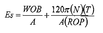
- WOB weight on bit
- ROP rate of penetration
- rotary speed bit speed
- top drive speed top drive speed
- downhole motor speed and torque on a drillstring or on a bit.
- WOB weight on bit
- N rpm's of a rig's rotary
- T the torque at the bit
- ROP rate of penetration
- A wellbore (or bit) cross-sectional area.
- the mechanical efficiency of drilling was then estimated by comparing actual specific energy required to drill an interval with the minimum expected specific energy needed to drill that interval.
- Pessier et al analyzed values of various parameters (actual specific energy, minimum specific energy, energy efficiency, and bit-specific coefficient of sliding friction) with respect to ROP under different situations (e.g., different bits, different WOB's, different RPM's, different hydraulics, and under atmospheric and hydrostatic pressure).
- a method for facilitating a wellbore operation with a wellbore apparatus comprising the steps of acquiring data with sensor apparatus at at least two points along said wellbore apparatus, the method further comprising the step of using the acquired data to calculate a mechanical specific energy value for each of said at least two points along said wellbore apparatus and monitoring said mechanical specific energy values.
- the results of monitoring mechanical specific energy at points along the wellbore apparatus preferably, gives an indication of increased friction and a location of the cause of the increased friction.
- the acquired data may also be used to alter, change, improve, or optimize wellbore operations.
- the method optimizes the bit (or mill) replacement process.
- the method facilitates analysis and detection of downhole problems related to energy loss, locating a cause of energy loss, eliminating correctly operating systems as a cause of energy loss and providing real-time confirmation that chosen solutions do not negatively impact components of a drilling system, e.g. bits (or mills), bottomhole assemblies ("BHA”), downhole (mud) motors, and drill strings.
- the wellbore apparatus comprises a string of drill pipe and a tool connected in or to the string of drill pipe, wherein the data is acquired during rotation of at least one of the string of drill pipe and the tool.
- the wellbore apparatus comprises a string of casing and a tool connected in or to the string of casing, wherein the data is acquired during rotation of at least one of the string of casing and the tool.
- the wellbore apparatus comprises coiled tubing and a tool connected in or to the coiled tubing, wherein the data is acquired during rotation of at least one of the coiled tubing and the tool.
- Coiled tubing is any long piece tubing, which has been, for example, uncoiled from a reel and injected into a well for carrying out operation in the wellbore, such as extending the reach of the wellbore, side tracking and obtaining data from the wellbore.
- Coiled tubing may be used in well intervention and this method of the invention can be used in such well intervention methods.
- At least one of the at least two points is located at or close to one or more of: the surface of the wellbore; at the top of the wellbore apparatus; at the bottom of the wellbore; at a tool located in or on the wellbore apparatus; between surface and the bottom of the wellbore; and at the bottom of the wellbore apparatus.
- MSE is calculated at or close to the drill bit, anywhere or at multiple locations along the drill string or coiled tubing, and at the surface close to the rotary table or top drive.
- the tool such as a drilling bit, milling bit, reamer, under-reamer etc.
- the point at the bottom of the drill string is on the Bottom Hole Assembly.
- said sensor apparatus is located at at least one of each of said at least two points along said wellbore apparatus.
- the surface mechanical specific energy is calculated using surface measured inputs and bit mechanical specific energy is calculated using downhole measured inputs actually measured downhole.
- the values for mechanical specific energies are calculated using surface measured inputs.
- the wellbore operation is any of: drilling; milling; reaming; hole-opening; casing drilling; drilling with a downhole motor; coiled tubing operations; junk milling; milling-drilling; and managed pressure drilling.
- Drilling is carried out using a top drive or rotary table to rotate the drill string.
- a downhole motor such as a mud motor may be used instead of or in addition to rotation of the drill string by the top drive or rotary table to rotate the drill bit, milling tool or other tool located on the end of the drill dtring.
- the acquired data includes data indicative of any of: Weight On Bit; Rate Of Penetration; bit rotational speed; torque at a bit; torque at surface; rotary rotational speed; and bit cross-sectional area.
- the method further comprises a database comprising a bank of mechanical specific energy values for points along the wellbore apparatus.
- said database stores threshold values of mechanical specific energy values for points along the wellbore apparatus. For example, a threshold value for a PDC drill bit drilling through a particular type of formation such as rock.
- an alarm is activated in response to at least one of a mechanical specific energy values which exceed a predetermined threshold.
- the alarm may be at least one of the following: visual, audible, vibration based or any other suitable means to alert the user there may be a problem.
- the monitored mechanical specific energy values are used in a control system for controlling the wellbore operation, the method further comprising the step of controlling the wellbore operation based on said calculated mechanical specific energy values.
- the control system comprises a computer readable medium having instructions for any of: providing an alarm if a pre-set value for a mechanical specific energy is exceeded; controlling system apparatuses used in the wellbore operation; conducting a diagnostic test of any of said system apparatuses; storing calculated values; and controlling the wellbore operation to execute a higher level strategy.
- the step of monitoring the mechanical specific energy values are analyzed for indicating a problem with the wellbore operation.
- the method further comprises the step of determining which part of the wellbore apparatus has the problem.
- the method further comprises the step of providing confirmation that there is not an impediment to the wellbore operation.
- the method further comprises the step of analyzing said mechanical specific energies values to determine whether there is a change in energy consumption by the wellbore operation.
- the method further comprises the step of calculating the difference of the specific energy values for the at least two points along the wellbore apparatus.
- the mechanical specific energy between, for example, a drill string and a drill bit, the difference may be an increase.
- At least one of the mechanical specific energy values is calculated using Teale's definition of mechanical specific energy. This is particularly useful for calculating mechanical specific energy of a drill bit.
- the present invention discloses methods for determining localized differentiated mechanical specific energy parameters: surface mechanical specific energy; drillstring mechanical specific energy; and bit (or mill or other apparatus) mechanical specific energy.
- Equation II The two terms within the parentheses in Equation II are referred to here as "WOB term” (left one with WOB) and “torque term” (right one with T). In general, the magnitude of the torque term is usually much larger than the WOB term.
- the wellbore operation is a hole-opening operation and mechanical specific energies are calculated using a volume of drilled-out material.
- the wellbore operation is a reaming operation for reaming an already-produced wellbore producing a reamed wellbore, and values for mechanical specific energies calculated for the already-produced wellbore are compared to values for mechanical specific energies calculated for the reaming operation.
- the wellbore operation is a milling operation and values of calculated mechanical specific energies are monitored and processed to indicate any of: a change in mechanical specific energy as an item is first encountered by a mill; a change or trend in mechanical specific energy behaviour as increasing amounts of material are milled; a drop in mechanical specific energy as a mill exits an item being milled; and a value of mechanical specific energy that indicates a mill is encountering formation outside an item being milled.
- the wellbore operation is managed pressure drilling and values of calculated mechanical specific energies are monitored and processed to indicate any of: a pressure differential in a wellbore; less energy required during drilling; and confirmation that drilling is progressing as desired.
- the present invention also provides a computer-readable media having computer executable instructions for facilitating an wellbore operation in a wellbore with a wellbore apparatus, the computer-executable instructions performing the following steps: acquiring data with sensor apparatus at at least two points along said wellbore apparatus; and calculating a mechanical specific energy value for each of said at least two points along said wellbore apparatus using the acquired data.
- the computer-readable media further comprises a database of threshold mechanical specific energy values.
- the computer-readable media further comprises computer-executable instructions to trigger an alarm in response to crossing a threshold mechanical specific energy value stored in the database.
- the computer-readable media further comprises computer-executable instructions to monitor the mechanical specific energy values.
- the present invention also provides a computing unit configured to read and perform the computer-executable instructions on computer-readable media of the present invention.
- the computing unit further comprises apparatus to store mechanical specific energy values.
- the computing unit further comprises display apparatus to display at least one of the mechanical specific energy values.
- the computing unit further comprises display apparatus to display pictorially at least one of the mechanical specific energy values.
- the computing unit further comprises transmitting to receiving apparatus signals indicative of the value of each of the calculated mechanical specific energies.
- Surface mechanical specific energy can be calculated using surface inputs, e.g. surface-measured torque, WOB, and/or ROP.
- Bit mechanical specific energy can be calculated using downhole measured inputs, e.g. downhole measured torque and/or other downhole measured parameters or, in one aspect, using surface measured inputs, e.g. WOB, ROP, bit RPM (surface measured); i.e., where downhole measured values are not available and/or where they do not impact calculated mechanical specific energy values.
- Downhole measured means "actually measured” downhole (e.g. measured torque of a downhole motor) or it means derived from other downhole measured values (e.g. torque derived from mud motor parameters) and/or may mean "derived from” surface measured data, e.g. torque as determined with measurements from a measured pressure differential across a downhole motor.
- Bit mechanical specific energy is calculated using available downhole data and, in certain aspects, is the same as downhole mechanical specific energy.
- bit mechanical specific energy uses a minimum of required downhole inputs, e.g. enough key values to quantify the mechanical specific energy, e.g. only downhole measured torque, only downhole measured WOB or only downhole measured bit RPM.
- the use of localized differentiated mechanical specific energy values enhances the diagnostic potential and efficiency of the diagnosis of bit vs. drillstring mechanics; indicates more clearly than certain prior art systems the sources of data, i.e. where energy loss is occurring, e.g. loss occurring at the bit, (or mill or other apparatus) between the bit and the surface, or at any point, in a drillstring or for any tool or apparatus in a drillstring or other string; provides more understandable interpretation and presentation of data on site at a rig; and provides for the use of data from both downhole and from the surface to generate more accurate calculations.
- a determination of drillstring (or other string) mechanical specific energy is made by calculating the difference between surface mechanical specific energy and bit mechanical specific energy.
- FIG 1A shows a drilling apparatus 10 drilling a wellbore WB.
- the drilling apparatus 10 has a bottom hole assembly BHA comprising a bit B and a mud motor M which is connected to coiled tubing CT dispensed from a reel R which extends through an injector I into and through a BOP and a wellhead WH.
- Fluid F is pumped down through the coiled tubing CT to the bottom hole assembly BHA by pumps P1, P2.
- Cuttings CB flow up an annulus A with fluid F which exit the coiled tubing through the bit B.
- Sensors S provide signals indicative of various parameters, including, e.g., WOB, ROP, torque, bit rotation speed, and bit cross-section area.
- WOB, ROP, and/or torque can be measured by sensor(s) S at the injector I and/or downhole.
- Bit rotational speed (zero at the surface, by definition) is measured downhole.
- the sensors are in communication with a system CS (e.g. a computer system or systems, PLC's, and/or DSP's).
- the system CS calculates differentiated mechanical specific energies; e.g. three different mechanical specific energies - drillstring, bit, and surface.
- Any suitable known downhole sensors can be used (for the system and method of Figure 1A and/or for any system and method disclosed herein), including, but not limited to, those disclosed in U.S. Patents 6,839,000 ; 6,564,883 ; 6,429,784 ; 6,247,542 ; and in the references cited therein, all incorporated fully herein for all purposes.
- a driller DR views a display (screen and/or strip chart) DS which indicates in real time the value of and change (if any) in drillstring mechanical specific energy, bit mechanical specific energy, and surface mechanical specific energy.
- the system may provide and the display may also display results post-event, not in real time.
- the system CS is programmed to produce an alarm (audio and/or visual) when a certain level of mechanical specific energy is approached or exceeded.
- bit mechanical specific energy is acceptable, but severe drillstring vibrations cause high energy losses in the BHA and in the drillstring.
- the driller DR in viewing the display DS (e.g.
- bit mechanical specific energy is and has remained acceptable, it is clear that there is no problem in the bit and bit repair or replacement is ignored as an option for solving the problem.
- the driller DR continues to monitor the display DS to insure that the attempted solution has not negatively impacted bit operation (i.e., he monitors the display to see if bit mechanical specific energy remains at an acceptable level).
- FIG. 1C is a block diagram indicating an operation of the apparatus shown in Figure 1A and programming for the control system 50.
- a driller DR in the scenario described above may or may not suspect a drillstring energy loss is occurring, as opposed to a problem at the bit or at the surface. If the driller does suspect that there is only a drillstring problem, he would look at individual pieces of data, e.g. he could compare surface torque and downhole torque (e.g. derived from a pressure differential across the mud motor). Finally, he infers further that addressing the drillstring energy loss is required to solve the problem.
- the systems and methods in accordance with the present invention take the guesswork and inference out of the solution process and provide an accurate isolation of a problem's cause and an indication of probable solutions.
- the system CS e.g. any suitable computer, computer system, or programmable system
- the system CS is programmed to monitor mechanical specific energy in real time and to take certain actions if a pre-set level for any mechanical specific energy value is exceeded [and to take action if a mechanical specific energy value goes up dramatically or "spikes", yet does not exceed pre-set value or goes down, which might indicate a change in the formation being drilled if controllable drilling parameters (e.g. WOB, RPM) were not changed].
- the system CS is programmed to control any drilling parameter or set of parameters (e.g. one or some in any combination, of WOB, ROP, torque and/or bit speed).
- the computer CS is programmed to perform one, some, or all of the following actions:
- Figure 2 illustrates one system 100 and method in accordance with the present invention which has sensors 51 - 57 for providing data for calculating WOB, ROP, bit speed and torque. As shown, Figure 2 has a top drive 72, a rotary drive 74 and a downhole motor 70 to indicate that any of these drive systems may be used with systems and methods in accordance with the present invention.
- a drillstring 20 extending down from a rig 12 into a wellbore 36 in an earth formation 24 has a bit 22 on a bottom hole assembly 16 at the wellbore bottom.
- Drilling fluid 26 flows from a tank or pit 28 pumped by a pump system 38 through a piping system 40 down the drillstring 20 and returning up an annulus 25 flowing in a line 42 back to the tank 28.
- a control system 50 includes a computer CP with a display 60, a printer 62 and a printout 64.
- Input devices 58 receive data signals from the sensors 51 - 57 which are in communication with the computer via wire, cable and/or wireless communication.
- sensors may provide signals indicative of the following: WOB, at the surface from a sensor or a drill line anchor or downhole from a sensor 51 of an MWD unit; torque, at the surface from a sensor 52 of the rotary drive 74 or from a sensor 55 of the top drive 72, or downhole from the sensor 51; ROP, at the surface from a sensor 53 on an encoder ED of a drawworks DR (shown schematically) or from the sensor 51; and bit rotational speed at the surface from a sensor 55 in the top drive or from a sensor 54 in the rotary drive or downhole from the sensor 51; or from a sensor 57 in the motor 70.
- the computer CP calculates three differentiated mechanical specific energies, drillstring mechanical specific energy, bit mechanical specific energy, and surface
- the drilling operation control outputs from the computer CP are provided to various controllers and control systems C1 - C6 which control drill line payout (brake control and/or drawworks motors control); a rotary table (control bit speed); a top drive (control bit speed) mud pumps (pump rate control) downhole drilling systems, and/or rotary steerable systems.
- a new bit 22 is tripped into the wellbore and the drillstring 20 is run down to the wellbore bottom.
- the driller enters into the computer CP target ROP, bit rotational speed, drilling fluid pump rate, and WOB.
- the control system 50 then prepares to collect data related to all the drilling parameters to be measured and monitored and calculates and displays the three mechanical specific energies.
- the system 50 proceeds to determine a background mechanical specific energy level with drilling at "safest" conditions and determines that the entire allowable operating range for WOB, RPM, torque and ROP is within safe limits.
- WOB and bit RPM are directly controlled by the driller. Torque and ROP are resultants of this control, but can also be controlled, for example, by adjusting WOB and/or rotational speed to alter the resultant torque and ROP's.
- the driller then starts drilling with the target ROP, WOB, RPM, and pump rate.
- the system 50 informs the driller that the drilling process in progress is acceptable. In one particular scenario, the system 50 then detects an increase in bit mechanical specific energy, informs the driller that an abnormal event is occurring, and begins a diagnostic process.
- the system 50 moves all control parameters to a safe (or safest) value (e.g. to values at which bit balling will not occur), e.g. minimum WOB, maximum RPM, and maximum drilling fluid pump rate.
- a safe (or safest) value e.g. to values at which bit balling will not occur
- the system 50 controls equipment directly or sends set points to individual devices' controllers.
- the bit mechanical specific energy then returns to an acceptable or baseline value and the system 50 concludes that bit balling had been occurring when the drilling operation was at the original target values the driller had been using.
- the system 50 then informs personnel, e.g. the driller and/or the company man, that bit balling has been detected and the system 50 offers two possible course of action: 1. replace the bit; 2. let the system 50 attempt to find a maximum ROP at which balling will not occur. In the event option 2.
- the rig personnel can decide if the calculated ROP is acceptable for further drilling.
- the control system resumes drilling at the determined safe values of the drilling parameters (e.g. those at which bit balling is least likely to occur) and then manipulates ROP, RPM, WOB and pump rate to achieve maximum ROP while seeing that bit mechanical specific energy is maintained at or below "no balling" values.
- Figure 3 illustrates a wellbore hole-opening operation 100u (or "under-reaming") in which the diameter of an already-drilled hole 102 is increased to a hole 104 with a wider diameter with an assembly 106 including an under-reamer 108 which has expandable arms 110, with cutters 112 on the end, and a drill bit 114.
- the drill bit 114 can remove fill or cave-in material and/or can ream the hole back to gauge.
- mechanical specific energies are calculated using a volume of material, e.g. rock or formation of the outer ring of the hole 104 that is drilled out (i.e. between the original hole size of the hole 102 and the new hole size of the hole 104).
- the values for mechanical specific energies determined in drilling the original hole are used for comparison during the hole-opening. Abnormally high values may indicate that the under-reamer 108 (and possibly the drill bit 104) is drilling a larger-than-expected area of rock (for example, hole totally caved in) or that the under-reamer has mechanical problems, worn bit, etc.
- the effective "bit diameter" for mechanical specific energy calculations is the diameter of the hole opener's cutters.
- an under-reamer can be run in a hole separate from or without a bit.
- Reaming is a method of "drilling again" an already-drilled hole section; e.g., as shown in Figure 4 , a drilling system 120 with a bit 122 is reaming a hole 124 in a formation 128 to a reamed hole diameter of a new hole 126. Often, this is pumping and rotating the drill string down through a section to insure that the hole has stayed the desired gauge (i.e. drilled) size. This is often a common practice, where each new section (stand or joint) is reamed before stopping to make a connection.
- an under-gauge hole is reamed (for example, a previously used bit had gage wear around the outside and did not drill a full size hole), where reaming drills out the outer diameter that was missed the first time.
- Reaming is normally a low-energy process, since minimal rock is removed.
- some situations, such as drilling an under-gauge hole can be challenging, due to drill bits being designed for drilling out a full-cross-section of rock, as opposed to drilling only the outer ring and encountering high side forces from the sloped sides of the hole.
- mechanical specific energies are computed by the same methods used for drilling as described above (i.e.
- the calculated values for reaming to the new hole 126 are compared to those obtained (and stored in memory of a system, as can be done with any system in accordance with the present invention with any measurements, inputs, and/or calculated mechanical specific energies) during the original drilling procedure for drilling the hole 124.
- the values for reaming should be considerably lower than those of the original drilling, due to the minimal rock being removed. If they are high, then some downhole problem, such as pinching in under-gauge hole, may be indicated. These high values may indicate a problem with the drilling process (during reaming), or they may indicate a problem resulting from the original drilling process (such as the presence of under-gauge hole).
- Casing drilling is a process whereby a hole 130 is drilled using the casing which will be cemented into the drilled hole 130 in a formation 136 without using a drillstring to drill (in one aspect without any additional trips for casing the hole).
- a bit 134 (or other hole maker) used to make the hole may be wireline retrievable inside the casing 132, or it may be a disposable and/or drillable bit or hole maker attached to the end of the casing 132.
- mechanical specific energies are calculated in principle as described above for drilling. Methods using mechanical specific energies calculated in accordance with the present invention for casing drilling procedures are useful as follows:
- drilling is carried out with a mud motor 140 on the end of coiled tubing 142.
- Downhole data is obtained via MWD ("measurement-while-drilling") pulsing or a cable 144 run inside the coiled tubing 142 (providing higher resolution data).
- the coiled tubing 142 is provided from a reel system 146 through a BOP 143 and a wellhead 148 into a wellbore 145 in an earth formation 147.
- the mud motor 140 is part of a typical downhole bottom hole assembly 149.
- Coiled tubing drilling can provide faster tripping speed, no connections (hence no stopping pump and circulation, and better downhole pressure control) and an option for higher resolution downhole data.
- Coiled tubing can have lower strength of the tubing (especially in torsion), less weight available to put on bit, smaller pipe internal diameter (limiting flow rates and hydraulics), no option to rotate pipe from surface, and smaller bit sizes.
- Coiled tubing drilling is often used for niche applications, such as re-drilling a producing zone for less damage or for staying within a thin formation interval.
- mechanical specific energies are calculated as described above for drilling. Such methods may provide the following additional benefits:
- Milling is the process of milling away an object in a wellbore or milling out a section of a casing (or tubular) wall and can include drilling a formation, e.g. drilling enough of an adjacent formation so that a conventional drilling assembly can be used to continue drilling into the formation.
- Figures 7A - 7D illustrate a milling process using methods in accordance with the present invention.
- a mill 150 either releasably attached to or separate from a whipstock 152 (or other mill diverter, mill guide, or turner) is lowered into a wellbore 154 which is cased with casing 156.
- the mill 150 mills a hole or "window" 158 in the casing 156.
- the mill 150 mills through the casing 156 (see Figure 7B ) it begins to cut away earth from an earth formation 162 adjacent the casing 156. If it is allowed to proceed (see Figure 7D ) the mill 150 mills a hole 164 in the earth formation 162.
- the methods of the present invention are useful in milling procedures and in milling/drilling or milling-and-drill procedures, e.g., in the system and methods of U.S.
- a mill In a milling process, from start to finish, a mill often does not drill a homogenous material, but rather a continually-changing mixture of mud (i.e. open space), steel, cement and/or formation.
- a variety of feedback items are of value during milling; e.g. indications that the process is progressing as desired; an indication that the casing (or tubular) wall is first penetrated; and an indication that the mill has fully exited the casing (or tubular) and is totally into the formation.
- mechanical specific energies are calculated in a manner similar to that for drilling as described above. The bit diameter used is the mill diameter. Calculated mechanical specific energies indicate the rate of energy used per rate of milling.
- FIGS. 8A and 8B show a mill 170 in casing 172 in a wellbore (not shown) milling a piece of junk 174 (shown schematically).
- the junk 174 may be a packer or other item that is to be milled out.
- the mill does not drill a homogenous material, but rather an unknown (at the surface) mixture of components (metal, plastic, etc.), cuttings and/or possibly formation fill, such as sand.
- Some additional feedback items that are provided during milling methods in accordance with the present invention using mechanical specific energies calculated in accordance with the present invention during such milling methods are indications that the process is progressing as desired and whether the mill is milling part of the junk or is milling something else, e.g. casing, which is undesirable.
- the mechanical specific energies for such methods are calculated in a manner similar to that for drilling as described above.
- the mill diameter is the bit diameter. Calculated mechanical specific energies in these milling situations measure the rate of energy used per rate of milling. Since a mill can encounter many conditions (which are unknown at the surface), patterns (or signatures) of mill behaviour and of key events are developed over time and stored in a searchable, retrievable database. Some examples of these are:
- Managed pressure drilling includes drilling with downhole pressure control provided by dynamic control of the annulus pressure in a wellbore.
- UnderBalanced Drilling is a subset of managed pressure drilling whereby the downhole pressure is managed so that it is below the formation pressure of a formation through which the wellbore extends and formation fluids are allowed to flow to the surface.
- Figure 9 illustrates use of methods in accordance with the present invention in an underbalanced drilling operation.
- Mud pumps 180 provide drilling fluid under pressure down a drillstring 182 to a drill bit 184 at a pressure sufficiently low so that formation fluids 186 can flow from a formation 188 into an annulus 189 around the bit 184 and drillstring 182 up to an exit line 183.
- a choke system 181 controls flow to a tank or reservoir 191 which has an upper flare 192 for flaring gas and a lower line 193 through which fluid flows to a mud pit 194 which is in fluid communication via a line 195 with the mud pumps 180.
- a BOP 196 is used on the wellbore 197.
- Equation II (see above) or Teale's definition are not used for calculating mechanical specific energy; e.g. there are many rigs where the drillstring rotational torque is not available in ft-lbs.
- An example of this is the commercially available M/D Totco Rotary Torque System, an hydraulic system for mechanical rigs. This system measures deflection in the chain driving the rotary table and outputs this deflection as an hydraulic pressure in psi. If the torque is not available in ft-lbs, then a value of mechanical specific energy in Kpsi cannot be computed. However, being able to compute an equivalent value that is proportional to what would be the value of mechanical specific energy still has value in a relative sense, as many applications of mechanical specific energy use a trend in value and/or do not require an absolute value.
- Equation III In certain methods in accordance with the present invention where torque is not available in ft-lbs, Equation III (see above) is used. While units are shown above for Equation III, their use is not required for successful results with this method, as it still produces usable results with no units or even erroneous units (for example, conversion errors), as long as the values are proportional to the correct values. This is a robust solution for many typical rig conditions.
- the elimination of the constants from Equation II (480 and 1000) is similarly arbitrary. Methods using Equation III arbitrarily modify the Kadj factor until the resulting mechanical specific energy "makes sense" (i.e.
- Equation III calculations provide most of the value of mechanical specific energy for less computational effort. However, Equation III calculations do not have a meaningful absolute value (i.e.
- Equation III will work with any (positive) value of Kadj, judicious selection of Kadj will expand the general use value of these methods of determining mechanical specific energy.
- the present invention therefore in at least certain but not all preferred embodiments provides: a method for a wellbore operation with a wellbore system, the method including: acquiring with sensor systems data corresponding to a plurality of parameters, said data indicative of values for each parameter of said plurality of parameters, each parameter corresponding to part of the wellbore system; based on said data, calculating a mechanical specific energy value for each of a plurality of mechanical specific energies each related to a mechanical specific energy for a part of the wellbore system; and monitoring the value of each of the mechanical specific energies.
- Such a method may include one or some, in any possible combination, of the following: wherein the wellbore operation is any of drilling, milling, reaming, hole-opening, casing drilling, drilling with a downhole motor, coiled tubing operations, junk milling, milling-drilling, and managed pressure drilling; wherein the plurality of parameters includes any of WOB, ROP, bit rotational speed, torque at a bit, torque at surface, rotary rotational speed, and bit crosssectional area; providing calculated mechanical specific energy values to alarm apparatus; providing an alarm with the alarm apparatus based on the values of the mechanical specific energies; providing calculated mechanical specific energy values to a control system for controlling the operation, and controlling the operation based on said calculated mechanical specific energy values; monitoring the values of calculated mechanical specific energy values and analyzing said values for indicating a problem with the wellbore operation; determining at least one solution j(or a plurality of possible solutions) to the problem based on the values of the calculated mechanical specific energy; providing confirmation that the at least one solution (or
- the plurality of mechanical specific energies includes surface, drillstring, and bit mechanical specific energy; wherein surface mechanical specific energy is calculated using surface measured inputs and bit mechanical specific energy is calculated using downhole measured inputs actually measured downhole; wherein the values for mechanical specific energies are calculated using surface measured inputs; wherein drillstring mechanical specific energy is calculated using a difference between surface mechanical specific energy and bit mechanical specific energy; wherein the wellbore operation is an operation with a rotating bit (or reamer or mill) and values for the mechanical specific energies are calculated according to the equation for Teale's definition of mechanical specific energy; wherein the wellbore operation is an operation with a rotating bit and values for the mechanical specific energies are calculated according to Equation II; wherein the wellbore operation is an operation with a rotating bit (or reamer or mill) and values for the mechanical specific energies are calculated according to Equation III; providing in real time a display of calculated values of the plurality of mechanical specific energies; wherein a control system
- the present invention therefore, in at least certain but not all preferred embodiments provides a computer-readable media having computer executable instructions for a wellbore operation with a wellbore system, the computer-executable instructions performing the following steps: receiving from sensor systems data corresponding to a plurality of parameters, said data indicative of values for each parameter of said plurality of parameters, each parameter corresponding to part of the wellbore system, calculating, based on said data, a mechanical specific energy value for each of a plurality of mechanical specific energies each related to a mechanical specific energy for a part of the wellbore system, and transmitting to receiving apparatus signals indicative of the value of each of the calculated mechanical specific energies; and, in certain aspects, the computer-readable media wherein the receiving apparatus is a display system; and, in one aspect, a computing unit with such computer-readable media, the computing unit configured to read and perform the computer-executable instructions.
Landscapes
- Geology (AREA)
- Life Sciences & Earth Sciences (AREA)
- Engineering & Computer Science (AREA)
- Mining & Mineral Resources (AREA)
- Geochemistry & Mineralogy (AREA)
- Fluid Mechanics (AREA)
- Environmental & Geological Engineering (AREA)
- General Life Sciences & Earth Sciences (AREA)
- Physics & Mathematics (AREA)
- Chemical & Material Sciences (AREA)
- Analytical Chemistry (AREA)
- Earth Drilling (AREA)
- Operation Control Of Excavators (AREA)
- Geophysics And Detection Of Objects (AREA)
- Perforating, Stamping-Out Or Severing By Means Other Than Cutting (AREA)
- Testing Or Calibration Of Command Recording Devices (AREA)
Claims (34)
- Verfahren zum Erleichtern einer Bohrlochoperation mit einer Bohrlochvorrichtung, wobei das Verfahren den Schritt des Erfassens von Daten mit einer Sensorvorrichtung an wenigstens zwei Punkten längs der Bohrlochvorrichtung umfasst, wobei das Verfahren ferner die Schritte des Verwendens der erfassten Daten zum Berechnen eines Wertes der spezifischen mechanischen Energie für jeden der wenigstens zwei Punkte längs der Bohrlochvorrichtung und des Überwachens der Werte der spezifischen mechanischen Energie umfasst.
- Verfahren nach Anspruch 1, wobei die Bohrlochvorrichtung einen Bohrrohrstrang und ein Werkzeug, das in oder mit dem Bohrrohrstrang verbunden ist, umfasst, wobei die Daten während der Drehung dcs Bohrrohrstrangs und/oder des Werkzeugs erfasst werden.
- Verfahren nach Anspruch 1, wobei die Bohrlochvorrichtung einen Futterrohrstrang und ein Werkzeug, das in oder mit dem Futterrohrstrang verbunden ist, umfasst, wobei die Daten während der Drehung des Futterrohrstrangs und/oder des Werkzeugs erfasst werden.
- Verfahren nach Anspruch 1, wobei die Bohrlochvorrichtung eine Rohrwendel und ein Werkzeug, das in oder mit der Rohrwendel verbunden ist, umfasst, wobei die Daten während der Drehung der Rohrwendel und/oder des Werkzeugs erfasst werden.
- Verfahren nach einem vorhergehenden Anspruch, wobei sich wenigstens einer der wenigstens zwei Punkte bei einem oder mehreren oder in der Nähe eines oder mehrerer der folgenden Bereiche befindet: Oberfläche des Bohrlochs; Oberseite der Bohrlochvorrichtung; Boden des Bohrlochs; Werkzeug, das sich in oder an der Bohrlochvorrichtung befindet; zwischen der Oberfläche und dem Boden des Bohrlochs; und Unterseite der Bohrlochvorrichtung.
- Verfahren nach einem vorhergehenden Anspruch, wobei sich die Sensorvorrichtung bei wenigstens einem der wenigstens zwei Punkte längs der Bohrlochvorrichtung befindet.
- Verfahren nach einem vorhergehenden Anspruch, wobei die Bohrlochoperation eine der Folgenden ist: Bohren; Mahlen; Ausräumen; Lochöffnen; Futterrohrbohren; Bohren mit einem Bohrlochmotor; Rohrwendeloperationen; Abfallmahlen; Mahlen/Bohren; und gesteuertes Druckbohren.
- Verfahren nach einem vorhergehenden Anspruch, wobei die erfassten Daten Daten enthalten, die einen der folgenden Werte angeben: Gewicht auf Bohrerspitze; Eindringrate; Bohrerspitzendrchzahl; Drehmoment bei einer Bohrerspitze; Drehmoment bei einer Oberfläche; Drehzahl; und Bohrerspitzenquerschnittsfläche.
- Verfahren nach einem vorhergehenden Anspruch, das ferner eine Datenbank enthält, die eine Bank aus Werten der spezifischen mechanischen Energie für Punkte längs der Bohrlochvorrichtung enthält.
- Verfahren nach Anspruch 9, wobei die Datenbank Schwellenwerte für Werte der spezifischen mechanischen Energie für Punkte längs der Bohrlochvorrichtung speichert.
- Verfahren nach einem vorhergehenden Anspruch, wobei in Reaktion auf wenigstens einen der Werte der spezifischen mechanischen Energie, die einen vorgegebenen Schwellenwert überschreiten, ein Alarm aktiviert wird.
- Verfahren nach einem vorhergehenden Anspruch, wobei die überwachten Werte der spezifischen mechanischen Energie in einem Steuersystem verwendet werden, um die Bohrlochoperation zu steuern, wobei das Verfahren ferner den Schritt des Steuerns der Bohrlochoperation anhand der berechneten Werte der spezifischen mechanischen Energie umfasst.
- Verfahren nach einem vorhergehenden Anspruch, wobei in dem Schritt des Überwachens der Werte der spezifischen mechanischen Energie diese Werte analysiert werden, um ein Problem in der Bohrlochopcration anzugeben.
- Verfahren nach Anspruch 13, das ferner den Schritt des Bestimmens wenigstens einer Lösung für das Problem anhand der Werte der spezifischen mechanischen Energie umfasst.
- Verfahren nach Anspruch 14, das ferner den Schritt des Bestimmens, in welchem Teil der Bohrlochvorrichtung ein Problem besteht, umfasst.
- Verfahren nach einem vorhergehenden Anspruch, das ferner den Schritt des Bereitstellens einer Bestätigung, dass keine Behinderung für die Bohrlochoperation vorhanden ist, umfasst.
- Verfahren nach einem vorhergehenden Anspruch, das ferner den Schritt des Analysierens der Werte der spezifischen mechanischen Energie umfasst, um zu bestimmen, ob eine Änderung des Energieverbrauchs durch die Bohrlochoperation erfolgt ist.
- Verfahren nach einem vorhergehenden Anspruch, das ferner den Schritt des Berechnens der Differenz der Werte der spezifischen Energie für die wenigstens zwei Punkte längs der Bohrlochvorrichtung umfasst.
- Verfahren nach einem vorhergehenden Anspruch, wobei wenigstens einer der Werte der spezifischen mechanischen Energie unter Verwendung der Teale-Funktion der spezifischen mechanischen Energie berechnet wird:
- Verfahren nach einem vorhergehenden Anspruch, wobei wenigstens einer der mechanischen spezifischen Energiewerte unter Verwendung der folgenden Gleichung berechnet wird:

wobei:MSE = spezifische mechanische Energie, KpsiEffb = Bohrerspitzen-WirkungsgradWOB = Gewicht auf Bohrerspitze, lbsD = Bohrerspitzendurchmesser, ZollNb = Bohrerspitzendrehzahl, min-1T = Bohrstrang-Drehmoment, Fuß-IbROP = Eindringrate, Fuß/Std - Verfahren nach einem vorhergehenden Anspruch, wobei wenigstens einer der Werte der spezifischen mechanischen Energie unter Verwendung der folgenden Gleichung berechnet wird:

wobei:MSE = spezifische mechanische EnergieKadj = EinstellfaktorEffb = Bohrerspitzen-WirkungsgradD = Bohrerspitzendurchmesser, ZollNb = Bohrerspitzendrehzahl, min-1Trel = relatives Maß des Bohrstrang-Drehmoments, Einheiten pro VorrichtungROP = Eindringrate, Fuß/Std. - Verfahren nach einem vorhergehenden Anspruch, das ferner den Schritt des Berechnens von Werten der spezifischen mechanischen Energie in Echtzeit umfasst.
- Verfahren nach einem vorhergehenden Anspruch, das ferner den Schritt des Anzeigens von Werten der spezifischen mechanischen Energie in Echtzeit umfasst.
- Verfahren nach einem vorhergehenden Anspruch, wobei die Bohrlochoperation eine Lochöffnungsoperation ist und spezifische mechanische Energien unter Verwendung eines Volumens von ausgebohrtem Material berechnet werden.
- Verfahren nach Anspruch 24, wobei wenigstens einer der Werte der spezifischen mechanischen Energie unter Verwendung der folgenden Gleichung berechnet wird:

wobei:A104 = Fläche des neuen Lochs,A102 = Fläche des ursprünglichen Lochs,Es = spezifische mechanische Energie, KpsiWOB = Gewicht auf Bohrerspitze, lbsN = Drehzahl, min-1T= Bohrstrang-Drehmoment, Fuß-lbROP = Eindringrate, Fuß/Std. - Verfahren nach einem vorhergehenden Anspruch, wobei die Bohrlochoperation eine Ausräumoperation zum Ausräumen eines bereits erzeugten Bohrlochs ist, um ein ausgeräumtes Bohrloch zu erzeugen, und Werte für spezifische mechanische Energien für das bereits erzeugte Bohrloch mit Werten für spezifische mechanische Energien, die für die Ausräumoperation berechnet wurden, verglichen werden.
- Verfahren nach einem vorhergehenden Anspruch, wobei die Bohrlochoperation eine Mahloperation ist und Werte berechneter spezifischer mechanischer Energien überwacht und verarbeitet werden, um eines der folgenden Ereignisse anzugeben: Änderung der spezifischen mechanischen Energie, wenn ein Element erstmals auf eine Mühle trifft; Änderung oder Streben des Verhaltens der spezifischen mechanischen Energie, wenn zunehmende Materialmengen gemahlen werden; Abnahme der spezifischen mechanischen Energie, wenn eine Mühle ein gemahlenes Element ausstößt; und Wert der spezifischen mechanischen Energie gibt an, dass eine Mühle auf eine Formation außerhalb eines gemahlenen Elementes trifft.
- Verfahren nach einem vorhergehenden Anspruch, wobei die Bohrlochoperation ein gesteuertes Druckbohren ist und Werte von berechneten spezifischen mechanischen Energien überwacht und verarbeitet werden, um eines der Folgenden anzugeben: Druckdifferenz in einem Bohrloch; die Tatsache dass während des Bohrens weniger Energie erforderlich ist; und Bestätigung, dass das Bohren wie gewünscht voranschreitet.
- Recheneinheit, die konfiguriert ist, um computerausführbare Befehle auf einem computerlesbaren Medium zu lesen und auszuführen, um eine Bohrlochoperation in einem Bohrloch mit einer Bohrlochvorrichtung zu erleichtern, wobei die computerausführbaren Befehle die folgenden Schritte ausführen: Erfassen von Daten mit einer Sensorvorrichtung an wenigstens zwei Punkten längs der Bohrlochvorrichtung; und Berechnen eines Wertes der spezifischen mechanischen Energie für jeden der wenigstens zwei Punkte längs der Bohrlochvorrichtung unter Verwendung der erfassten Daten.
- Recheneinheit nach Anspruch 29, die ferner eine Datenbank für Schwellenwerte für Werte der spezifischen mechanischen Energie umfasst.
- Recheneinheit nach Anspruch 30, die ferner computerausführbare Befehle enthält, um in Reaktion auf einen Durchgang durch einen Schwellenwert für die Werte der spezifischen mechanischen Energie, der in der Datenbank gespeichert ist, einen Alarm auszulösen.
- Recheneinheit nach Anspruch 30, die ferner computerausführbare Befehle umfasst, um die Werte der spezifischen mechanischen Energie zu überwachen.
- Recheneinheit nach einem der Ansprüche 29 bis 32, die ferner eine Vorrichtung umfasst, um Werte der spezifischen mechanischen Energie zu speichern.
- Recheneinheit nach einem der Ansprüche 29 bis 33, die ferner eine Anzeigevorrichtung umfasst, um wenigstens einen der Werte der spezifischen mechanischen Energie anzuzeigen.
Applications Claiming Priority (2)
| Application Number | Priority Date | Filing Date | Title |
|---|---|---|---|
| US11/043,426 US7243735B2 (en) | 2005-01-26 | 2005-01-26 | Wellbore operations monitoring and control systems and methods |
| PCT/GB2006/050010 WO2006079847A1 (en) | 2005-01-26 | 2006-01-17 | A method for facilitating a wellbore operation |
Publications (2)
| Publication Number | Publication Date |
|---|---|
| EP1841948A1 EP1841948A1 (de) | 2007-10-10 |
| EP1841948B1 true EP1841948B1 (de) | 2008-08-27 |
Family
ID=36074398
Family Applications (1)
| Application Number | Title | Priority Date | Filing Date |
|---|---|---|---|
| EP06700784A Expired - Lifetime EP1841948B1 (de) | 2005-01-26 | 2006-01-17 | Verfahren zur erleichterung eines bohrlochbetriebes |
Country Status (7)
| Country | Link |
|---|---|
| US (1) | US7243735B2 (de) |
| EP (1) | EP1841948B1 (de) |
| AT (1) | ATE406502T1 (de) |
| CA (1) | CA2594512C (de) |
| DE (1) | DE602006002489D1 (de) |
| NO (1) | NO20073424L (de) |
| WO (1) | WO2006079847A1 (de) |
Families Citing this family (105)
| Publication number | Priority date | Publication date | Assignee | Title |
|---|---|---|---|---|
| CA2450994C (en) * | 2003-11-27 | 2010-08-10 | Weatherford Canada Ltd. | Method and apparatus to control the rate of flow of a fluid through a conduit |
| US7653563B2 (en) * | 2004-03-17 | 2010-01-26 | Schlumberger Technology Corporation | Method and apparatus and program storage device adapted for automatic qualitative and quantitative risk assessment based on technical wellbore design and earth properties |
| US7630914B2 (en) * | 2004-03-17 | 2009-12-08 | Schlumberger Technology Corporation | Method and apparatus and program storage device adapted for visualization of qualitative and quantitative risk assessment based on technical wellbore design and earth properties |
| US7946356B2 (en) * | 2004-04-15 | 2011-05-24 | National Oilwell Varco L.P. | Systems and methods for monitored drilling |
| US7539548B2 (en) * | 2005-02-24 | 2009-05-26 | Sara Services & Engineers (Pvt) Ltd. | Smart-control PLC based touch screen driven remote control panel for BOP control unit |
| US7565305B2 (en) * | 2005-09-26 | 2009-07-21 | Schlumberger Technology Corp. | Apparatus and method to estimate the value of a work process and determine gaps in current and desired states |
| AU2006327196B2 (en) * | 2005-11-18 | 2011-05-12 | Exxonmobil Upstream Research Company | Method of drilling and producing hydrocarbons from subsurface formations |
| US7677331B2 (en) * | 2006-04-20 | 2010-03-16 | Nabors Canada Ulc | AC coiled tubing rig with automated drilling system and method of using the same |
| CA2671822C (en) * | 2006-12-07 | 2013-08-27 | Nabors Global Holdings, Ltd. | Automated mse-based drilling apparatus and methods |
| US8672055B2 (en) | 2006-12-07 | 2014-03-18 | Canrig Drilling Technology Ltd. | Automated directional drilling apparatus and methods |
| US11725494B2 (en) | 2006-12-07 | 2023-08-15 | Nabors Drilling Technologies Usa, Inc. | Method and apparatus for automatically modifying a drilling path in response to a reversal of a predicted trend |
| US7823655B2 (en) | 2007-09-21 | 2010-11-02 | Canrig Drilling Technology Ltd. | Directional drilling control |
| US7588100B2 (en) * | 2007-09-06 | 2009-09-15 | Precision Drilling Corporation | Method and apparatus for directional drilling with variable drill string rotation |
| WO2009055380A2 (en) * | 2007-10-22 | 2009-04-30 | Radjet Llc | Apparatus and method for milling casing in jet drilling applications for hydrocarbon production |
| US8121971B2 (en) * | 2007-10-30 | 2012-02-21 | Bp Corporation North America Inc. | Intelligent drilling advisor |
| US7857075B2 (en) * | 2007-11-29 | 2010-12-28 | Schlumberger Technology Corporation | Wellbore drilling system |
| US8256534B2 (en) * | 2008-05-02 | 2012-09-04 | Baker Hughes Incorporated | Adaptive drilling control system |
| US20090312885A1 (en) * | 2008-06-11 | 2009-12-17 | Buiel Edward R | Management system for drilling rig power supply and storage system |
| GB2462629A (en) * | 2008-08-13 | 2010-02-17 | Pilot Drilling Control Ltd | A Controller for a Downhole Tool |
| US8528663B2 (en) * | 2008-12-19 | 2013-09-10 | Canrig Drilling Technology Ltd. | Apparatus and methods for guiding toolface orientation |
| US8510081B2 (en) * | 2009-02-20 | 2013-08-13 | Canrig Drilling Technology Ltd. | Drilling scorecard |
| US8028764B2 (en) * | 2009-02-24 | 2011-10-04 | Baker Hughes Incorporated | Methods and apparatuses for estimating drill bit condition |
| US20100252325A1 (en) * | 2009-04-02 | 2010-10-07 | National Oilwell Varco | Methods for determining mechanical specific energy for wellbore operations |
| CA2761047C (en) * | 2009-05-08 | 2015-07-14 | Sandvik Intellectual Property Ab | Method and system for integrating sensors on an autonomous mining drilling rig |
| US8261855B2 (en) * | 2009-11-11 | 2012-09-11 | Flanders Electric, Ltd. | Methods and systems for drilling boreholes |
| US20110108323A1 (en) * | 2009-11-11 | 2011-05-12 | Flanders Electric, Ltd. | Methods and systems for drilling boreholes |
| US8453764B2 (en) * | 2010-02-01 | 2013-06-04 | Aps Technology, Inc. | System and method for monitoring and controlling underground drilling |
| US20110214919A1 (en) * | 2010-03-05 | 2011-09-08 | Mcclung Iii Guy L | Dual top drive systems and methods |
| US8636056B1 (en) | 2010-12-07 | 2014-01-28 | Larry G. Keast | Drilling rig with torque track slide assembly |
| US8590635B2 (en) * | 2010-12-07 | 2013-11-26 | National Oilwell Varco, L.P. | Method and apparatus for automated drilling of a borehole in a subsurface formation |
| US8631882B1 (en) | 2010-12-07 | 2014-01-21 | Larry G. Keast | Drilling rig with torque measuring top drive |
| US9797235B2 (en) | 2010-12-13 | 2017-10-24 | Schlumberger Technology Corporation | Drilling optimization with a downhole motor |
| US8899350B2 (en) | 2010-12-16 | 2014-12-02 | Caterpillar Inc. | Method and apparatus for detection of drill bit wear |
| US8854373B2 (en) | 2011-03-10 | 2014-10-07 | Baker Hughes Incorporated | Graph to analyze drilling parameters |
| US8833487B2 (en) | 2011-04-14 | 2014-09-16 | Wwt North America Holdings, Inc. | Mechanical specific energy drilling system |
| US20120272174A1 (en) * | 2011-04-21 | 2012-10-25 | National Oilwell Varco, L.P. | System and method for drilling a borehole using streaming reference data |
| US9181791B2 (en) * | 2011-06-28 | 2015-11-10 | Raytheon Company | System and method for determining soil characteristics and drillstring instability during horizontal directional drilling |
| US9512708B2 (en) | 2011-06-29 | 2016-12-06 | Halliburton Energy Services, Inc. | System and method for automatic weight-on-bit sensor calibration |
| US8973676B2 (en) | 2011-07-28 | 2015-03-10 | Baker Hughes Incorporated | Active equivalent circulating density control with real-time data connection |
| US20130049981A1 (en) * | 2011-08-31 | 2013-02-28 | Baker Hughes Incorporated | Drilling dynamics data visualization in real time |
| US9181792B2 (en) * | 2011-10-05 | 2015-11-10 | Schlumberger Technology Corporation | Method for detecting and mitigating drilling inefficiencies |
| US9057245B2 (en) | 2011-10-27 | 2015-06-16 | Aps Technology, Inc. | Methods for optimizing and monitoring underground drilling |
| US9010410B2 (en) | 2011-11-08 | 2015-04-21 | Max Jerald Story | Top drive systems and methods |
| WO2013078317A1 (en) * | 2011-11-21 | 2013-05-30 | Schlumberger Technology Corporation | Interface for controlling and improving drilling operations |
| US9593567B2 (en) | 2011-12-01 | 2017-03-14 | National Oilwell Varco, L.P. | Automated drilling system |
| US9359881B2 (en) * | 2011-12-08 | 2016-06-07 | Marathon Oil Company | Processes and systems for drilling a borehole |
| US8387720B1 (en) | 2012-05-31 | 2013-03-05 | Larry G. Keast | Drilling rig with a control system for rotationally rocking a drill string with a top drive |
| US9249655B1 (en) * | 2012-05-31 | 2016-02-02 | Larry G. Keast | Control system for a top drive |
| WO2014055352A1 (en) | 2012-10-03 | 2014-04-10 | Shell Oil Company | Optimizing performance of a drilling assembly |
| US9022140B2 (en) | 2012-10-31 | 2015-05-05 | Resource Energy Solutions Inc. | Methods and systems for improved drilling operations using real-time and historical drilling data |
| EP2900913B1 (de) * | 2012-11-05 | 2017-08-09 | Landmark Graphics Corporation | System, verfahren und computerprogrammprodukt für die modellierung von bohrlosereignissen anhand rimlier-daten |
| US9290995B2 (en) | 2012-12-07 | 2016-03-22 | Canrig Drilling Technology Ltd. | Drill string oscillation methods |
| MX2015009661A (es) * | 2013-02-27 | 2016-03-21 | Landmark Graphics Corp | Metodo y sistema para predecir eventos de perforacion. |
| BR112015028347A2 (pt) * | 2013-06-25 | 2017-07-25 | Landmark Graphics Corp | método para determinar um valor indicativo de desgaste da carcaça agregado em uma operação de perfuração, sistema e meio legível por computador não transitório |
| USD843381S1 (en) | 2013-07-15 | 2019-03-19 | Aps Technology, Inc. | Display screen or portion thereof with a graphical user interface for analyzing and presenting drilling data |
| CN105283629B (zh) * | 2013-08-30 | 2018-03-09 | 哈里伯顿能源服务公司 | 钻柱在定向钻井的滑动模式期间的优化的旋转 |
| US10472944B2 (en) * | 2013-09-25 | 2019-11-12 | Aps Technology, Inc. | Drilling system and associated system and method for monitoring, controlling, and predicting vibration in an underground drilling operation |
| CA2923012C (en) * | 2013-10-17 | 2018-08-14 | Halliburton Energy Services, Inc. | Wellbore operations involving computational methods that produce sag profiles |
| SG11201602351SA (en) * | 2013-11-27 | 2016-04-28 | Landmark Graphics Corp | Lumped data modeling of tool joint effects in underbalanced drilling |
| FR3014939B1 (fr) * | 2013-12-12 | 2016-01-01 | Total Sa | Procede de detection d'un dysfonctionnement en forage |
| US10062044B2 (en) * | 2014-04-12 | 2018-08-28 | Schlumberger Technology Corporation | Method and system for prioritizing and allocating well operating tasks |
| US10267136B2 (en) * | 2014-05-21 | 2019-04-23 | Schlumberger Technology Corporation | Methods for analyzing and optimizing casing while drilling assemblies |
| WO2015200259A1 (en) * | 2014-06-23 | 2015-12-30 | Smith International, Inc. | Methods for analyzing and optimizing drilling tool assemblies |
| US10221671B1 (en) | 2014-07-25 | 2019-03-05 | U.S. Department Of Energy | MSE based drilling optimization using neural network simulaton |
| US20170226842A1 (en) | 2014-08-01 | 2017-08-10 | Schlumberger Technology Corporation | Monitoring health of additive systems |
| AU2015298631B2 (en) * | 2014-08-04 | 2018-06-21 | Landmark Graphics Corporation | Modeling casing/riser wear and friction factor using discrete inversion techniques |
| CA2953575C (en) * | 2014-08-21 | 2020-04-28 | Exxonmobil Upstream Research Company | Drilling a wellbore |
| CN104453841B (zh) * | 2014-10-23 | 2017-02-15 | 中国石油天然气集团公司 | 钻井节能提速导航优化方法 |
| US10577912B2 (en) | 2014-11-12 | 2020-03-03 | Helmerich & Payne Technologies, Llc | System and method for measuring characteristics of cuttings and fluid front location during drilling operations with computer vision |
| US10094209B2 (en) | 2014-11-26 | 2018-10-09 | Nabors Drilling Technologies Usa, Inc. | Drill pipe oscillation regime for slide drilling |
| US9945222B2 (en) * | 2014-12-09 | 2018-04-17 | Schlumberger Technology Corporation | Closed loop control of drilling curvature |
| US9784035B2 (en) | 2015-02-17 | 2017-10-10 | Nabors Drilling Technologies Usa, Inc. | Drill pipe oscillation regime and torque controller for slide drilling |
| JP6434375B2 (ja) * | 2015-06-22 | 2018-12-05 | 株式会社鴻池組 | 岩盤探査方法、及び岩盤探査装置 |
| US10954729B2 (en) * | 2015-08-31 | 2021-03-23 | Helmerich & Payne Technologies, Llc | System and method for estimating cutting volumes on shale shakers |
| US9908148B2 (en) | 2015-08-31 | 2018-03-06 | Covar Applied Technologies, Inc. | System and method for measuring fluid front position on shale shakers |
| US20170122092A1 (en) | 2015-11-04 | 2017-05-04 | Schlumberger Technology Corporation | Characterizing responses in a drilling system |
| US9792571B1 (en) * | 2016-04-14 | 2017-10-17 | Nabors Drilling Technologies Usa, Inc. | Efficiency tracking system for a drilling rig |
| US20180051548A1 (en) * | 2016-08-19 | 2018-02-22 | Shell Oil Company | A method of performing a reaming operation at a wellsite using reamer performance metrics |
| CN107785012B (zh) * | 2016-08-26 | 2021-11-30 | 中国石油化工股份有限公司 | 一种声控司钻显示器的控制方法 |
| US10378282B2 (en) | 2017-03-10 | 2019-08-13 | Nabors Drilling Technologies Usa, Inc. | Dynamic friction drill string oscillation systems and methods |
| US10316619B2 (en) | 2017-03-16 | 2019-06-11 | Saudi Arabian Oil Company | Systems and methods for stage cementing |
| US10544648B2 (en) | 2017-04-12 | 2020-01-28 | Saudi Arabian Oil Company | Systems and methods for sealing a wellbore |
| US10557330B2 (en) | 2017-04-24 | 2020-02-11 | Saudi Arabian Oil Company | Interchangeable wellbore cleaning modules |
| WO2018212781A1 (en) * | 2017-05-19 | 2018-11-22 | Halliburton Energy Services, Inc. | Predictive lithology and formation type for downhole drilling |
| US11422999B2 (en) | 2017-07-17 | 2022-08-23 | Schlumberger Technology Corporation | System and method for using data with operation context |
| US10487604B2 (en) | 2017-08-02 | 2019-11-26 | Saudi Arabian Oil Company | Vibration-induced installation of wellbore casing |
| US10378298B2 (en) | 2017-08-02 | 2019-08-13 | Saudi Arabian Oil Company | Vibration-induced installation of wellbore casing |
| US10597962B2 (en) | 2017-09-28 | 2020-03-24 | Saudi Arabian Oil Company | Drilling with a whipstock system |
| US10378339B2 (en) | 2017-11-08 | 2019-08-13 | Saudi Arabian Oil Company | Method and apparatus for controlling wellbore operations |
| US10689913B2 (en) | 2018-03-21 | 2020-06-23 | Saudi Arabian Oil Company | Supporting a string within a wellbore with a smart stabilizer |
| US10689914B2 (en) | 2018-03-21 | 2020-06-23 | Saudi Arabian Oil Company | Opening a wellbore with a smart hole-opener |
| US10794170B2 (en) | 2018-04-24 | 2020-10-06 | Saudi Arabian Oil Company | Smart system for selection of wellbore drilling fluid loss circulation material |
| US10612362B2 (en) | 2018-05-18 | 2020-04-07 | Saudi Arabian Oil Company | Coiled tubing multifunctional quad-axial visual monitoring and recording |
| US10907466B2 (en) | 2018-12-07 | 2021-02-02 | Schlumberger Technology Corporation | Zone management system and equipment interlocks |
| US10890060B2 (en) | 2018-12-07 | 2021-01-12 | Schlumberger Technology Corporation | Zone management system and equipment interlocks |
| US20200326375A1 (en) * | 2019-04-12 | 2020-10-15 | Schlumberger Technology Corporation | Determining Operational Health of a Top Drive |
| US11299968B2 (en) | 2020-04-06 | 2022-04-12 | Saudi Arabian Oil Company | Reducing wellbore annular pressure with a release system |
| US11396789B2 (en) | 2020-07-28 | 2022-07-26 | Saudi Arabian Oil Company | Isolating a wellbore with a wellbore isolation system |
| US11414942B2 (en) | 2020-10-14 | 2022-08-16 | Saudi Arabian Oil Company | Packer installation systems and related methods |
| US11525321B2 (en) * | 2020-10-23 | 2022-12-13 | Schlumberger Technology Corporation | Controlling release of torsional energy from a drill string |
| US20220162922A1 (en) * | 2020-11-24 | 2022-05-26 | Baker Hughes Oilfield Operations Llc | System And Method For Real-Time Drilling Or Milling Optimization |
| EP4271909A4 (de) | 2021-05-13 | 2025-04-09 | Drilldocs Company | Systeme und verfahren zur abbildung und erkennung von objekten |
| WO2022266504A1 (en) | 2021-06-18 | 2022-12-22 | Drilldocs Company | Systems and methods to determine and control wellbore stability |
| US11624265B1 (en) | 2021-11-12 | 2023-04-11 | Saudi Arabian Oil Company | Cutting pipes in wellbores using downhole autonomous jet cutting tools |
| US12037886B1 (en) | 2023-01-19 | 2024-07-16 | Saudi Arabian Oil Company | Evaluating carbon dioxide emission during drilling operations |
Family Cites Families (10)
| Publication number | Priority date | Publication date | Assignee | Title |
|---|---|---|---|---|
| US4354233A (en) * | 1972-05-03 | 1982-10-12 | Zhukovsky Alexei A | Rotary drill automatic control system |
| US4616321A (en) * | 1979-08-29 | 1986-10-07 | Chan Yun T | Drilling rig monitoring system |
| US4854397A (en) * | 1988-09-15 | 1989-08-08 | Amoco Corporation | System for directional drilling and related method of use |
| GB9015433D0 (en) * | 1990-07-13 | 1990-08-29 | Anadrill Int Sa | Method of determining the drilling conditions associated with the drilling of a formation with a drag bit |
| US5358058A (en) * | 1993-09-27 | 1994-10-25 | Reedrill, Inc. | Drill automation control system |
| US5794720A (en) * | 1996-03-25 | 1998-08-18 | Dresser Industries, Inc. | Method of assaying downhole occurrences and conditions |
| US6109368A (en) * | 1996-03-25 | 2000-08-29 | Dresser Industries, Inc. | Method and system for predicting performance of a drilling system for a given formation |
| US6389360B1 (en) * | 1999-01-13 | 2002-05-14 | Vermeer Manufacturing Company | Automated bore planning method and apparatus for horizontal directional drilling |
| US6490527B1 (en) | 1999-07-13 | 2002-12-03 | The United States Of America As Represented By The Department Of Health And Human Services | Method for characterization of rock strata in drilling operations |
| US6892812B2 (en) * | 2002-05-21 | 2005-05-17 | Noble Drilling Services Inc. | Automated method and system for determining the state of well operations and performing process evaluation |
-
2005
- 2005-01-26 US US11/043,426 patent/US7243735B2/en not_active Expired - Lifetime
-
2006
- 2006-01-17 AT AT06700784T patent/ATE406502T1/de not_active IP Right Cessation
- 2006-01-17 EP EP06700784A patent/EP1841948B1/de not_active Expired - Lifetime
- 2006-01-17 WO PCT/GB2006/050010 patent/WO2006079847A1/en not_active Ceased
- 2006-01-17 CA CA2594512A patent/CA2594512C/en not_active Expired - Fee Related
- 2006-01-17 DE DE602006002489T patent/DE602006002489D1/de not_active Expired - Fee Related
-
2007
- 2007-07-05 NO NO20073424A patent/NO20073424L/no not_active Application Discontinuation
Also Published As
| Publication number | Publication date |
|---|---|
| CA2594512A1 (en) | 2006-08-03 |
| EP1841948A1 (de) | 2007-10-10 |
| NO20073424L (no) | 2007-10-18 |
| ATE406502T1 (de) | 2008-09-15 |
| US20060162962A1 (en) | 2006-07-27 |
| CA2594512C (en) | 2011-01-04 |
| DE602006002489D1 (de) | 2008-10-09 |
| WO2006079847A1 (en) | 2006-08-03 |
| US7243735B2 (en) | 2007-07-17 |
Similar Documents
| Publication | Publication Date | Title |
|---|---|---|
| CA2594512C (en) | A method for facilitating a wellbore operation | |
| AU2004213754B2 (en) | Downhole measurements during non-drilling operations | |
| US7044239B2 (en) | System and method for automatic drilling to maintain equivalent circulating density at a preferred value | |
| US10851645B2 (en) | Method and system for detecting and addressing a kick while drilling | |
| US9057245B2 (en) | Methods for optimizing and monitoring underground drilling | |
| CA3080712C (en) | Robust early kick detection using real time drilling data | |
| US10323500B2 (en) | Control system for downhole operations | |
| CA3054627C (en) | Method for drilling wellbores utilizing a drill string assembly optimized for stick-slip vibration conditions | |
| WO2013003151A2 (en) | Control of downhole safety devices | |
| US10443334B2 (en) | Correction for drill pipe compression | |
| EP2337920A2 (de) | Bohrlochvibrationsüberwachung für reibwerkzeuge | |
| US20140172303A1 (en) | Methods and systems for analyzing the quality of a wellbore | |
| Yarim et al. | A guide to successful backreaming: real-time case histories | |
| US12473813B2 (en) | Detecting ringout on an expandable tool | |
| US20260117598A1 (en) | Bit damage indicator | |
| Skinner et al. | Coring at extreme temperatures, design and operation of a core barrel for the Iceland Deep Drilling Project (IDDP) | |
| Bradburn et al. | Improved core recovery in laminated sand and shale sequences | |
| Skinner et al. | Design, manufacture, and operation of a core barrel for the Iceland Deep Drilling Project (IDDP) | |
| Schamp et al. | Job tracking using local friction profile to minimize risk in CT operations |
Legal Events
| Date | Code | Title | Description |
|---|---|---|---|
| PUAI | Public reference made under article 153(3) epc to a published international application that has entered the european phase |
Free format text: ORIGINAL CODE: 0009012 |
|
| 17P | Request for examination filed |
Effective date: 20070704 |
|
| AK | Designated contracting states |
Kind code of ref document: A1 Designated state(s): AT BE BG CH CY CZ DE DK EE ES FI FR GB GR HU IE IS IT LI LT LU LV MC NL PL PT RO SE SI SK TR |
|
| GRAP | Despatch of communication of intention to grant a patent |
Free format text: ORIGINAL CODE: EPIDOSNIGR1 |
|
| DAX | Request for extension of the european patent (deleted) | ||
| GRAS | Grant fee paid |
Free format text: ORIGINAL CODE: EPIDOSNIGR3 |
|
| GRAA | (expected) grant |
Free format text: ORIGINAL CODE: 0009210 |
|
| AK | Designated contracting states |
Kind code of ref document: B1 Designated state(s): AT BE BG CH CY CZ DE DK EE ES FI FR GB GR HU IE IS IT LI LT LU LV MC NL PL PT RO SE SI SK TR |
|
| REG | Reference to a national code |
Ref country code: GB Ref legal event code: FG4D |
|
| REG | Reference to a national code |
Ref country code: CH Ref legal event code: EP |
|
| REG | Reference to a national code |
Ref country code: IE Ref legal event code: FG4D |
|
| REF | Corresponds to: |
Ref document number: 602006002489 Country of ref document: DE Date of ref document: 20081009 Kind code of ref document: P |
|
| PG25 | Lapsed in a contracting state [announced via postgrant information from national office to epo] |
Ref country code: IS Free format text: LAPSE BECAUSE OF FAILURE TO SUBMIT A TRANSLATION OF THE DESCRIPTION OR TO PAY THE FEE WITHIN THE PRESCRIBED TIME-LIMIT Effective date: 20081227 Ref country code: NL Free format text: LAPSE BECAUSE OF FAILURE TO SUBMIT A TRANSLATION OF THE DESCRIPTION OR TO PAY THE FEE WITHIN THE PRESCRIBED TIME-LIMIT Effective date: 20080827 Ref country code: LT Free format text: LAPSE BECAUSE OF FAILURE TO SUBMIT A TRANSLATION OF THE DESCRIPTION OR TO PAY THE FEE WITHIN THE PRESCRIBED TIME-LIMIT Effective date: 20080827 |
|
| PG25 | Lapsed in a contracting state [announced via postgrant information from national office to epo] |
Ref country code: AT Free format text: LAPSE BECAUSE OF FAILURE TO SUBMIT A TRANSLATION OF THE DESCRIPTION OR TO PAY THE FEE WITHIN THE PRESCRIBED TIME-LIMIT Effective date: 20080827 Ref country code: FI Free format text: LAPSE BECAUSE OF FAILURE TO SUBMIT A TRANSLATION OF THE DESCRIPTION OR TO PAY THE FEE WITHIN THE PRESCRIBED TIME-LIMIT Effective date: 20080827 Ref country code: LV Free format text: LAPSE BECAUSE OF FAILURE TO SUBMIT A TRANSLATION OF THE DESCRIPTION OR TO PAY THE FEE WITHIN THE PRESCRIBED TIME-LIMIT Effective date: 20080827 Ref country code: SI Free format text: LAPSE BECAUSE OF FAILURE TO SUBMIT A TRANSLATION OF THE DESCRIPTION OR TO PAY THE FEE WITHIN THE PRESCRIBED TIME-LIMIT Effective date: 20080827 Ref country code: ES Free format text: LAPSE BECAUSE OF FAILURE TO SUBMIT A TRANSLATION OF THE DESCRIPTION OR TO PAY THE FEE WITHIN THE PRESCRIBED TIME-LIMIT Effective date: 20081208 |
|
| PG25 | Lapsed in a contracting state [announced via postgrant information from national office to epo] |
Ref country code: BE Free format text: LAPSE BECAUSE OF FAILURE TO SUBMIT A TRANSLATION OF THE DESCRIPTION OR TO PAY THE FEE WITHIN THE PRESCRIBED TIME-LIMIT Effective date: 20080827 |
|
| PG25 | Lapsed in a contracting state [announced via postgrant information from national office to epo] |
Ref country code: DK Free format text: LAPSE BECAUSE OF FAILURE TO SUBMIT A TRANSLATION OF THE DESCRIPTION OR TO PAY THE FEE WITHIN THE PRESCRIBED TIME-LIMIT Effective date: 20080827 Ref country code: BG Free format text: LAPSE BECAUSE OF FAILURE TO SUBMIT A TRANSLATION OF THE DESCRIPTION OR TO PAY THE FEE WITHIN THE PRESCRIBED TIME-LIMIT Effective date: 20081127 |
|
| PG25 | Lapsed in a contracting state [announced via postgrant information from national office to epo] |
Ref country code: CZ Free format text: LAPSE BECAUSE OF FAILURE TO SUBMIT A TRANSLATION OF THE DESCRIPTION OR TO PAY THE FEE WITHIN THE PRESCRIBED TIME-LIMIT Effective date: 20080827 Ref country code: SK Free format text: LAPSE BECAUSE OF FAILURE TO SUBMIT A TRANSLATION OF THE DESCRIPTION OR TO PAY THE FEE WITHIN THE PRESCRIBED TIME-LIMIT Effective date: 20080827 Ref country code: PT Free format text: LAPSE BECAUSE OF FAILURE TO SUBMIT A TRANSLATION OF THE DESCRIPTION OR TO PAY THE FEE WITHIN THE PRESCRIBED TIME-LIMIT Effective date: 20090127 Ref country code: RO Free format text: LAPSE BECAUSE OF FAILURE TO SUBMIT A TRANSLATION OF THE DESCRIPTION OR TO PAY THE FEE WITHIN THE PRESCRIBED TIME-LIMIT Effective date: 20080827 |
|
| PLBE | No opposition filed within time limit |
Free format text: ORIGINAL CODE: 0009261 |
|
| STAA | Information on the status of an ep patent application or granted ep patent |
Free format text: STATUS: NO OPPOSITION FILED WITHIN TIME LIMIT |
|
| PG25 | Lapsed in a contracting state [announced via postgrant information from national office to epo] |
Ref country code: EE Free format text: LAPSE BECAUSE OF FAILURE TO SUBMIT A TRANSLATION OF THE DESCRIPTION OR TO PAY THE FEE WITHIN THE PRESCRIBED TIME-LIMIT Effective date: 20080827 |
|
| 26N | No opposition filed |
Effective date: 20090528 |
|
| PG25 | Lapsed in a contracting state [announced via postgrant information from national office to epo] |
Ref country code: IT Free format text: LAPSE BECAUSE OF FAILURE TO SUBMIT A TRANSLATION OF THE DESCRIPTION OR TO PAY THE FEE WITHIN THE PRESCRIBED TIME-LIMIT Effective date: 20080827 Ref country code: MC Free format text: LAPSE BECAUSE OF NON-PAYMENT OF DUE FEES Effective date: 20090131 |
|
| PG25 | Lapsed in a contracting state [announced via postgrant information from national office to epo] |
Ref country code: DE Free format text: LAPSE BECAUSE OF NON-PAYMENT OF DUE FEES Effective date: 20090801 |
|
| REG | Reference to a national code |
Ref country code: FR Ref legal event code: ST Effective date: 20091030 |
|
| PG25 | Lapsed in a contracting state [announced via postgrant information from national office to epo] |
Ref country code: SE Free format text: LAPSE BECAUSE OF FAILURE TO SUBMIT A TRANSLATION OF THE DESCRIPTION OR TO PAY THE FEE WITHIN THE PRESCRIBED TIME-LIMIT Effective date: 20081127 Ref country code: IE Free format text: LAPSE BECAUSE OF NON-PAYMENT OF DUE FEES Effective date: 20090117 |
|
| PG25 | Lapsed in a contracting state [announced via postgrant information from national office to epo] |
Ref country code: FR Free format text: LAPSE BECAUSE OF NON-PAYMENT OF DUE FEES Effective date: 20090202 |
|
| PG25 | Lapsed in a contracting state [announced via postgrant information from national office to epo] |
Ref country code: PL Free format text: LAPSE BECAUSE OF FAILURE TO SUBMIT A TRANSLATION OF THE DESCRIPTION OR TO PAY THE FEE WITHIN THE PRESCRIBED TIME-LIMIT Effective date: 20080827 |
|
| REG | Reference to a national code |
Ref country code: CH Ref legal event code: PL |
|
| PG25 | Lapsed in a contracting state [announced via postgrant information from national office to epo] |
Ref country code: GR Free format text: LAPSE BECAUSE OF FAILURE TO SUBMIT A TRANSLATION OF THE DESCRIPTION OR TO PAY THE FEE WITHIN THE PRESCRIBED TIME-LIMIT Effective date: 20081128 Ref country code: CH Free format text: LAPSE BECAUSE OF NON-PAYMENT OF DUE FEES Effective date: 20100131 Ref country code: LI Free format text: LAPSE BECAUSE OF NON-PAYMENT OF DUE FEES Effective date: 20100131 |
|
| PGFP | Annual fee paid to national office [announced via postgrant information from national office to epo] |
Ref country code: GB Payment date: 20101220 Year of fee payment: 6 |
|
| PG25 | Lapsed in a contracting state [announced via postgrant information from national office to epo] |
Ref country code: LU Free format text: LAPSE BECAUSE OF NON-PAYMENT OF DUE FEES Effective date: 20090117 |
|
| PG25 | Lapsed in a contracting state [announced via postgrant information from national office to epo] |
Ref country code: HU Free format text: LAPSE BECAUSE OF FAILURE TO SUBMIT A TRANSLATION OF THE DESCRIPTION OR TO PAY THE FEE WITHIN THE PRESCRIBED TIME-LIMIT Effective date: 20090228 |
|
| PG25 | Lapsed in a contracting state [announced via postgrant information from national office to epo] |
Ref country code: TR Free format text: LAPSE BECAUSE OF FAILURE TO SUBMIT A TRANSLATION OF THE DESCRIPTION OR TO PAY THE FEE WITHIN THE PRESCRIBED TIME-LIMIT Effective date: 20080827 |
|
| PG25 | Lapsed in a contracting state [announced via postgrant information from national office to epo] |
Ref country code: CY Free format text: LAPSE BECAUSE OF FAILURE TO SUBMIT A TRANSLATION OF THE DESCRIPTION OR TO PAY THE FEE WITHIN THE PRESCRIBED TIME-LIMIT Effective date: 20080827 |
|
| GBPC | Gb: european patent ceased through non-payment of renewal fee |
Effective date: 20120117 |
|
| PG25 | Lapsed in a contracting state [announced via postgrant information from national office to epo] |
Ref country code: GB Free format text: LAPSE BECAUSE OF NON-PAYMENT OF DUE FEES Effective date: 20120117 |