EP1842508A1 - Vorrichtung zur Behandlung eines Blutschlauchs und Verfahren zur Herstellung dieser Vorrichtung - Google Patents
Vorrichtung zur Behandlung eines Blutschlauchs und Verfahren zur Herstellung dieser Vorrichtung Download PDFInfo
- Publication number
- EP1842508A1 EP1842508A1 EP07290371A EP07290371A EP1842508A1 EP 1842508 A1 EP1842508 A1 EP 1842508A1 EP 07290371 A EP07290371 A EP 07290371A EP 07290371 A EP07290371 A EP 07290371A EP 1842508 A1 EP1842508 A1 EP 1842508A1
- Authority
- EP
- European Patent Office
- Prior art keywords
- retaining
- stent
- hook
- loop
- rod
- Prior art date
- Legal status (The legal status is an assumption and is not a legal conclusion. Google has not performed a legal analysis and makes no representation as to the accuracy of the status listed.)
- Granted
Links
Images



Classifications
-
- A—HUMAN NECESSITIES
- A61—MEDICAL OR VETERINARY SCIENCE; HYGIENE
- A61F—FILTERS IMPLANTABLE INTO BLOOD VESSELS; PROSTHESES; DEVICES PROVIDING PATENCY TO, OR PREVENTING COLLAPSING OF, TUBULAR STRUCTURES OF THE BODY, e.g. STENTS; ORTHOPAEDIC, NURSING OR CONTRACEPTIVE DEVICES; FOMENTATION; TREATMENT OR PROTECTION OF EYES OR EARS; BANDAGES, DRESSINGS OR ABSORBENT PADS; FIRST-AID KITS
- A61F2/00—Filters implantable into blood vessels; Prostheses, i.e. artificial substitutes or replacements for parts of the body; Appliances for connecting them with the body; Devices providing patency to, or preventing collapsing of, tubular structures of the body, e.g. stents
- A61F2/02—Prostheses implantable into the body
- A61F2/24—Heart valves ; Vascular valves, e.g. venous valves; Heart implants, e.g. passive devices for improving the function of the native valve or the heart muscle; Transmyocardial revascularisation [TMR] devices; Valves implantable in the body
- A61F2/2427—Devices for manipulating or deploying heart valves during implantation
- A61F2/2439—Expansion controlled by filaments
-
- A—HUMAN NECESSITIES
- A61—MEDICAL OR VETERINARY SCIENCE; HYGIENE
- A61F—FILTERS IMPLANTABLE INTO BLOOD VESSELS; PROSTHESES; DEVICES PROVIDING PATENCY TO, OR PREVENTING COLLAPSING OF, TUBULAR STRUCTURES OF THE BODY, e.g. STENTS; ORTHOPAEDIC, NURSING OR CONTRACEPTIVE DEVICES; FOMENTATION; TREATMENT OR PROTECTION OF EYES OR EARS; BANDAGES, DRESSINGS OR ABSORBENT PADS; FIRST-AID KITS
- A61F2/00—Filters implantable into blood vessels; Prostheses, i.e. artificial substitutes or replacements for parts of the body; Appliances for connecting them with the body; Devices providing patency to, or preventing collapsing of, tubular structures of the body, e.g. stents
- A61F2/95—Instruments specially adapted for placement or removal of stents or stent-grafts
-
- A—HUMAN NECESSITIES
- A61—MEDICAL OR VETERINARY SCIENCE; HYGIENE
- A61F—FILTERS IMPLANTABLE INTO BLOOD VESSELS; PROSTHESES; DEVICES PROVIDING PATENCY TO, OR PREVENTING COLLAPSING OF, TUBULAR STRUCTURES OF THE BODY, e.g. STENTS; ORTHOPAEDIC, NURSING OR CONTRACEPTIVE DEVICES; FOMENTATION; TREATMENT OR PROTECTION OF EYES OR EARS; BANDAGES, DRESSINGS OR ABSORBENT PADS; FIRST-AID KITS
- A61F2/00—Filters implantable into blood vessels; Prostheses, i.e. artificial substitutes or replacements for parts of the body; Appliances for connecting them with the body; Devices providing patency to, or preventing collapsing of, tubular structures of the body, e.g. stents
- A61F2/02—Prostheses implantable into the body
- A61F2/04—Hollow or tubular parts of organs, e.g. bladders, tracheae, bronchi or bile ducts
- A61F2/06—Blood vessels
- A61F2/07—Stent-grafts
-
- A—HUMAN NECESSITIES
- A61—MEDICAL OR VETERINARY SCIENCE; HYGIENE
- A61F—FILTERS IMPLANTABLE INTO BLOOD VESSELS; PROSTHESES; DEVICES PROVIDING PATENCY TO, OR PREVENTING COLLAPSING OF, TUBULAR STRUCTURES OF THE BODY, e.g. STENTS; ORTHOPAEDIC, NURSING OR CONTRACEPTIVE DEVICES; FOMENTATION; TREATMENT OR PROTECTION OF EYES OR EARS; BANDAGES, DRESSINGS OR ABSORBENT PADS; FIRST-AID KITS
- A61F2/00—Filters implantable into blood vessels; Prostheses, i.e. artificial substitutes or replacements for parts of the body; Appliances for connecting them with the body; Devices providing patency to, or preventing collapsing of, tubular structures of the body, e.g. stents
- A61F2/95—Instruments specially adapted for placement or removal of stents or stent-grafts
- A61F2002/9505—Instruments specially adapted for placement or removal of stents or stent-grafts having retaining means other than an outer sleeve, e.g. male-female connector between stent and instrument
- A61F2002/9511—Instruments specially adapted for placement or removal of stents or stent-grafts having retaining means other than an outer sleeve, e.g. male-female connector between stent and instrument the retaining means being filaments or wires
Definitions
- Such a device is applicable to the release into a blood circulation conduit of stents, of the type commonly referred to as "stent", or endovascular stents comprising a stent and a valve attached to the stent. .
- a device of the aforementioned type is described in EP-A-0 707 462 .
- a stent is mounted coaxially on two hollow stakes, slidable relative to each other.
- This stent is maintained in its retracted state by means of two filiform links the belting at its ends.
- the filiform links are passed respectively into distal and proximal retaining openings provided respectively in one and the other of the stakes.
- the links are engaged around a retaining pin to hold them in position at their proximal end.
- the stakes are moved relatively relative to one another so that the distance between the retaining apertures decreases.
- the filament-shaped retaining rod is removed from the device.
- the links filiforms are then removed from the stakes and extracted out of the patient's body by sliding them into the stakes.
- the object of the invention is therefore to propose a device for treating a blood circulation conduit that can be accurately positioned in the vessel, while having a simple and reliable use.
- the subject of the invention is a treatment device of the aforementioned type, characterized in that the retaining rod comprises at least one retaining hook of the passer, the displacement of the retaining rod from its release position to its holding position causing tightening of the clamping loop from its deployment configuration of the stent to its stent holding configuration.
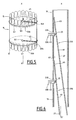
- the treatment device shown in Figures 1 to 5 comprises a tubular stent 11 X-axis X ', mounted coaxially on a single guard 13 and connected to the guard 13 by releasable retaining means.
- the stent 11 comprises a tubular stainless steel lattice that has spring properties. Thus, this stent is self-expanding.
- This endoprosthesis 11 is for example made by braiding a single wire of a superelastic material, as described in the patent application. European EP-A-0 857 471 .
- the lattice of the stent 11 defines, in the vicinity of a distal end 15 of the stent 11, a distal guide passageway 16A of the retaining means, and in the vicinity of a proximal end 17 of the stent 11, a 17A proximal guide passage retaining means.
- each guide passage 16A, 17A is delimited by a mesh of the lattice of the stent.
- the passages 16A, 17A are situated on the same longitudinal generatrix of the stent 11.
- the lattice has at the ends 15, 17 of the stent 11 folded son forming elbows.
- the stent 11 internally delimits a blood flow conduit 18 of axis X-X '.
- the passages 16A, 17A are delimited by rings integral with the lattice and arranged in the duct 18.
- the stent 11 is capable of deforming spontaneously from a retracted state, in which it has a small diameter (FIG. 1) in an expanded state, in which it has a larger diameter (FIG. dilated state constituting its state of rest.
- the guard 13 comprises a hollow flexible metal tube of axis X-X '.
- the inner diameter of the tube is adapted to thread it onto a thread-like surgical guide (not shown) installed on the patient, prior to the placement of the stent 11 in a blood circulation conduit of this patient.
- the guard 13 extends longitudinally in one piece between a distal end 19 intended to be implanted in the blood circulation duct and a proximal end 21 intended to be accessible to a surgeon.
- the proximal end 21 is located away from the stent 11.
- Distal and proximal retaining openings 23A and 23B are formed laterally in the guard 13, in the vicinity of the distal end 19 of the guard 13.
- the openings 23A and 23B are formed on the same side with respect to a median longitudinal plane of the guard 13.
- the distance separating the distal retaining aperture 23A from the proximal retaining aperture 23B is substantially equal to the length endoprosthesis 11 in its retracted state, taken in a longitudinal direction.
- the guard 13 defines at its proximal end 21 a control passage 25 selectively closed by means 27 for locking in position of the retaining means.
- the stent retaining means 11 comprise a distal retaining rod 31A and a proximal retaining rod 31B, respectively associated with a distal retaining wire 33A and a proximal retaining wire 33B.
- the distal retaining pin 31A and the proximal retaining pin 31B are of similar structures.
- the distal retaining wire 33A and the proximal retaining wire 33B are of similar structures. As a result, only distal retaining wire 33A and distal retaining pin 31A will be described below.
- the retaining rod 31A is disposed in the stent 13.
- the length of the rod 31A is greater than or equal to the distance between the distal retaining aperture 23A and the proximal end 21 of the stent 13.
- the rod 31A includes an end hook 35, an actuating portion 37, and a control portion 39 that protrudes through the control passage 25 at the proximal end 21 of the guard 13.
- the retaining rod 31A thus has a general shape of butt.
- the end hook 35 is located at the distal end of the actuating portion 37. It projects laterally with respect to the actuating portion 37 toward the distal retaining aperture 23A.
- the actuating portion 37 is made of a flexible metal rod. It extends into the guardian 13.
- the control section 39 extends the actuating portion 37 outside the guard 13, through the control passage 25.
- the rod 31A is movable in translation along the axis XX 'of the guard 13, between a distal position of release of the retaining wire 33A shown in FIG. 4, and a proximal position of traction of the retaining wire 33A represented on FIG. Figure 2
- the hook 35 extends substantially opposite the distal retaining aperture 23A.
- the control section 39 has a minimum length.
- the hook 35 In the proximal traction position, the hook 35 is located between the proximal retaining aperture 23B and the distal retaining aperture 23A. The length of the control section 39 is then maximum.
- the distal retaining wire 33A comprises a single strand of flexible material closed on itself.
- the distal retaining wire 33A thus forms a clamping loop 43, located outside the guard 13 to surround the stent 11, and a loop 45 engaged in the guard 13 through the distal retaining aperture 23A.
- the distal retaining wire 33A is permanently mounted on the stent 11.
- the tightening loop 43 surrounds the stent 11 outside the mesh, along a circumference about the X-X 'axis. It extends between a first end and a second end engaged in the proximal guide passage 16A and connected to the guide 45.
- the clamping loop 43 is engaged in the lattice of the stent 11, along a circumference, passing successively inside and outside the trellis.
- the guide 45 extends into the guard 13 by connecting the two ends of the clamping loop 43 through the retaining opening 23A.
- the loop 45 is engaged in the hook 35 of the retaining rod 31A.
- the clamping loop 43 is extensible between a holding configuration of the stent 11 in its retracted state, and a deployment configuration of the stent 11.
- the diameter of the clamping loop 43 is minimal, while the length of the loop 45 in the guard 13 is maximum.
- the stent 11 When the tightening loop 43 occupies its holding configuration of the stent 11, the stent 11 is held in its retracted state against the stent 13 along a peripheral side surface of the stent 13. Conversely, when the buckle 43 occupies its deployment configuration, the stent 11 is free to occupy its expanded state.
- the device is kept in a sterile package (not shown).
- each retaining rod 31 substantially occupies its release position of the loop 45, in which the hook 35 is located opposite a retaining opening 23A, 23B.
- the loop 45 remains engaged in an associated hook 35, so that the retaining rod 31A, 31B retains the retaining wire 33A, 33B.
- the distal and proximal retaining wires 33A and 33B are engaged around the lattice of the stent 11, so that each clamping loop 43 occupies its deployment configuration.
- the stent 11 is thus maintained in its expanded state.
- This packaging retains the mechanical properties of the stent 11, particularly the tubular lattice thereof is embedded in an extensible and waterproof film, such as an elastomer.
- a surgical guide (not shown) circulating in the blood circulation duct or vein from the external introduction point to the area of the vein or artery in which must be implanted the tubular stent 11.
- the surgeon extracts the device from its packaging for implantation of the stent 11 into the blood circulation conduit or the vein.
- the surgeon then releases the locking means 27 of the rods 31A, 31B and pulls on the control sections 39 of the retaining rods 31A, 31B, in order to increase the length of these sections 39.
- each hook 35 moves towards the proximal end 21 of the guard 13, until the retaining rods 31A, 31B occupy their position of retaining the loop.
- each retaining rod 31A, 31B pulls on a retaining wire 33A, 33B corresponding.
- the length of each loop 45 increases, and the diameter of the clamping loops 43 decreases correspondingly.
- the stent 11 thus passes from its expanded state to its retracted state against a peripheral lateral surface of the guard 13, in which the mesh is substantially in abutment against the guard 13, around this guard 13.
- the guard 13 is then located in the circulation duct 18.
- the stent 11 is thus introduced coaxially with the stent 13 to its place of implantation by displacement along the surgical guide (not shown).
- a sheath (not shown) is disposed around the stent 11, before this introduction, and removed once the introduction performed.
- the surgeon selectively releases the control portion 39 from the distal retaining pin 31A. Then, it gradually decreases the length of this section 39 by moving the rod 31A towards the distal end 19 of the guard 13, which moves the hook 35 towards the distal end 19.
- the length of the loop 45 decreases.
- the diameter of the clamping loop 43 increases correspondingly, which allows the deployment of the stent 11 radially relative to the axis XX 'of the stent 13 at the distal end 15 of the stent 11.
- the lattice therefore moves away from the guard 13 and approaches the walls P of the duct to be treated to bear against these walls P.
- the surgeon If the surgeon is not satisfied with the positioning of the distal end 15 of the stent 11 when it is deployed, it again actuates the control section 39 by moving the retaining rod 31A towards the proximal end 21 13. This increases the length of the loop 45 and decreases the active length of the clamping loop 43 to compress the stent 11 against the stent 13. The stent 11 is then moved to a more satisfactory position.
- the surgeon then deploys the proximal end 17 of the stent 11 by means of the proximal retaining wire 33B.
- the distal end 15 of the stent 11 is then irreversibly fixed to the walls P of the blood circulation conduit.
- the length of the retaining wires 31A, 31B is minimal, so that their circulation in the guard 13 has low risk of blockage.
- each loop 45 has an end ring 101, for example made of a radiopaque material, intended to be gripped by a hook 35.
- each retaining rod 31A, 31B is not located at the distal end of the rod 31A, 31B.
- each hook 35 defines on the rod 31A, 31B a proximal section 61 and a distal section 63 of non-zero length, adapted to retain the hook 35 in the guard 13.
- the hook 35 projects radially relative to the proximal section 61 and at the distal portion 63.
- the distal section 63 bears against the inner surface 67 of the guard 13 distal to opening 23A, 23B. This prevents the hook 35 from being driven by the passage 45 outside the guard 13 through the retaining opening 23A, 23B during the deployment of the stent 11. The reliability of the device is further improved.
- the two retaining rods 31A, 31B are mechanically connected at a point proximal to the retaining aperture proximal 23B when the hooks 35 are located opposite the retaining openings 23A, 23B.
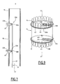
- the third device according to the invention shown in Figure 7, comprises a single retaining rod 31 provided with a distal retaining hook 35A located at the distal end of the shaft 31, and a proximal retaining hook 35B which protrudes with respect to the rod 31.
- the distance separating the distal hook 35A from the proximal hook 35B is substantially equal to the distance between the distal retaining aperture 23A and the proximal retaining aperture 23B.
- This third device allows the simultaneous deployment of the proximal end 17 and the distal end 15 of the stent 11.
- a fourth device according to the invention is shown in Figures 8 and 9.
- This device is a variant of the second processing device according to the invention.
- each retaining wire 33A, 33B is releasable from the endoprosthesis 11.
- each retaining wire 33A, 33B forms a main lead 45 connected to a first end of the clamping loop 43, and an auxiliary loop 201 disposed in the guard 13 and connected to a second end of the clamping loop 43 .
- the clamping loop 43 is formed by two adjacent strands of the retaining wire 33A, 33B. These two strands are folded in a loop at the first end of the clamping loop 43 to form the main loop 45 and are folded in a loop at the second end of the clamping loop 43 to form the auxiliary loop 201.
- the main passer 45 and the auxiliary passer 201 are connected to the clamping loop 43 through the same retainer aperture 23A, 23B and through the same guide passage 16A, 17A.
- each retaining rod 31A, 31B has at its distal end a retaining clip 203 of the auxiliary passer 201.
- the clip 203 is formed by a fold 205 of the distal portion 63 of the retaining pin 31A, 31B extending between the distal end of the rod 31A, 31B to a point proximal to the retention hook 35.
- the fold 205 extends opposite the hook 35 and the retaining opening 23A, 23B, with respect to the axis of the rod 31A, 31B.
- the clamp 203 opens towards the end proximal 21 of the guardian 13.
- the auxiliary passer 201 is engaged in the retaining clip 203.
- each retaining rod 31A, 31B When the surgeon extracts the fourth device from its package and moves each retaining rod 31A, 31B towards the proximal end 21 of the guard 13.
- the hook 35 and the clip 203 of each rod 31A, 31B also move toward this end. proximal end.
- the passer 45 and the auxiliary passer 201 are pulled in the guard 13 towards the proximal end 21 so that the length of the clamping loop 43 decreases to move the stent 11 from its expanded state to its retracted state against the guardian 13.
- the deployment of the stent 11 is similar to that of the second treatment device.
- the auxiliary loop 201 remains engaged in the clamp 203.
Landscapes
- Health & Medical Sciences (AREA)
- Cardiology (AREA)
- Engineering & Computer Science (AREA)
- Biomedical Technology (AREA)
- Heart & Thoracic Surgery (AREA)
- Transplantation (AREA)
- Oral & Maxillofacial Surgery (AREA)
- Vascular Medicine (AREA)
- Life Sciences & Earth Sciences (AREA)
- Animal Behavior & Ethology (AREA)
- General Health & Medical Sciences (AREA)
- Public Health (AREA)
- Veterinary Medicine (AREA)
- Media Introduction/Drainage Providing Device (AREA)
- Prostheses (AREA)
Applications Claiming Priority (1)
| Application Number | Priority Date | Filing Date | Title |
|---|---|---|---|
| FR0602932A FR2899096B1 (fr) | 2006-04-04 | 2006-04-04 | Dispositif de traitement d'un conduit de circulation du sang et procede de preparation de ce dispositif |
Publications (2)
| Publication Number | Publication Date |
|---|---|
| EP1842508A1 true EP1842508A1 (de) | 2007-10-10 |
| EP1842508B1 EP1842508B1 (de) | 2009-06-17 |
Family
ID=37022922
Family Applications (1)
| Application Number | Title | Priority Date | Filing Date |
|---|---|---|---|
| EP07290371A Ceased EP1842508B1 (de) | 2006-04-04 | 2007-03-28 | Vorrichtung zur Behandlung eines Blutschlauchs und Verfahren zur Herstellung dieser Vorrichtung |
Country Status (6)
| Country | Link |
|---|---|
| US (1) | US9427317B2 (de) |
| EP (1) | EP1842508B1 (de) |
| CN (1) | CN101049271B (de) |
| BR (1) | BRPI0701332B8 (de) |
| DE (1) | DE602007001291D1 (de) |
| FR (1) | FR2899096B1 (de) |
Cited By (9)
| Publication number | Priority date | Publication date | Assignee | Title |
|---|---|---|---|---|
| WO2009148607A1 (en) * | 2008-06-04 | 2009-12-10 | Gore Enterprise Holdings, Inc. | Controlled deployable medical device and method of making the same |
| WO2009148594A1 (en) * | 2008-06-04 | 2009-12-10 | Gore Enterprise Holdings, Inc. | Controlled deployable medical device and method of making the same |
| EP2133043A1 (de) * | 2008-06-11 | 2009-12-16 | Olympus Medical Systems Corporation | Stent-Einführungssystem und Stent-Einführungsverfahren |
| FR2947717A1 (fr) * | 2009-07-08 | 2011-01-14 | Cormove | Dispositif de traitement d'un conduit sanguin |
| WO2014179763A1 (en) * | 2013-05-03 | 2014-11-06 | Medtronic Inc. | Valve delivery tool |
| US9510962B2 (en) | 2006-06-16 | 2016-12-06 | Olympus Corporation | Stent delivery system |
| WO2017160756A1 (en) * | 2016-03-14 | 2017-09-21 | Medtronic Vascular Inc. | Transcatheter stented prosthetic heart valve delivery devices with primary and secondary release mechanisms |
| WO2017106161A3 (en) * | 2015-12-14 | 2017-12-14 | Medtronic Vascular Inc. | Devices and methods for transcatheter valve loading and implantation |
| WO2018136174A1 (en) * | 2017-01-20 | 2018-07-26 | Medtronic Vascular Inc. | Valve prosthesis having a radially-expandable sleeve integrated thereon for delivery and prevention of paravalvular leakage |
Families Citing this family (91)
| Publication number | Priority date | Publication date | Assignee | Title |
|---|---|---|---|---|
| DE102005007341B4 (de) * | 2005-02-17 | 2007-10-11 | Kasprzak, Piotr, Dr. | Stentprothese für die Gefäßchirurgie insbesondere im Bereich des Aortenbogens |
| FR2909857B1 (fr) | 2006-12-14 | 2009-03-06 | Perouse Soc Par Actions Simpli | Endovalve. |
| FR2913879B1 (fr) * | 2007-03-21 | 2009-06-12 | Perouse Soc Par Actions Simpli | Dispositif de largage d'un implant expansible radialement, necessaire de traitement et procede de largage associe |
| US9226813B2 (en) | 2007-12-26 | 2016-01-05 | Cook Medical Technologies Llc | Low profile non-symmetrical stent |
| GB2475494B (en) | 2009-11-18 | 2011-11-23 | Cook William Europ | Stent graft and introducer assembly |
| GB2476451A (en) | 2009-11-19 | 2011-06-29 | Cook William Europ | Stent Graft |
| US8574284B2 (en) | 2007-12-26 | 2013-11-05 | Cook Medical Technologies Llc | Low profile non-symmetrical bare alignment stents with graft |
| US9180030B2 (en) | 2007-12-26 | 2015-11-10 | Cook Medical Technologies Llc | Low profile non-symmetrical stent |
| DE102008012113A1 (de) * | 2008-03-02 | 2009-09-03 | Transcatheter Technologies Gmbh | Stent, welcher vom expandierten Zustand erneut im Durchmesser kontrolliert verringerbar ist |
| US9387312B2 (en) | 2008-09-15 | 2016-07-12 | Brightwater Medical, Inc. | Convertible nephroureteral catheter |
| GB2464977B (en) | 2008-10-31 | 2010-11-03 | William Cook Europe As | Introducer for deploying a stent graft in a curved lumen and stent graft therefor |
| US11376114B2 (en) | 2008-10-31 | 2022-07-05 | Cook Medical Technologies Llc | Introducer for deploying a stent graft in a curved lumen and stent graft therefor |
| US9956100B2 (en) | 2009-09-15 | 2018-05-01 | Brightwater Medical, Inc. | Systems and methods for coupling and decoupling a catheter |
| US9757263B2 (en) | 2009-11-18 | 2017-09-12 | Cook Medical Technologies Llc | Stent graft and introducer assembly |
| DE102010008338A1 (de) * | 2010-02-17 | 2011-08-18 | Transcatheter Technologies GmbH, 93053 | Einrichtung, vorgesehen, um an einem Katheter befestigt oder mit diesem verbunden zu werden, Katheter und Verfahren |
| US8623075B2 (en) * | 2010-04-21 | 2014-01-07 | Medtronic, Inc. | Transcatheter prosthetic heart valve delivery system and method with controlled expansion of prosthetic heart valve |
| US8579964B2 (en) | 2010-05-05 | 2013-11-12 | Neovasc Inc. | Transcatheter mitral valve prosthesis |
| US9101455B2 (en) * | 2010-08-13 | 2015-08-11 | Cook Medical Technologies Llc | Preloaded wire for endoluminal device |
| CA2747610C (en) | 2010-08-13 | 2014-09-16 | Cook Medical Technologies Llc | Precannulated fenestration |
| DE102010037529A1 (de) * | 2010-09-14 | 2012-03-15 | Transcatheter Technologies Gmbh | Einrichtung, vorgesehen, um an einem Katheter befestigt oder mit diesem verbunden zu werden, Katheter und Verfahren |
| DE102010061371A1 (de) * | 2010-12-20 | 2012-06-21 | Transcatheter Technologies Gmbh | Vorrichtung mit individuellen Schaftfasern und Set zum Falten oder Entfalten eines medizinischen Implantats und Verfahren |
| GB201106017D0 (en) * | 2011-04-08 | 2011-05-25 | Lombard Medical Plc | Apparatus for deploying a stent graft |
| US9308087B2 (en) | 2011-04-28 | 2016-04-12 | Neovasc Tiara Inc. | Sequentially deployed transcatheter mitral valve prosthesis |
| US9554897B2 (en) | 2011-04-28 | 2017-01-31 | Neovasc Tiara Inc. | Methods and apparatus for engaging a valve prosthesis with tissue |
| EP2529705B1 (de) * | 2011-06-03 | 2019-02-06 | Cook Medical Technologies LLC | Einführer zum Einsetzen eines Implantats |
| US9278018B2 (en) * | 2011-12-14 | 2016-03-08 | Cook Medical Technologies Llc | Circumferential trigger wire for deploying an endoluminal prosthesis |
| US8882828B2 (en) * | 2012-04-27 | 2014-11-11 | Medtronic Vascular, Inc. | Ring on a closed web stent-graft for use in tip capture |
| US9345573B2 (en) | 2012-05-30 | 2016-05-24 | Neovasc Tiara Inc. | Methods and apparatus for loading a prosthesis onto a delivery system |
| RU2521835C2 (ru) * | 2012-10-18 | 2014-07-10 | Заза Александрович Кавтеладзе | Устройство для установки стента с покрытием в сонную артерию |
| CN103815939B (zh) * | 2012-11-19 | 2017-06-27 | 微创心脉医疗科技(上海)有限公司 | 覆膜支架收紧装置及收紧方法 |
| US9622893B2 (en) * | 2012-12-20 | 2017-04-18 | Cook Medical Technologies Llc | Apparatus and method for improved deployment of endovascular grafts |
| US11439525B2 (en) | 2012-12-27 | 2022-09-13 | Venus Medtech (Hangzhou) Inc. | Implant delivery device adapted to be attached to or interconnected with a catheter, catheter and method |
| EP2938291B2 (de) * | 2012-12-27 | 2023-01-11 | Venus MedTech (HangZhou), Inc. | Vorrichtung und set zum zusammenklappen oder aufklappen eines medizinischen implantats mit einem klemmmechanismus |
| US10561509B2 (en) | 2013-03-13 | 2020-02-18 | DePuy Synthes Products, Inc. | Braided stent with expansion ring and method of delivery |
| US9572665B2 (en) | 2013-04-04 | 2017-02-21 | Neovasc Tiara Inc. | Methods and apparatus for delivering a prosthetic valve to a beating heart |
| CN103690202B (zh) * | 2013-12-30 | 2016-04-20 | 先健科技(深圳)有限公司 | 植入体的输送装置与植入医疗器械 |
| EP3936088A1 (de) | 2014-08-12 | 2022-01-12 | Merit Medical Systems, Inc. | Systeme und verfahren zur kopplung und entkopplung eines katheters |
| US10206796B2 (en) | 2014-08-27 | 2019-02-19 | DePuy Synthes Products, Inc. | Multi-strand implant with enhanced radiopacity |
| CN107405206A (zh) * | 2015-01-14 | 2017-11-28 | 库克医学技术有限责任公司 | 缝合线‑金属丝支架部署系统 |
| DE202016008737U1 (de) | 2015-12-15 | 2019-04-05 | Neovasc Tiara Inc. | Transseptales Zuführsystem |
| CN108882981B (zh) | 2016-01-29 | 2021-08-10 | 内奥瓦斯克迪亚拉公司 | 用于防止流出阻塞的假体瓣膜 |
| US10076428B2 (en) | 2016-08-25 | 2018-09-18 | DePuy Synthes Products, Inc. | Expansion ring for a braided stent |
| US10292851B2 (en) | 2016-09-30 | 2019-05-21 | DePuy Synthes Products, Inc. | Self-expanding device delivery apparatus with dual function bump |
| CN106473835B (zh) * | 2016-10-11 | 2019-04-19 | 有研医疗器械(北京)有限公司 | 分支型覆膜支架及其输送系统和释放方法 |
| US10182927B2 (en) * | 2016-10-21 | 2019-01-22 | DePuy Synthes Products, Inc. | Expansion ring for a braided stent |
| CN109996581B (zh) | 2016-11-21 | 2021-10-15 | 内奥瓦斯克迪亚拉公司 | 用于快速收回经导管心脏瓣膜递送系统的方法和系统 |
| US10653523B2 (en) | 2017-01-19 | 2020-05-19 | 4C Medical Technologies, Inc. | Systems, methods and devices for delivery systems, methods and devices for implanting prosthetic heart valves |
| US10561495B2 (en) | 2017-01-24 | 2020-02-18 | 4C Medical Technologies, Inc. | Systems, methods and devices for two-step delivery and implantation of prosthetic heart valve |
| WO2018156851A1 (en) | 2017-02-24 | 2018-08-30 | Bolton Medical, Inc. | Vascular prosthesis with moveable fenestration |
| EP3534837A1 (de) | 2017-02-24 | 2019-09-11 | Bolton Medical, Inc. | Begrenzbares stentgraft, einführungssystem und verfahren zur verwendung |
| WO2018156854A1 (en) | 2017-02-24 | 2018-08-30 | Bolton Medical, Inc. | Radially adjustable stent graft delivery system |
| WO2018156842A1 (en) | 2017-02-24 | 2018-08-30 | Bolton Medical, Inc. | System and method to radially constrict a stent graft |
| JP7112393B2 (ja) | 2017-02-24 | 2022-08-03 | ボルトン メディカル インコーポレイテッド | シースが収縮されたステントグラフト送達システムおよび使用方法 |
| CN109843226B (zh) | 2017-02-24 | 2022-05-17 | 波顿医疗公司 | 用于径向收缩支架移植物的递送系统和使用方法 |
| WO2018156848A1 (en) | 2017-02-24 | 2018-08-30 | Bolton Medical, Inc. | Vascular prosthesis with crimped adapter and methods of use |
| US10561497B2 (en) * | 2017-03-07 | 2020-02-18 | Medtronic Vascular, Inc. | Delivery system having a short capsule segment and a cinch mechanism and methods of use thereof |
| US12029647B2 (en) | 2017-03-07 | 2024-07-09 | 4C Medical Technologies, Inc. | Systems, methods and devices for prosthetic heart valve with single valve leaflet |
| WO2018165559A1 (en) * | 2017-03-09 | 2018-09-13 | Medtronic Vascular Inc. | Tension management devices for stented prosthesis delivery device |
| EP3600157A1 (de) | 2017-03-28 | 2020-02-05 | Medtronic Inc. | Umlenkdesign für zugelement zur erzielung der kompression einer transkatheter-stentprothese |
| US10709541B2 (en) | 2017-04-28 | 2020-07-14 | Cook Medical Technologies Llc | Systems and methods for adjusting the diameter of an endoluminal prosthesis and an endoluminal prosthesis configured for the same |
| US12036113B2 (en) | 2017-06-14 | 2024-07-16 | 4C Medical Technologies, Inc. | Delivery of heart chamber prosthetic valve implant |
| CA3073834A1 (en) | 2017-08-25 | 2019-02-28 | Neovasc Tiara Inc. | Sequentially deployed transcatheter mitral valve prosthesis |
| CN110121319B (zh) * | 2017-10-31 | 2023-05-09 | 波顿医疗公司 | 远侧转矩部件、递送系统及其使用方法 |
| EP3801383A4 (de) | 2018-05-31 | 2022-03-16 | Endologix LLC | Stenttransplantatsysteme mit rückhaltemitteln in kanälen und verfahren dafür |
| EP3813739B1 (de) * | 2018-06-29 | 2026-03-11 | Avantec Vascular Corporation | Systeme und verfahren für implantate und freisetzungsvorrichtungen |
| AU2019204522A1 (en) | 2018-07-30 | 2020-02-13 | DePuy Synthes Products, Inc. | Systems and methods of manufacturing and using an expansion ring |
| US10456280B1 (en) | 2018-08-06 | 2019-10-29 | DePuy Synthes Products, Inc. | Systems and methods of using a braided implant |
| US10278848B1 (en) | 2018-08-06 | 2019-05-07 | DePuy Synthes Products, Inc. | Stent delivery with expansion assisting delivery wire |
| US11857441B2 (en) | 2018-09-04 | 2024-01-02 | 4C Medical Technologies, Inc. | Stent loading device |
| US11000000B2 (en) * | 2018-09-14 | 2021-05-11 | 4C Medical Technologies, Inc. | Repositioning wires and methods for repositioning prosthetic heart valve devices within a heart chamber and related systems, devices and methods |
| WO2020093172A1 (en) | 2018-11-08 | 2020-05-14 | Neovasc Tiara Inc. | Ventricular deployment of a transcatheter mitral valve prosthesis |
| US11039944B2 (en) | 2018-12-27 | 2021-06-22 | DePuy Synthes Products, Inc. | Braided stent system with one or more expansion rings |
| US12544226B2 (en) | 2019-02-14 | 2026-02-10 | 4C Medical Technologies, Inc. | Hydrophilic skirt for paravalvular leak mitigation and fit and apposition optimization for prosthetic heart valve implants |
| WO2020185597A1 (en) | 2019-03-08 | 2020-09-17 | Neovasc Tiara Inc. | Retrievable prosthesis delivery system |
| US11602429B2 (en) | 2019-04-01 | 2023-03-14 | Neovasc Tiara Inc. | Controllably deployable prosthetic valve |
| EP3952792A4 (de) | 2019-04-10 | 2023-01-04 | Neovasc Tiara Inc. | Herzklappenprothese mit natürlichem blutfluss |
| US11452628B2 (en) | 2019-04-15 | 2022-09-27 | 4C Medical Technologies, Inc. | Loading systems for collapsible prosthetic heart valve devices and methods thereof |
| EP3972673B1 (de) | 2019-05-20 | 2026-01-28 | Neovasc Tiara Inc. | Einführungsvorrichtung mit hämostasemechanismus |
| CN114144144B (zh) | 2019-06-20 | 2026-01-13 | 内奥瓦斯克迪亚拉公司 | 低轮廓假体二尖瓣 |
| CN112891018B (zh) * | 2019-12-03 | 2023-06-02 | 先健科技(深圳)有限公司 | 管腔支架 |
| US12133797B2 (en) | 2020-01-31 | 2024-11-05 | 4C Medical Technologies, Inc. | Prosthetic heart valve delivery system: paddle attachment feature |
| US11931253B2 (en) | 2020-01-31 | 2024-03-19 | 4C Medical Technologies, Inc. | Prosthetic heart valve delivery system: ball-slide attachment |
| WO2021168031A1 (en) * | 2020-02-18 | 2021-08-26 | Edwards Lifesciences Corporation | Apparatus for monitoring valve expansion |
| US12053375B2 (en) | 2020-03-05 | 2024-08-06 | 4C Medical Technologies, Inc. | Prosthetic mitral valve with improved atrial and/or annular apposition and paravalvular leakage mitigation |
| US11992403B2 (en) | 2020-03-06 | 2024-05-28 | 4C Medical Technologies, Inc. | Devices, systems and methods for improving recapture of prosthetic heart valve device with stent frame having valve support with inwardly stent cells |
| US12226327B2 (en) | 2020-04-15 | 2025-02-18 | Merit Medical Systems, Inc. | Systems and methods for coupling and decoupling a catheter |
| US12491097B2 (en) | 2020-06-05 | 2025-12-09 | Merit Medical Systems, Inc. | Systems and methods for coupling and decoupling a catheter |
| GB2605559B (en) | 2021-01-07 | 2023-04-05 | Cook Medical Technologies Llc | Stent graft |
| US12588998B1 (en) | 2022-09-01 | 2026-03-31 | 4C Medical Technologies, Inc. | Prosthetic heart valve for natural blood flow |
| US20240366366A1 (en) | 2023-03-24 | 2024-11-07 | 4C Medical Technologies, Inc. | Implant delivery |
| GB2631689B (en) * | 2023-07-05 | 2026-04-29 | Cook Medical Technologies Llc | Medical Device System |
Citations (6)
| Publication number | Priority date | Publication date | Assignee | Title |
|---|---|---|---|---|
| US5713948A (en) * | 1995-07-19 | 1998-02-03 | Uflacker; Renan | Adjustable and retrievable graft and graft delivery system for stent-graft system |
| EP0829242A1 (de) * | 1996-08-19 | 1998-03-18 | Schneider (Europe) Ag | Vorrichtung zum Entfernen einer implantierten Endoprothese |
| US5800506A (en) * | 1994-04-26 | 1998-09-01 | Laboratoire Perouse Implant | Device for treating a blood vessel |
| US20050119722A1 (en) * | 2003-09-12 | 2005-06-02 | Mikolaj Styrc | Device for treating a blood vessel and a method of preparing the device |
| FR2865926A1 (fr) * | 2004-02-11 | 2005-08-12 | Perouse Laboratoires | Prothese tubulaire. |
| FR2874812A1 (fr) * | 2004-09-07 | 2006-03-10 | Perouse Soc Par Actions Simpli | Valve protheique interchangeable |
Family Cites Families (6)
| Publication number | Priority date | Publication date | Assignee | Title |
|---|---|---|---|---|
| IT1269443B (it) * | 1994-01-19 | 1997-04-01 | Stefano Nazari | Protesi vascolare per la sostituzione o il rivestimento interno di vasi sanguigni di medio e grande diametro e dispositivo per la sua applicazione senza interruzione del flusso ematico |
| US6248100B1 (en) * | 1997-08-14 | 2001-06-19 | Scimed Life Systems, Inc. | Drainage catheter delivery system |
| US20030050684A1 (en) * | 2001-09-10 | 2003-03-13 | Abrams Robert M. | Internal restraint for delivery of self-expanding stents |
| US6821291B2 (en) * | 2001-06-01 | 2004-11-23 | Ams Research Corporation | Retrievable stent and method of use thereof |
| AU2004277968B2 (en) * | 2003-09-30 | 2008-10-09 | Merit Medical Systems, Inc. | Removable stent |
| DE602005027608D1 (de) * | 2004-10-25 | 2011-06-01 | Merit Medical Systems Inc | Vorrichtung zum entfernen und versetzen eines stents |
-
2006
- 2006-04-04 FR FR0602932A patent/FR2899096B1/fr not_active Expired - Fee Related
-
2007
- 2007-03-28 DE DE602007001291T patent/DE602007001291D1/de active Active
- 2007-03-28 EP EP07290371A patent/EP1842508B1/de not_active Ceased
- 2007-03-29 BR BRPI0701332A patent/BRPI0701332B8/pt not_active IP Right Cessation
- 2007-04-03 CN CN2007100906961A patent/CN101049271B/zh not_active Expired - Fee Related
- 2007-04-03 US US11/730,699 patent/US9427317B2/en active Active
Patent Citations (6)
| Publication number | Priority date | Publication date | Assignee | Title |
|---|---|---|---|---|
| US5800506A (en) * | 1994-04-26 | 1998-09-01 | Laboratoire Perouse Implant | Device for treating a blood vessel |
| US5713948A (en) * | 1995-07-19 | 1998-02-03 | Uflacker; Renan | Adjustable and retrievable graft and graft delivery system for stent-graft system |
| EP0829242A1 (de) * | 1996-08-19 | 1998-03-18 | Schneider (Europe) Ag | Vorrichtung zum Entfernen einer implantierten Endoprothese |
| US20050119722A1 (en) * | 2003-09-12 | 2005-06-02 | Mikolaj Styrc | Device for treating a blood vessel and a method of preparing the device |
| FR2865926A1 (fr) * | 2004-02-11 | 2005-08-12 | Perouse Laboratoires | Prothese tubulaire. |
| FR2874812A1 (fr) * | 2004-09-07 | 2006-03-10 | Perouse Soc Par Actions Simpli | Valve protheique interchangeable |
Cited By (25)
| Publication number | Priority date | Publication date | Assignee | Title |
|---|---|---|---|---|
| US9510962B2 (en) | 2006-06-16 | 2016-12-06 | Olympus Corporation | Stent delivery system |
| US9907683B2 (en) | 2008-06-04 | 2018-03-06 | W. L. Gore & Associates, Inc. | Controlled deployable medical device and method of making the same |
| WO2009148594A1 (en) * | 2008-06-04 | 2009-12-10 | Gore Enterprise Holdings, Inc. | Controlled deployable medical device and method of making the same |
| EP2282705A1 (de) * | 2008-06-04 | 2011-02-16 | Gore Enterprise Holdings, Inc. | Gesteuerte einsetzbare medizinische vorrichtung und verfahren zu ihrer herstellung |
| WO2009148607A1 (en) * | 2008-06-04 | 2009-12-10 | Gore Enterprise Holdings, Inc. | Controlled deployable medical device and method of making the same |
| US10219925B2 (en) | 2008-06-04 | 2019-03-05 | W. L. Gore & Associates, Inc. | Controlled deployable medical device and method of making the same |
| EP2133043A1 (de) * | 2008-06-11 | 2009-12-16 | Olympus Medical Systems Corporation | Stent-Einführungssystem und Stent-Einführungsverfahren |
| US8034094B2 (en) | 2008-06-11 | 2011-10-11 | Olympus Medical Systems Corp. | Stent delivery system and stent delivery method |
| FR2947717A1 (fr) * | 2009-07-08 | 2011-01-14 | Cormove | Dispositif de traitement d'un conduit sanguin |
| US10568739B2 (en) | 2013-05-03 | 2020-02-25 | Medtronic, Inc. | Valve delivery tool |
| US9629718B2 (en) | 2013-05-03 | 2017-04-25 | Medtronic, Inc. | Valve delivery tool |
| US11793637B2 (en) | 2013-05-03 | 2023-10-24 | Medtronic, Inc. | Valve delivery tool |
| WO2014179763A1 (en) * | 2013-05-03 | 2014-11-06 | Medtronic Inc. | Valve delivery tool |
| US10779942B2 (en) | 2015-12-14 | 2020-09-22 | Medtronic Vascular, Inc. | Devices and methods for transcatheter valve loading and implantation |
| AU2016370464B2 (en) * | 2015-12-14 | 2019-07-18 | Medtronic Vascular Inc. | Devices and methods for transcatheter valve loading and implantation |
| US10441420B2 (en) | 2015-12-14 | 2019-10-15 | Medtronic Vascular, Inc. | Devices and methods for transcatheter valve loading and implantation |
| WO2017106161A3 (en) * | 2015-12-14 | 2017-12-14 | Medtronic Vascular Inc. | Devices and methods for transcatheter valve loading and implantation |
| US11395737B2 (en) | 2015-12-14 | 2022-07-26 | Medtronic Vascular, Inc. | Devices and methods for transcatheter valve loading and implantation |
| US11617651B2 (en) | 2015-12-14 | 2023-04-04 | Medtronic Vascular, Inc. | Devices and methods for transcatheter valve loading and implantation |
| US10420642B2 (en) | 2016-03-14 | 2019-09-24 | Medtronic Vascular, Inc. | Transcatheter stented prosthetic heart valve delivery devices |
| WO2017160756A1 (en) * | 2016-03-14 | 2017-09-21 | Medtronic Vascular Inc. | Transcatheter stented prosthetic heart valve delivery devices with primary and secondary release mechanisms |
| US10433993B2 (en) | 2017-01-20 | 2019-10-08 | Medtronic Vascular, Inc. | Valve prosthesis having a radially-expandable sleeve integrated thereon for delivery and prevention of paravalvular leakage |
| WO2018136174A1 (en) * | 2017-01-20 | 2018-07-26 | Medtronic Vascular Inc. | Valve prosthesis having a radially-expandable sleeve integrated thereon for delivery and prevention of paravalvular leakage |
| US11666443B2 (en) | 2017-01-20 | 2023-06-06 | Medtronic Vascular, Inc. | Valve prosthesis having a radially expandable sleeve integrated thereon for delivery and prevention of paravalvular leakage |
| US12239535B2 (en) | 2017-01-20 | 2025-03-04 | Medtronic Vascular, Inc. | Valve prosthesis having a radially expandable sleeve integrated thereon for delivery and prevention of paravalvular leakage |
Also Published As
| Publication number | Publication date |
|---|---|
| FR2899096B1 (fr) | 2008-12-05 |
| CN101049271A (zh) | 2007-10-10 |
| CN101049271B (zh) | 2011-10-19 |
| BRPI0701332A (pt) | 2007-12-11 |
| US9427317B2 (en) | 2016-08-30 |
| BRPI0701332B8 (pt) | 2021-06-22 |
| DE602007001291D1 (de) | 2009-07-30 |
| FR2899096A1 (fr) | 2007-10-05 |
| BRPI0701332B1 (pt) | 2018-08-07 |
| US20070233223A1 (en) | 2007-10-04 |
| EP1842508B1 (de) | 2009-06-17 |
Similar Documents
| Publication | Publication Date | Title |
|---|---|---|
| EP1842508B1 (de) | Vorrichtung zur Behandlung eines Blutschlauchs und Verfahren zur Herstellung dieser Vorrichtung | |
| EP1976454B1 (de) | Vorrichtung zur behandlung einer blutführenden leitung und zugehöriges herstellungsverfahren | |
| EP1713414B1 (de) | Röhrenförmige prothese | |
| FR2894131A1 (fr) | Dispositif de traitement d'un vaisseau sanguin, et necessaire de traitement associe. | |
| FR2863160A1 (fr) | Dispositif de traitement d'un vaisseau sanguin et procede de preparation de ce dispositif | |
| FR2913879A1 (fr) | Dispositif de largage d'un implant expansible radialement, necessaire de traitement et procede de largage associe | |
| EP1898847B1 (de) | Satz zum einführen eines hohlraumbehandlungselements | |
| WO2010001012A1 (fr) | Dispositif de traitement d'un conduit de circulation du sang | |
| EP1909695B1 (de) | Vorrichtung zur behandlung eines blutgefässes | |
| EP0925029B1 (de) | Vorrichtung zur insbesondere endoskopischen entfernung von blutgefässen | |
| EP2266503B1 (de) | Verfahren zur herstellung für eine herzklappenprothese | |
| EP2000116B1 (de) | Kit zum Implantieren in eine Blutkreislaufbahn | |
| EP2005918B1 (de) | Röhrenförmige Prothese und entsprechendes Zubehör | |
| EP0679374A1 (de) | Endoprothese zur Behandlung von Blutgefässen | |
| FR3023703A1 (fr) | Dispositif de traitement d'un conduit de circulation du sang | |
| WO2009044082A2 (fr) | Dispositif de traitement d'un conduit de circulation du sang | |
| FR2932979A1 (fr) | Dispositif introducteur s'etendant entre un point proximal et un point distal et necessaire de traitement associe. | |
| FR2946865A1 (fr) | Dispositif de traitement d'un conduit de circulation du sang | |
| EP3644909B1 (de) | Griff zur freisetzung eines stents und vorrichtung mit dem griff | |
| FR3108029A1 (fr) | Dispositif de traitement d’un vaisseau sanguin | |
| FR2779938A1 (fr) | Necessaire de traitement d'un vaisseau sanguin | |
| FR2947717A1 (fr) | Dispositif de traitement d'un conduit sanguin | |
| FR2727617A1 (fr) | Dispositif d'eveinage pour realiser l'ablation d'une veine par invagination | |
| WO2021064303A1 (fr) | Dispositif de pose et de fixation d'un implant de renfort sur une valve mitrale d'un cœur, avec des sutures a memoire de forme et par voie transfemorale | |
| FR2945439A1 (fr) | Necessaire de traitement d'un conduit de circulation du sang comprenant un introducteur |
Legal Events
| Date | Code | Title | Description |
|---|---|---|---|
| PUAI | Public reference made under article 153(3) epc to a published international application that has entered the european phase |
Free format text: ORIGINAL CODE: 0009012 |
|
| AK | Designated contracting states |
Kind code of ref document: A1 Designated state(s): AT BE BG CH CY CZ DE DK EE ES FI FR GB GR HU IE IS IT LI LT LU LV MC MT NL PL PT RO SE SI SK TR |
|
| AX | Request for extension of the european patent |
Extension state: AL BA HR MK YU |
|
| 17P | Request for examination filed |
Effective date: 20071006 |
|
| 17Q | First examination report despatched |
Effective date: 20071126 |
|
| AKX | Designation fees paid |
Designated state(s): DE GB IT |
|
| GRAP | Despatch of communication of intention to grant a patent |
Free format text: ORIGINAL CODE: EPIDOSNIGR1 |
|
| GRAS | Grant fee paid |
Free format text: ORIGINAL CODE: EPIDOSNIGR3 |
|
| GRAA | (expected) grant |
Free format text: ORIGINAL CODE: 0009210 |
|
| AK | Designated contracting states |
Kind code of ref document: B1 Designated state(s): DE GB IT |
|
| REG | Reference to a national code |
Ref country code: GB Ref legal event code: FG4D Free format text: NOT ENGLISH |
|
| REF | Corresponds to: |
Ref document number: 602007001291 Country of ref document: DE Date of ref document: 20090730 Kind code of ref document: P |
|
| PLBE | No opposition filed within time limit |
Free format text: ORIGINAL CODE: 0009261 |
|
| STAA | Information on the status of an ep patent application or granted ep patent |
Free format text: STATUS: NO OPPOSITION FILED WITHIN TIME LIMIT |
|
| 26N | No opposition filed |
Effective date: 20100318 |
|
| PG25 | Lapsed in a contracting state [announced via postgrant information from national office to epo] |
Ref country code: IT Free format text: LAPSE BECAUSE OF NON-PAYMENT OF DUE FEES Effective date: 20100328 |
|
| REG | Reference to a national code |
Ref country code: GB Ref legal event code: 732E Free format text: REGISTERED BETWEEN 20151029 AND 20151104 |
|
| REG | Reference to a national code |
Ref country code: DE Ref legal event code: R082 Ref document number: 602007001291 Country of ref document: DE Representative=s name: VIERING, JENTSCHURA & PARTNER MBB PATENT- UND , DE Ref country code: DE Ref legal event code: R081 Ref document number: 602007001291 Country of ref document: DE Owner name: CORMOVE, FR Free format text: FORMER OWNER: LABORATOIRES PEROUSE, IVRY LE TEMPLE, FR |
|
| PGFP | Annual fee paid to national office [announced via postgrant information from national office to epo] |
Ref country code: GB Payment date: 20220225 Year of fee payment: 16 Ref country code: DE Payment date: 20220217 Year of fee payment: 16 |
|
| PGFP | Annual fee paid to national office [announced via postgrant information from national office to epo] |
Ref country code: IT Payment date: 20220217 Year of fee payment: 16 |
|
| REG | Reference to a national code |
Ref country code: DE Ref legal event code: R119 Ref document number: 602007001291 Country of ref document: DE |
|
| GBPC | Gb: european patent ceased through non-payment of renewal fee |
Effective date: 20230328 |
|
| PG25 | Lapsed in a contracting state [announced via postgrant information from national office to epo] |
Ref country code: GB Free format text: LAPSE BECAUSE OF NON-PAYMENT OF DUE FEES Effective date: 20230328 |
|
| PG25 | Lapsed in a contracting state [announced via postgrant information from national office to epo] |
Ref country code: GB Free format text: LAPSE BECAUSE OF NON-PAYMENT OF DUE FEES Effective date: 20230328 Ref country code: DE Free format text: LAPSE BECAUSE OF NON-PAYMENT OF DUE FEES Effective date: 20231003 |
|
| PG25 | Lapsed in a contracting state [announced via postgrant information from national office to epo] |
Ref country code: IT Free format text: LAPSE BECAUSE OF NON-PAYMENT OF DUE FEES Effective date: 20230328 |