EP1842580A2 - Dispositif destiné au dessalage électrochimique continu avec une étape membranaire intégrée - Google Patents
Dispositif destiné au dessalage électrochimique continu avec une étape membranaire intégrée Download PDFInfo
- Publication number
- EP1842580A2 EP1842580A2 EP07007050A EP07007050A EP1842580A2 EP 1842580 A2 EP1842580 A2 EP 1842580A2 EP 07007050 A EP07007050 A EP 07007050A EP 07007050 A EP07007050 A EP 07007050A EP 1842580 A2 EP1842580 A2 EP 1842580A2
- Authority
- EP
- European Patent Office
- Prior art keywords
- module
- ultrafiltration
- electrodeionization
- diluate
- modules
- Prior art date
- Legal status (The legal status is an assumption and is not a legal conclusion. Google has not performed a legal analysis and makes no representation as to the accuracy of the status listed.)
- Granted
Links
Images


Classifications
-
- B—PERFORMING OPERATIONS; TRANSPORTING
- B01—PHYSICAL OR CHEMICAL PROCESSES OR APPARATUS IN GENERAL
- B01D—SEPARATION
- B01D61/00—Processes of separation using semi-permeable membranes, e.g. dialysis, osmosis or ultrafiltration; Apparatus, accessories or auxiliary operations specially adapted therefor
- B01D61/58—Multistep processes
-
- B—PERFORMING OPERATIONS; TRANSPORTING
- B01—PHYSICAL OR CHEMICAL PROCESSES OR APPARATUS IN GENERAL
- B01D—SEPARATION
- B01D61/00—Processes of separation using semi-permeable membranes, e.g. dialysis, osmosis or ultrafiltration; Apparatus, accessories or auxiliary operations specially adapted therefor
- B01D61/42—Electrodialysis; Electro-osmosis ; Electro-ultrafiltration; Membrane capacitive deionization
- B01D61/44—Ion-selective electrodialysis
- B01D61/46—Apparatus therefor
- B01D61/48—Apparatus therefor having one or more compartments filled with ion-exchange material, e.g. electrodeionisation
-
- B—PERFORMING OPERATIONS; TRANSPORTING
- B01—PHYSICAL OR CHEMICAL PROCESSES OR APPARATUS IN GENERAL
- B01D—SEPARATION
- B01D63/00—Apparatus in general for separation processes using semi-permeable membranes
- B01D63/02—Hollow fibre modules
- B01D63/024—Hollow fibre modules with a single potted end
- B01D63/0241—Hollow fibre modules with a single potted end being U-shaped
-
- B—PERFORMING OPERATIONS; TRANSPORTING
- B01—PHYSICAL OR CHEMICAL PROCESSES OR APPARATUS IN GENERAL
- B01D—SEPARATION
- B01D63/00—Apparatus in general for separation processes using semi-permeable membranes
- B01D63/10—Spiral-wound membrane modules
-
- B—PERFORMING OPERATIONS; TRANSPORTING
- B01—PHYSICAL OR CHEMICAL PROCESSES OR APPARATUS IN GENERAL
- B01D—SEPARATION
- B01D2313/00—Details relating to membrane modules or apparatus
- B01D2313/08—Flow guidance means within the module or the apparatus
-
- B—PERFORMING OPERATIONS; TRANSPORTING
- B01—PHYSICAL OR CHEMICAL PROCESSES OR APPARATUS IN GENERAL
- B01D—SEPARATION
- B01D2313/00—Details relating to membrane modules or apparatus
- B01D2313/24—Specific pressurizing or depressurizing means
-
- B—PERFORMING OPERATIONS; TRANSPORTING
- B01—PHYSICAL OR CHEMICAL PROCESSES OR APPARATUS IN GENERAL
- B01D—SEPARATION
- B01D61/00—Processes of separation using semi-permeable membranes, e.g. dialysis, osmosis or ultrafiltration; Apparatus, accessories or auxiliary operations specially adapted therefor
- B01D61/02—Reverse osmosis; Hyperfiltration ; Nanofiltration
- B01D61/025—Reverse osmosis; Hyperfiltration
-
- B—PERFORMING OPERATIONS; TRANSPORTING
- B01—PHYSICAL OR CHEMICAL PROCESSES OR APPARATUS IN GENERAL
- B01D—SEPARATION
- B01D61/00—Processes of separation using semi-permeable membranes, e.g. dialysis, osmosis or ultrafiltration; Apparatus, accessories or auxiliary operations specially adapted therefor
- B01D61/14—Ultrafiltration; Microfiltration
- B01D61/145—Ultrafiltration
-
- C—CHEMISTRY; METALLURGY
- C02—TREATMENT OF WATER, WASTE WATER, SEWAGE, OR SLUDGE
- C02F—TREATMENT OF WATER, WASTE WATER, SEWAGE, OR SLUDGE
- C02F2103/00—Nature of the water, waste water, sewage or sludge to be treated
- C02F2103/08—Seawater, e.g. for desalination
-
- Y—GENERAL TAGGING OF NEW TECHNOLOGICAL DEVELOPMENTS; GENERAL TAGGING OF CROSS-SECTIONAL TECHNOLOGIES SPANNING OVER SEVERAL SECTIONS OF THE IPC; TECHNICAL SUBJECTS COVERED BY FORMER USPC CROSS-REFERENCE ART COLLECTIONS [XRACs] AND DIGESTS
- Y02—TECHNOLOGIES OR APPLICATIONS FOR MITIGATION OR ADAPTATION AGAINST CLIMATE CHANGE
- Y02A—TECHNOLOGIES FOR ADAPTATION TO CLIMATE CHANGE
- Y02A20/00—Water conservation; Efficient water supply; Efficient water use
- Y02A20/124—Water desalination
- Y02A20/131—Reverse-osmosis
Definitions
- the invention relates to a novel apparatus for continuous electrochemical desalination and filtration of aqueous solutions in the form of a wound module.
- Winding modules for electrodeionization in which both the aqueous electrolyte solution to be desalinated and the concentrate are guided tangentially (ie, spiraling inwardly from the outer surface to the center or vice versa), are approximately in the EP-A-0 570 341 described.
- Winding modules for electrodeionization in which the concentrate tangentially, but the electrolyte to be desalted axially (ie, from one end face of the module to the other end) is guided, are in the WO 2004/101119 and in US-B-6,190,528 described.
- a continuous electrochemical desalination in which cation and anion exchange membranes are arranged in alternating order between two electrodes, cathode and anode.
- the space between two adjacent membranes defines in each case a dilution chamber or a concentrate chamber.
- the dilution chamber is filled with either ion exchange resin and / or ionically conductive material to define the chamber geometry.
- the concentrate chamber is formed by a network of plastic (spacer) and / or ion-conductive material (eg ion exchange resin).
- the number of dilution and concentrate compartments can vary from one repeating unit to several (maximum 36).
- the respective options outlined for sealing the individual chambers to the outside can be found in the cited patents.
- the dilution chamber or the dilution chambers are flowed through in a single pass while the concentrate side can be flowed through once or several times, depending on the operating mode.
- the distribution of the inflowing water in the module to the individual chambers is achieved via internal distribution systems.
- the water to be treated When passing through the dilution chamber under pressure, the water to be treated is passed over the ion exchange resin. Depending on the operating conditions, abrasion and fine particles may be generated due to the mechanical stress caused by the pressure drop across the ion exchange resin.
- the inlet and outlet openings of the individual chambers are designed so that no ion exchange grain and larger fragments of the ion exchange grain can be flushed out of the chambers. This can be done, for example, by introducing a resin trap net.
- the separation limit of the network is approx. 200 ⁇ m. Smaller particles can pass the net and get there with the product water in the subsequent process stages of water treatment.
- a membrane module such as an ultrafiltration module, is often connected in series downstream of the electrodeionization module.
- the packing density of the ion exchange resin in the dilution chamber has a favorable effect on the achievable quality (residual conductivity) of the product water.
- the packing density of the ion exchanger can in turn be influenced by the internal pressure (not pressure drop) prevailing in the electrodeionization module.
- a pressure-maintaining valve has hitherto been provided behind the electrodeionization module, but before the membrane module, with which a suitable back pressure was applied to the product water side (diluate) of the electrodeionization module.
- this backpressure was chosen to be typically between 0.5 and 1 bar; in winding modules in which the flow of the electrolyte is axially guided, this back pressure was typically about 0.3 to 3 bar.
- the object of the invention is to provide an apparatus and a method in which the required back pressure on the diluate side of the electrodeionization module can be achieved during its operation, and at the same time the separation of particles, abrasion from the ion exchange resin and / or microorganisms can be achieved.
- a device for electrodeionization of an aqueous electrolyte solution comprising an electrodeionization module, an ultrafiltration module and a connecting part, which connects the electrodeionization module and the ultrafiltration module in such a way that it conducts the diluate produced from the electrolyte solution during operation of the device in the electrodeionization module from the electrodeionization module to the ultrafiltration module, characterized in that the device has no adjustable pressure-maintaining valve in the connection part.
- an ultrafiltration module located downstream of the electrodeionization module is suitable not only for separating ion exchanger residues and bacteria from the diluate, but also for generating the backpressure behind the electrodeionization module, which is important for maintaining the packing density of the ion exchanger in the electrodeionization module.
- these ultrafiltration modules do not produce a constant, predictable backpressure; They settle gradually with filter residues in the course of their operation and thus generate a time-increasing backpressure behind the electrodeionization module.
- the use of the ultrafiltration modules as counterpressure-producing means makes it unnecessary to install a pressure-maintaining valve in or behind the electrodeionization module, or before or in the ultrafiltration module.
- Electrodeionization modules which can be used according to the invention are the plate modules and wound modules discussed in the introduction.
- the plate modules the above-described concentrate and diluate chambers are all flowed through one another in parallel flow, without them intercommunicating keep in touch.
- the outlet of each concentrate chamber is directly connected to the inlet of a next concentrate chamber (viewed in the direction of the gradient of the electric field) (ie, cation exchanger or anion exchange membrane of one concentrate chamber is seamlessly connected to the cation exchanger or anion exchange membrane)
- Inlet and outflows for the concentrate are only provided in the anode compartment and in the cathode compartment.
- each diluate chamber is directly connected to the inlet of a next diluate chamber (seen in the direction of the electric field gradient), and an inflow for the electrolyte solution to be desalted is just in the one outermost diluate chamber and the diluate outflow is only just in the other opposite outermost Diluathunt provided.
- winding modules Rather preferred are the winding modules, and among those particularly preferred are those winding modules, in which the flow directions in the concentrate chambers on the one hand and desalting aqueous electrolyte solution in the diluate on the other hand cross-wise on one another; wherein the flow direction in the diluate chambers is parallel to the winding axis of the winding module, i. axial, runs.
- ultrafiltration module is understood to mean any filter which is capable of filtering off microorganisms from an aqueous solution.
- Ulrafiltration modules typically contain at least one semipermeable membrane of a polymer with a suitable pore size.
- polymers include polyolefins such as polyethylene, polypropylene or poly (4-methylpentene-1); polysulfones; polyether; aromatic polyamides; polyimides; Polyamide-imide; or fluorine-containing polymers such as polyvinylidene fluoride, polytetrafluoropropylene, copolymers of hexafluoropropylene and tetrafluoropropylene.
- an ultrafiltration module to be used according to the invention contains the semipermeable membrane in the form of a multiplicity of hollow fibers.
- the hollow fibers preferably have a pore size of from about 0.01 to about 0.2 ⁇ m, more preferably from about 0.05 to about 0.2 ⁇ m, and preferably an inner diameter from about 10 to about 200 ⁇ m, more preferably from about 50 to about 150 microns.
- the total membrane area formed by all of the hollow fibers in such an ultrafiltration module is preferably from about 0.01 to about 3 m 2 , more preferably from about 0.05 to about 1.5 m 2 .
- the production of hollow fibers having the above desired properties has been known for a long time; it is only an example of the section " Hollow Fiber Membranes “in the” Kirk-Othmer Encyclopedia of Chemical Technology "3rd Edition, John Wiley & Sons 12: 492-517 (1984) directed.
- Ultrafiltration modules with hollow fibers of the type described above are from the household sector, such as a filter in taps, known (see, eg WO-A-02/076589 or US-A-5,045,198 ).
- the aqueous solution to be filtered is introduced into the ultrafiltration module via an inlet opening and can either penetrate from the outer space of the hollow fibers into its lumen or can be forced out of the lumen of the hollow fiber into the outer space; the former is preferred.
- the hollow fibers may be longitudinal in the ultrafiltration module (approximately parallel to a longitudinal axis of the ultrafiltration module) so as to form therein an elongate bundle.
- the hollow fibers are bent U-shaped in the interior of the ultrafiltration module and point with their open ends to the filtrate side of the ultrafiltration module.
- the diluate to be filtered, originating from the electrodeionization module is guided into the interior of the ultrafiltration module and, as already mentioned above, penetrates into the hollow fibers.
- both ends of each hollow fiber face the filtrate side of the ultrafiltration module, both ends form an outlet for the filtrate.
- the filtrate leaving the hollow fibers can be removed from the ultrafiltration module via a suitable outlet opening, which is hydraulically connected to the ends of the hollow fibers.
- connection part that connects the electrodeionization module and the ultrafiltration module to each other such that it is capable of conducting the diluate generated from the electrolyte solution during operation of the device in the electrodeionization module from the electrodeionization module to the ultrafiltration module
- any component that can perform such a function is understood. Examples include tubes, pipes, hoses, nozzles or even a mounting or holding part for the electrodeionization module and / or the ultrafiltration module (s), which at the same time comprises means for conducting the diluate (such as internal passage openings or channels).
- Such a mounting or holding part may preferably at the same time also comprise a collecting system which collects the diluate emerging from a plurality of outlet openings of the electrodeionization module and forwards them in a single line to the ultrafiltration module; it can also contain a distribution system that evenly distributes the diluate from the electrodeionization module to a plurality of ultrafiltration units connected in parallel.
- a collecting system which collects the diluate emerging from a plurality of outlet openings of the electrodeionization module and forwards them in a single line to the ultrafiltration module; it can also contain a distribution system that evenly distributes the diluate from the electrodeionization module to a plurality of ultrafiltration units connected in parallel.
- the device according to the invention has no such pressure-maintaining valve in the connecting part and preferably also in the interior of the electrodeionisation module and in the interior of the ultrafiltration module. If the device according to the invention comprises a plurality of ultrafiltration modules and possibly several connections from the electrodeionization module to each of these ultrafiltration modules, none of the connections and none of the ultrafiltration modules contains such a valve.
- the preparation of the device according to the invention is customary in the art; since the Eleektodeionisationsmodule and ultrafiltration modules used are known per se.
- the hydraulic connection of the above-described connecting part with the ultrafiltration modules and the distribution and removal system of the winding module can be by gluing, welding or by a pipe fitting according to the material pairing be executed.
- Another way of connecting the ultrafiltration modules to the connector in an outer housing tube is to use one or more tie rods.
- the ultrafiltration modules in the corresponding passage openings of the connecting part are sealed by elastomer seals.
- the flow guidance in the device according to the invention thus results via a connection on the feed side, if desired an integrated distribution system in the connection part (which distributes the diluate to the ultrafiltration modules), the parallel flow through the individual ultrafiltration modules, and, if desired, an integrated collection system in an optional filter holder plate (which collects the filtrate leaving the ultrafiltration modules).
- the correct distance between the connecting part and filter retaining plate can, if desired, be effected by struts or spacer supports.
- the remaining space in the composite connecting part / ultrafiltration units / filter holder plate / optional spacer supports is not flowed through and designed as air space.
- the individual ultrafiltration modules are typically flowed through with a volume flow of 100 l / h to 600 l / h, preferably with 250 to 400 l / h.
- the number of ultrafiltration modules to be installed thus results from the integer quotient of the nominal volume flow of the electrodeionization module and the preferred volume flow of the single ultrafiltration module (i.e., for example, 500 l / h 2 pieces and 1000 l / h at least 3 pieces).
- the hydraulic connection of the above Connecting part and the filter holder plate with the ultrafiltration units and the distribution and acceptance system of the electrodeionization module can be performed by a sealing ring with integrated O-ring seal.
- the electrodeionization module is preferably surrounded by a reinforced plastic jacket or a steel or stainless steel tube.
- the device according to the invention comprising (or in particular consisting of) the electrodeionization module, ultrafiltration modules, connecting part and filter holder plate is surrounded by a reinforced plastic jacket or a steel or stainless steel tube having a fixed flange.
- the connection of the electrodeionization module and the device takes place by screwing the flange cover to the fixed flange.
- the inventive devices are suitable for electrodeionization of the raw waters usually used for this purpose. These are, for example, natural raw water, tap water or seawater. These all contain certain amounts of dissolved salts dissociated into ions and are therefore all electrolytes.
- the raw water is previously partially desalted and / or softened, for example by means of an upstream reverse osmosis stage.
- the raw water, ie the electrolyte to be desalted may also have previously been subjected to a germicidal treatment, such as by UV irradiation, treatment with ozone, chlorine or hypochlorite; it may also be previously subjected to a filtration to remove suspended particles and / or microorganisms.
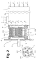
- a winding module is used in which the electrolytic solution to be desalted and the concentrate are passed tangentially through the spirally wound diluate and concentrate chambers. It is intended for a nominal capacity of typically about 400 to about 700 l / h of deionized electrolyte solution.
- the hydraulic and electrical connections of the winding module are not shown here.
- This embodiment has two ultrafiltration units 21, 22 (hollow-fiber membrane filter). These are commercially available Legionella filters, which are equipped with hollow fiber membranes with an exclusion limit of about 100,000 daltons.
- the Hollow fibers are bent in a U-shape (see above general description). The two ultrafiltration units are held on the winding module side by a connecting part 3.
- Connecting part 3 and filter holder plate 4 are located in an outer housing tube 5 made of steel, stainless steel or plastic.
- the connecting part 3 (which in the upper part of the figure is again shown as a top view of the ultrafiltration modules 21, 22) has a passage opening 6 which directs the diluate originating from the winding module to the two ultrafiltration units 21, 22.
- Within the connecting part 3 there extends a channel 7 which hydraulically connects the sockets 211, 221 of the two ultrafiltration units 21, 22 and thus forms a distribution system which distributes the diluate passing through the passage opening 6 to the two ultrafiltration units 21, 22.
- connecting part 3 and filter retaining plate 4 two spacer posts 81, 82 made of chrome steel are available.
- the composite of connecting part 3, ultrafiltration units 21, 22, filter retaining plate 4, housing tube 5 and spacers 81, 82 is cut in the figure 1 along the sectional plane AA '; their location is indicated in the connection part 3 shown again above. Due to the position of the sectional plane AA 'only one ultrafiltration module 22 and only the one spacer support 81 is visible in Figure 1; the channel 7 is therefore not visible in this sectional view.
- bores 211, 221 are provided for receiving the ultrafiltration modules; in the filter holder plate 4 are also corresponding holes (only one visible with reference numeral 222) included.
- the ultrafiltration modules 21, 22 can in the individual holes 211, 221, 222 by gluing or Welding or be firmly connected to the connecting part 3 and the filter plate 4 with sealing rings.
- the flow of the exiting from the winding module diluate thus takes place through the passage opening 6, through said distribution system in the connecting part 3, through the two ultrafiltration modules 21, 22 in parallel and then, if desired, by a corresponding, integrated into the filter holder plate collection system (not in the figure shown) and then via a likewise optional, not shown in the figure connecting piece.
- the space between connecting part 3 and filter holder plate 4 outside the ultrafiltration modules 21, 22 and the housing tube 5 is not flowed through and designed as air space.
- the inlets and outlets for the concentrate, the inflows for the electrolyte solution to be desalinated and the electrical connections are not shown in the figure; they would be outside the housing tube 5 on the front side of the device available.
- the entire device according to embodiment 1 can be installed in a preferably cylindrical casing part 9.
- This embodiment of the device according to the invention is intended for a nominal capacity of typically about 2500 to about 3300 l / h of deionized electrolyte solution.
- As electrodeionization module 1 it contains a wound module in which diluate and concentrate are passed in crossflow (with axially guided diluate).
- the axial inflows of the electrolyte solution to be desalinated are indicated by "P"("P” stands for permeate, since the added electrolyte is preferably already the permeate of an upstream, partially desalting reverse osmosis).
- P axial inflows of the electrolyte solution to be desalinated are indicated by "P"("P" stands for permeate, since the added electrolyte is preferably already the permeate of an upstream, partially desalting reverse osmosis).
- D are the axial outlets of the diluate.
- Ci designates the Concentrate Inlet and "Co” indicates Concentrate outlet.
- "+" And “-”
- the diluate outlets D of the electrodeionization module 1 open into a connection part 10 (for example made of polyoxymethylene copolymer) with a collecting space 11 and with nine passage openings for the diluate leaving the electrodeionization module 1 (only one of which is shown by reference numeral 101).
- a connection part 10 for example made of polyoxymethylene copolymer
- nine passage openings for the diluate leaving the electrodeionization module 1 (only one of which is shown by reference numeral 101).
- Each of the nine through-holes is drilled and designed so that it can be used in each case an ultrafiltration module using each a sealing ring (such as EPDM rubber or NBR).
- the total of nine ultrafiltration modules (only three of which are shown by the reference numerals 1201, 1202, 1203) are commercial legionella filters equipped with hollow fiber membranes with an exclusion limit of 100,000 Daltons.
- the hollow fibers are bent in a U-shape (see above general description).
- each ultrafiltration module 1201, 1202, 1203 The nominal maximum passage volume of each ultrafiltration module 1201, 1202, 1203 is about 800 l / h.
- the nine ultrafiltration modules are fitted between the connection part 10 and a filter support plate 14 with the aid of six chromium steel spacer supports (only one of which is shown by reference numeral 13).
- the filter retainer plate 14 again has nine apertures for the filtered permeate (only one is shown at reference numeral 15) into which the ultrafiltration modules are fitted by means of sealing rings of EPDM rubber, silicone rubber or NBR.
- the filter retaining plate 14 has on its outer side a collecting space 16 for the filtered diluate. This collecting space 16 is closed by a screwed flange 17 with central outlet 18.
- the composite of connector 10, the nine ultrafiltration modules, the six distance supports and the filter retaining plate 14 is shown cut in the figure.
- the connecting part 10 is again shown in the figure at the bottom left in the plan view, seen from the ultrafiltration modules forth; Here, the position of the cutting plane A-A ', in which said composite is shown cut indicated.
- the arrangement of all nine ultrafiltration modules is visible: six are arranged in a circular arrangement on the outside of the connecting part 3, the remaining three in the center of the connecting part 3.
- the six distance supports are shown here (only the one, cut in the sectional view visible support again provided with reference numeral 13).
- the dashed circle 11 indicates the collecting space for the diluate leaving the electrodeionization module 1; The dashed lines indicate that this collecting space is located on the back of the connecting part 10.
- the device according to embodiment 1 was also exposed to permeate from a reverse osmosis.
- the back pressure was solely generated by the two downstream ultrafiltration modules 21, 22, since there was no pressure holding valve.
- diluate was generated over 288 hours.
- the measured operating parameters are shown in FIG. As can be seen from FIG. 4, a constant water quality of 0.055-0.056 ⁇ S / cm is also achieved at a flow rate of 1000 l / h.
Landscapes
- Chemical & Material Sciences (AREA)
- Chemical Kinetics & Catalysis (AREA)
- Engineering & Computer Science (AREA)
- Water Supply & Treatment (AREA)
- Health & Medical Sciences (AREA)
- Urology & Nephrology (AREA)
- Separation Using Semi-Permeable Membranes (AREA)
- Water Treatment By Electricity Or Magnetism (AREA)
Applications Claiming Priority (1)
| Application Number | Priority Date | Filing Date | Title |
|---|---|---|---|
| CH5702006 | 2006-04-06 |
Publications (3)
| Publication Number | Publication Date |
|---|---|
| EP1842580A2 true EP1842580A2 (fr) | 2007-10-10 |
| EP1842580A3 EP1842580A3 (fr) | 2008-10-08 |
| EP1842580B1 EP1842580B1 (fr) | 2013-03-13 |
Family
ID=38283101
Family Applications (1)
| Application Number | Title | Priority Date | Filing Date |
|---|---|---|---|
| EP07007050A Active EP1842580B1 (fr) | 2006-04-06 | 2007-04-04 | Dispositif destiné au dessalage électrochimique continu avec une étape membranaire intégrée |
Country Status (4)
| Country | Link |
|---|---|
| US (2) | US20070246410A1 (fr) |
| EP (1) | EP1842580B1 (fr) |
| DK (1) | DK1842580T3 (fr) |
| NO (1) | NO20071748L (fr) |
Families Citing this family (12)
| Publication number | Priority date | Publication date | Assignee | Title |
|---|---|---|---|---|
| US12350627B2 (en) | 2013-02-28 | 2025-07-08 | Aqua Membranes, Inc. | Permeate flow patterns |
| US20150299000A1 (en) * | 2014-04-22 | 2015-10-22 | Purewater Therapeutics, LLC | Fluid handling system |
| JP2019529099A (ja) | 2016-09-20 | 2019-10-17 | アクア メンブレインズ エルエルシー | 透過流パターン |
| KR102033982B1 (ko) | 2016-11-19 | 2019-10-18 | 아쿠아 멤브레인스 엘엘씨 | 나선형 권취 요소를 위한 간섭 패턴 |
| WO2018190937A1 (fr) | 2017-04-12 | 2018-10-18 | Aqua Membranes Llc | Éléments d'espacement à gradient destinés à des éléments de filtration pour plaie |
| WO2018195367A1 (fr) | 2017-04-20 | 2018-10-25 | Aqua Membranes Llc | Motifs d'espacement favorisant le mélange pour éléments enroulés en spirale |
| CN120094407A (zh) | 2017-04-20 | 2025-06-06 | 阿夸曼布拉尼斯公司 | 用于螺旋卷绕元件的不嵌套、不变形图案 |
| CN111344053A (zh) | 2017-10-13 | 2020-06-26 | 阿夸曼布拉尼斯公司 | 螺旋缠绕元件的桥支撑件和减少的进给间隔件 |
| WO2020154734A1 (fr) | 2019-01-27 | 2020-07-30 | Aqua Membranes Inc. | Membranes composites |
| US12303838B2 (en) | 2019-08-06 | 2025-05-20 | Aqua Membranes, Inc. | Preferred flow paths for spiral-wound elements |
| US11633700B2 (en) | 2020-04-07 | 2023-04-25 | Aqua Membranes Inc. | Independent spacers and methods |
| CN118742376B (zh) | 2021-12-28 | 2025-12-05 | 阿夸曼布拉尼斯公司 | 具有保护特征的高截留率螺旋卷绕元件 |
Family Cites Families (18)
| Publication number | Priority date | Publication date | Assignee | Title |
|---|---|---|---|---|
| US2376253A (en) | 1944-04-07 | 1945-05-15 | Doughboy Machines Inc | Sealing machine |
| US4465573A (en) * | 1981-05-12 | 1984-08-14 | Hare Harry M O | Method and apparatus for the purification of water |
| US4925541B1 (en) * | 1984-07-09 | 1994-08-02 | Millipore Corp | Electrodeionization apparatus and method |
| US5045198A (en) * | 1989-08-04 | 1991-09-03 | Culligan International Company | Faucet-mounted microbial filter |
| US5116509A (en) * | 1989-09-08 | 1992-05-26 | Millipore Corporation | Electrodeionization and ultraviolet light treatment method for purifying water |
| US5114582A (en) * | 1991-04-12 | 1992-05-19 | W. R. Grace & Co.-Conn. | Filter element and spiral-wound membrane cartridge containing same |
| ES2092267T3 (es) * | 1992-05-15 | 1996-11-16 | Christ Ag | Dispositivo para la desalinizacion electroquimica continua de soluciones acuosas. |
| US6190528B1 (en) * | 1998-03-19 | 2001-02-20 | Xiang Li | Helical electrodeionization apparatus |
| WO2000071227A1 (fr) * | 1999-05-21 | 2000-11-30 | Life Spring Limited Partnership | Ensemble de traitement de l'eau a ultraviolets commande par l'usager |
| JP3570304B2 (ja) * | 1999-08-11 | 2004-09-29 | 栗田工業株式会社 | 脱イオン水製造装置の殺菌方法及び脱イオン水の製造方法 |
| JP3794268B2 (ja) * | 2001-01-05 | 2006-07-05 | 栗田工業株式会社 | 電気脱イオン装置及びその運転方法 |
| DE10115633A1 (de) * | 2001-03-23 | 2002-09-26 | Fuma Tech Gmbh | Gewinnung von im wesentlichen keimfreiem Wasser |
| JP4072323B2 (ja) * | 2001-04-27 | 2008-04-09 | シャープ株式会社 | ガリウム砒素含有排水の処理方法およびガリウム砒素含有排水の処理装置 |
| US6649037B2 (en) * | 2001-05-29 | 2003-11-18 | United States Filter Corporation | Electrodeionization apparatus and method |
| ATE497830T1 (de) * | 2001-10-15 | 2011-02-15 | Siemens Water Tech Holdg Corp | Vorrichtung und verfahren zur reinigung von flüssigkeiten |
| EP1329425A1 (fr) * | 2002-01-18 | 2003-07-23 | Toray Industries, Inc. | Procédé et appareil de dessalement |
| US7927478B2 (en) | 2003-05-17 | 2011-04-19 | P & Ls Holding Gmbh | Spiral wound module having axial dilution chamber flow |
| CA2742081A1 (fr) * | 2008-10-31 | 2010-05-06 | Jacob Telepciak | Bloc collecteur pour systemes d'osmose inverse |
-
2007
- 2007-04-02 NO NO20071748A patent/NO20071748L/no not_active Application Discontinuation
- 2007-04-04 EP EP07007050A patent/EP1842580B1/fr active Active
- 2007-04-04 DK DK07007050.3T patent/DK1842580T3/da active
- 2007-04-04 US US11/696,474 patent/US20070246410A1/en not_active Abandoned
-
2012
- 2012-09-25 US US13/626,094 patent/US8652326B2/en active Active
Also Published As
| Publication number | Publication date |
|---|---|
| EP1842580A3 (fr) | 2008-10-08 |
| US20070246410A1 (en) | 2007-10-25 |
| US8652326B2 (en) | 2014-02-18 |
| DK1842580T3 (da) | 2013-06-10 |
| EP1842580B1 (fr) | 2013-03-13 |
| US20130020260A1 (en) | 2013-01-24 |
| NO20071748L (no) | 2007-10-08 |
Similar Documents
| Publication | Publication Date | Title |
|---|---|---|
| EP1842580B1 (fr) | Dispositif destiné au dessalage électrochimique continu avec une étape membranaire intégrée | |
| DE69738497T2 (de) | Verbesserte filtrationsanordnung mit mikroporöser membrane | |
| DE69527021T2 (de) | Vorrichtung und Verfahren zum Entsalzen von Meerwasser durch mehrstufige Umkehrosmose | |
| DE69934701T2 (de) | Verfahren zur Behandlung von Fluida | |
| EP0947237B1 (fr) | Dispositif de séparation de milieux liquides chargés d'impuretés | |
| DE19827473C1 (de) | Verbesserte Crossflow-Filterkassetten | |
| EP4509206B1 (fr) | Filtration tangentielle pour diafiltration continue | |
| EP4061517B1 (fr) | Appareil de filtration | |
| AT513225B1 (de) | Verfahren zur Filtration von Flüssigkeiten | |
| WO2002022244A1 (fr) | Filtre a membrane pour traitement de l'eau | |
| DE8990025U1 (de) | Spiralförmig gewickelte Membranzelle für Umkehrosmose | |
| DE2424853A1 (de) | Verfahren und vorrichtung zur aufbereitung von molke | |
| DE2525972A1 (de) | Vorrichtung zur durchfuehrung der membranfiltration | |
| DE19982837B4 (de) | Elektrodialysevorrichtung | |
| EP2608873B1 (fr) | Une unité de filière, une méthode pour produire une membrane multicanaux avec l'unité de filière et l'utilisation de l'unité de filière | |
| EP2352702B1 (fr) | Procédé de traitement de l'eau et dispositif séparateur à membrane convenant pour celui-ci, ainsi qu'installation de traitement de l'eau | |
| EP0592698B1 (fr) | Séparateur par ultrafiltration | |
| DE102019132699A1 (de) | Vorrichtung zur Filterung von Bestandteilen aus einem Fluid | |
| EP3241806B1 (fr) | Dispositif de filtre terminal destiné à réduire les impuretés microbiologiques dans un milieu aqueux | |
| DE2652605A1 (de) | Membranmodul fuer die umgekehrte osmose oder ultrafiltration | |
| WO2001096002A1 (fr) | Dispositif de filtration transversale de liquides | |
| DE102016108866B4 (de) | Modularer Ionentauscher | |
| EP0675761B1 (fr) | Procede et installation permettant de traiter une solution aqueuse par echange d'ions | |
| DE4143423C2 (de) | Ultrafiltrationsvorrichtung | |
| DE3228784A1 (de) | Verfahren, anordnung und vorrichtung zur ueberwachung des stofftransports in einer membrantrennanlage |
Legal Events
| Date | Code | Title | Description |
|---|---|---|---|
| PUAI | Public reference made under article 153(3) epc to a published international application that has entered the european phase |
Free format text: ORIGINAL CODE: 0009012 |
|
| AK | Designated contracting states |
Kind code of ref document: A2 Designated state(s): AT BE BG CH CY CZ DE DK EE ES FI FR GB GR HU IE IS IT LI LT LU LV MC MT NL PL PT RO SE SI SK TR |
|
| AX | Request for extension of the european patent |
Extension state: AL BA HR MK YU |
|
| RIN1 | Information on inventor provided before grant (corrected) |
Inventor name: BRAND, CHRISTIAN Inventor name: JOHANN, JUERGEN Inventor name: BISSEN, MONIQUE Inventor name: MENZEL, THOMAS Inventor name: SCHRAMM, THOMAS |
|
| RAP1 | Party data changed (applicant data changed or rights of an application transferred) |
Owner name: CHRIST WATER TECHNOLOGY AG |
|
| PUAL | Search report despatched |
Free format text: ORIGINAL CODE: 0009013 |
|
| AK | Designated contracting states |
Kind code of ref document: A3 Designated state(s): AT BE BG CH CY CZ DE DK EE ES FI FR GB GR HU IE IS IT LI LT LU LV MC MT NL PL PT RO SE SI SK TR |
|
| AX | Request for extension of the european patent |
Extension state: AL BA HR MK RS |
|
| RIC1 | Information provided on ipc code assigned before grant |
Ipc: B01D 63/02 20060101ALN20080829BHEP Ipc: B01D 61/14 20060101ALI20080829BHEP Ipc: B01D 63/10 20060101ALI20080829BHEP Ipc: B01D 61/58 20060101AFI20070730BHEP Ipc: B01D 61/48 20060101ALI20080829BHEP |
|
| 17P | Request for examination filed |
Effective date: 20090327 |
|
| AKX | Designation fees paid |
Designated state(s): AT BE BG CH CY CZ DE DK EE ES FI FR GB GR HU IE IS IT LI LT LU LV MC MT NL PL PT RO SE SI SK TR |
|
| RAP1 | Party data changed (applicant data changed or rights of an application transferred) |
Owner name: P & LS HOLDING GMBH |
|
| 17Q | First examination report despatched |
Effective date: 20110323 |
|
| GRAP | Despatch of communication of intention to grant a patent |
Free format text: ORIGINAL CODE: EPIDOSNIGR1 |
|
| GRAS | Grant fee paid |
Free format text: ORIGINAL CODE: EPIDOSNIGR3 |
|
| GRAA | (expected) grant |
Free format text: ORIGINAL CODE: 0009210 |
|
| AK | Designated contracting states |
Kind code of ref document: B1 Designated state(s): AT BE BG CH CY CZ DE DK EE ES FI FR GB GR HU IE IS IT LI LT LU LV MC MT NL PL PT RO SE SI SK TR |
|
| REG | Reference to a national code |
Ref country code: GB Ref legal event code: FG4D Free format text: NOT ENGLISH |
|
| REG | Reference to a national code |
Ref country code: CH Ref legal event code: EP Ref country code: AT Ref legal event code: REF Ref document number: 600452 Country of ref document: AT Kind code of ref document: T Effective date: 20130315 |
|
| REG | Reference to a national code |
Ref country code: IE Ref legal event code: FG4D Free format text: LANGUAGE OF EP DOCUMENT: GERMAN |
|
| REG | Reference to a national code |
Ref country code: DE Ref legal event code: R096 Ref document number: 502007011434 Country of ref document: DE Effective date: 20130508 |
|
| REG | Reference to a national code |
Ref country code: DK Ref legal event code: T3 |
|
| REG | Reference to a national code |
Ref country code: CH Ref legal event code: NV Representative=s name: BOHEST AG, CH |
|
| REG | Reference to a national code |
Ref country code: SE Ref legal event code: TRGR |
|
| PG25 | Lapsed in a contracting state [announced via postgrant information from national office to epo] |
Ref country code: LT Free format text: LAPSE BECAUSE OF FAILURE TO SUBMIT A TRANSLATION OF THE DESCRIPTION OR TO PAY THE FEE WITHIN THE PRESCRIBED TIME-LIMIT Effective date: 20130313 Ref country code: BG Free format text: LAPSE BECAUSE OF FAILURE TO SUBMIT A TRANSLATION OF THE DESCRIPTION OR TO PAY THE FEE WITHIN THE PRESCRIBED TIME-LIMIT Effective date: 20130613 Ref country code: ES Free format text: LAPSE BECAUSE OF FAILURE TO SUBMIT A TRANSLATION OF THE DESCRIPTION OR TO PAY THE FEE WITHIN THE PRESCRIBED TIME-LIMIT Effective date: 20130624 |
|
| PGFP | Annual fee paid to national office [announced via postgrant information from national office to epo] |
Ref country code: IE Payment date: 20130530 Year of fee payment: 7 Ref country code: DK Payment date: 20130618 Year of fee payment: 7 |
|
| REG | Reference to a national code |
Ref country code: NL Ref legal event code: T3 |
|
| REG | Reference to a national code |
Ref country code: LT Ref legal event code: MG4D |
|
| PG25 | Lapsed in a contracting state [announced via postgrant information from national office to epo] |
Ref country code: SI Free format text: LAPSE BECAUSE OF FAILURE TO SUBMIT A TRANSLATION OF THE DESCRIPTION OR TO PAY THE FEE WITHIN THE PRESCRIBED TIME-LIMIT Effective date: 20130313 Ref country code: GR Free format text: LAPSE BECAUSE OF FAILURE TO SUBMIT A TRANSLATION OF THE DESCRIPTION OR TO PAY THE FEE WITHIN THE PRESCRIBED TIME-LIMIT Effective date: 20130614 Ref country code: LV Free format text: LAPSE BECAUSE OF FAILURE TO SUBMIT A TRANSLATION OF THE DESCRIPTION OR TO PAY THE FEE WITHIN THE PRESCRIBED TIME-LIMIT Effective date: 20130313 Ref country code: FI Free format text: LAPSE BECAUSE OF FAILURE TO SUBMIT A TRANSLATION OF THE DESCRIPTION OR TO PAY THE FEE WITHIN THE PRESCRIBED TIME-LIMIT Effective date: 20130313 |
|
| PG25 | Lapsed in a contracting state [announced via postgrant information from national office to epo] |
Ref country code: CZ Free format text: LAPSE BECAUSE OF FAILURE TO SUBMIT A TRANSLATION OF THE DESCRIPTION OR TO PAY THE FEE WITHIN THE PRESCRIBED TIME-LIMIT Effective date: 20130313 Ref country code: PT Free format text: LAPSE BECAUSE OF FAILURE TO SUBMIT A TRANSLATION OF THE DESCRIPTION OR TO PAY THE FEE WITHIN THE PRESCRIBED TIME-LIMIT Effective date: 20130715 Ref country code: RO Free format text: LAPSE BECAUSE OF FAILURE TO SUBMIT A TRANSLATION OF THE DESCRIPTION OR TO PAY THE FEE WITHIN THE PRESCRIBED TIME-LIMIT Effective date: 20130313 Ref country code: SK Free format text: LAPSE BECAUSE OF FAILURE TO SUBMIT A TRANSLATION OF THE DESCRIPTION OR TO PAY THE FEE WITHIN THE PRESCRIBED TIME-LIMIT Effective date: 20130313 Ref country code: EE Free format text: LAPSE BECAUSE OF FAILURE TO SUBMIT A TRANSLATION OF THE DESCRIPTION OR TO PAY THE FEE WITHIN THE PRESCRIBED TIME-LIMIT Effective date: 20130313 Ref country code: IS Free format text: LAPSE BECAUSE OF FAILURE TO SUBMIT A TRANSLATION OF THE DESCRIPTION OR TO PAY THE FEE WITHIN THE PRESCRIBED TIME-LIMIT Effective date: 20130713 |
|
| PG25 | Lapsed in a contracting state [announced via postgrant information from national office to epo] |
Ref country code: CY Free format text: LAPSE BECAUSE OF FAILURE TO SUBMIT A TRANSLATION OF THE DESCRIPTION OR TO PAY THE FEE WITHIN THE PRESCRIBED TIME-LIMIT Effective date: 20130313 Ref country code: PL Free format text: LAPSE BECAUSE OF FAILURE TO SUBMIT A TRANSLATION OF THE DESCRIPTION OR TO PAY THE FEE WITHIN THE PRESCRIBED TIME-LIMIT Effective date: 20130313 |
|
| PG25 | Lapsed in a contracting state [announced via postgrant information from national office to epo] |
Ref country code: MC Free format text: LAPSE BECAUSE OF FAILURE TO SUBMIT A TRANSLATION OF THE DESCRIPTION OR TO PAY THE FEE WITHIN THE PRESCRIBED TIME-LIMIT Effective date: 20130313 |
|
| PLBE | No opposition filed within time limit |
Free format text: ORIGINAL CODE: 0009261 |
|
| STAA | Information on the status of an ep patent application or granted ep patent |
Free format text: STATUS: NO OPPOSITION FILED WITHIN TIME LIMIT |
|
| 26N | No opposition filed |
Effective date: 20131216 |
|
| PG25 | Lapsed in a contracting state [announced via postgrant information from national office to epo] |
Ref country code: IT Free format text: LAPSE BECAUSE OF FAILURE TO SUBMIT A TRANSLATION OF THE DESCRIPTION OR TO PAY THE FEE WITHIN THE PRESCRIBED TIME-LIMIT Effective date: 20130313 |
|
| REG | Reference to a national code |
Ref country code: DE Ref legal event code: R097 Ref document number: 502007011434 Country of ref document: DE Effective date: 20131216 |
|
| REG | Reference to a national code |
Ref country code: AT Ref legal event code: MM01 Ref document number: 600452 Country of ref document: AT Kind code of ref document: T Effective date: 20130404 |
|
| REG | Reference to a national code |
Ref country code: CH Ref legal event code: PCAR Free format text: NEW ADDRESS: HOLBEINSTRASSE 36-38, 4051 BASEL (CH) |
|
| PG25 | Lapsed in a contracting state [announced via postgrant information from national office to epo] |
Ref country code: AT Free format text: LAPSE BECAUSE OF NON-PAYMENT OF DUE FEES Effective date: 20130404 |
|
| REG | Reference to a national code |
Ref country code: DK Ref legal event code: EBP Effective date: 20140430 |
|
| REG | Reference to a national code |
Ref country code: IE Ref legal event code: MM4A |
|
| PG25 | Lapsed in a contracting state [announced via postgrant information from national office to epo] |
Ref country code: MT Free format text: LAPSE BECAUSE OF FAILURE TO SUBMIT A TRANSLATION OF THE DESCRIPTION OR TO PAY THE FEE WITHIN THE PRESCRIBED TIME-LIMIT Effective date: 20130313 |
|
| PG25 | Lapsed in a contracting state [announced via postgrant information from national office to epo] |
Ref country code: DK Free format text: LAPSE BECAUSE OF NON-PAYMENT OF DUE FEES Effective date: 20140430 Ref country code: IE Free format text: LAPSE BECAUSE OF NON-PAYMENT OF DUE FEES Effective date: 20140404 |
|
| PG25 | Lapsed in a contracting state [announced via postgrant information from national office to epo] |
Ref country code: TR Free format text: LAPSE BECAUSE OF FAILURE TO SUBMIT A TRANSLATION OF THE DESCRIPTION OR TO PAY THE FEE WITHIN THE PRESCRIBED TIME-LIMIT Effective date: 20130313 |
|
| PG25 | Lapsed in a contracting state [announced via postgrant information from national office to epo] |
Ref country code: LU Free format text: LAPSE BECAUSE OF NON-PAYMENT OF DUE FEES Effective date: 20130404 Ref country code: HU Free format text: LAPSE BECAUSE OF FAILURE TO SUBMIT A TRANSLATION OF THE DESCRIPTION OR TO PAY THE FEE WITHIN THE PRESCRIBED TIME-LIMIT; INVALID AB INITIO Effective date: 20070404 |
|
| REG | Reference to a national code |
Ref country code: FR Ref legal event code: PLFP Year of fee payment: 10 |
|
| REG | Reference to a national code |
Ref country code: FR Ref legal event code: PLFP Year of fee payment: 11 |
|
| REG | Reference to a national code |
Ref country code: FR Ref legal event code: PLFP Year of fee payment: 12 |
|
| P01 | Opt-out of the competence of the unified patent court (upc) registered |
Effective date: 20230419 |
|
| PGFP | Annual fee paid to national office [announced via postgrant information from national office to epo] |
Ref country code: NL Payment date: 20250411 Year of fee payment: 19 |
|
| PGFP | Annual fee paid to national office [announced via postgrant information from national office to epo] |
Ref country code: DE Payment date: 20250411 Year of fee payment: 19 |
|
| PGFP | Annual fee paid to national office [announced via postgrant information from national office to epo] |
Ref country code: GB Payment date: 20250408 Year of fee payment: 19 |
|
| PGFP | Annual fee paid to national office [announced via postgrant information from national office to epo] |
Ref country code: BE Payment date: 20250408 Year of fee payment: 19 |
|
| PGFP | Annual fee paid to national office [announced via postgrant information from national office to epo] |
Ref country code: FR Payment date: 20250408 Year of fee payment: 19 |
|
| PGFP | Annual fee paid to national office [announced via postgrant information from national office to epo] |
Ref country code: CH Payment date: 20250501 Year of fee payment: 19 |
|
| PGFP | Annual fee paid to national office [announced via postgrant information from national office to epo] |
Ref country code: SE Payment date: 20250408 Year of fee payment: 19 |