EP1842702A1 - Luftverteilsystem mit berührungsloser Betätigung der Düsen - Google Patents
Luftverteilsystem mit berührungsloser Betätigung der Düsen Download PDFInfo
- Publication number
- EP1842702A1 EP1842702A1 EP06425239A EP06425239A EP1842702A1 EP 1842702 A1 EP1842702 A1 EP 1842702A1 EP 06425239 A EP06425239 A EP 06425239A EP 06425239 A EP06425239 A EP 06425239A EP 1842702 A1 EP1842702 A1 EP 1842702A1
- Authority
- EP
- European Patent Office
- Prior art keywords
- air outlet
- air
- activated
- condition
- designed
- Prior art date
- Legal status (The legal status is an assumption and is not a legal conclusion. Google has not performed a legal analysis and makes no representation as to the accuracy of the status listed.)
- Granted
Links
Images

Classifications
-
- B—PERFORMING OPERATIONS; TRANSPORTING
- B60—VEHICLES IN GENERAL
- B60H—ARRANGEMENTS OF HEATING, COOLING, VENTILATING OR OTHER AIR-TREATING DEVICES SPECIALLY ADAPTED FOR PASSENGER OR GOODS SPACES OF VEHICLES
- B60H1/00—Heating, cooling or ventilating devices
- B60H1/00642—Control systems or circuits; Control members or indication devices for heating, cooling or ventilating devices
- B60H1/00814—Control systems or circuits characterised by their output, for controlling particular components of the heating, cooling or ventilating installation
- B60H1/00821—Control systems or circuits characterised by their output, for controlling particular components of the heating, cooling or ventilating installation the components being ventilating, air admitting or air distributing devices
- B60H1/00871—Air directing means, e.g. blades in an air outlet
-
- B—PERFORMING OPERATIONS; TRANSPORTING
- B60—VEHICLES IN GENERAL
- B60H—ARRANGEMENTS OF HEATING, COOLING, VENTILATING OR OTHER AIR-TREATING DEVICES SPECIALLY ADAPTED FOR PASSENGER OR GOODS SPACES OF VEHICLES
- B60H1/00—Heating, cooling or ventilating devices
- B60H1/00642—Control systems or circuits; Control members or indication devices for heating, cooling or ventilating devices
- B60H1/00735—Control systems or circuits characterised by their input, i.e. by the detection, measurement or calculation of particular conditions, e.g. signal treatment, dynamic models
- B60H1/00742—Control systems or circuits characterised by their input, i.e. by the detection, measurement or calculation of particular conditions, e.g. signal treatment, dynamic models by detection of the vehicle occupants' presence; by detection of conditions relating to the body of occupants, e.g. using radiant heat detectors
-
- B—PERFORMING OPERATIONS; TRANSPORTING
- B60—VEHICLES IN GENERAL
- B60H—ARRANGEMENTS OF HEATING, COOLING, VENTILATING OR OTHER AIR-TREATING DEVICES SPECIALLY ADAPTED FOR PASSENGER OR GOODS SPACES OF VEHICLES
- B60H1/00—Heating, cooling or ventilating devices
- B60H1/34—Nozzles; Air-diffusers
- B60H2001/3471—Details of actuators
Definitions
- the present invention relates to systems for air distribution, in particular into the passenger compartment of a vehicle, for example, a motor vehicle, of the type comprising at least one outlet for outflow of air into the passenger compartment, a duct for supplying a flow of air to said air outlet, and means for activating the air outlet, i.e., for controlling opening of said air outlet and/or for enabling supply of a flow of air to the air outlet through said duct, in which the aforesaid activation means include a proximity sensor, which is associated to said air outlet in a position adjacent thereto and is designed to issue at output an electrical signal for activation of the air outlet following upon detection of the presence of a body at a short distance from the air outlet.
- a proximity sensor which is associated to said air outlet in a position adjacent thereto and is designed to issue at output an electrical signal for activation of the air outlet following upon detection of the presence of a body at a short distance from the air outlet.
- a system of the type described above is known from the document No. US 2002/072321 .
- a hatch associated to an air outlet is automatically opened following upon detection of the body of an occupant of the seat in front of the air outlet and can be reclosed only manually.
- activation of the sensor associated to the air outlet cannot be controlled by the occupant, in so far as it occurs in any case once the occupant occupies the seat.
- the purpose of the present invention is to provide a system of the type already proposed by the present applicant that will be particularly simple and inexpensive to produce, whilst at the same time being efficient as regards operation as well as convenient to use.
- the subject of the invention is an air-distribution system of the type already proposed in the preceding European patent application No. EP 04425861.4 filed in the name of the present applicant and further characterized in that said sensor is set at a distance from said air outlet and is optically connected to a window adjacent to the air outlet via a light guide.
- said light guide is an optical fibre.
- the senor comprises an optical emitter, designed to emit an optical signal through said light guide and at output from said window, and an optical receiver, designed to receive radiation reflected by a body set in front of said window, the reflected radiation returning through said window and through said light guide.
- said emitter and said receiver are an infrared emitter and an infrared detector.
- the emitter is controlled by said electronic control unit in such a way as to emit an encoded optical signal
- said electronic control unit is connected to said receiver and is programmed for distinguishing between the optical signals received by said receiver, following upon a reflection of the signal issued by said emitter, from the optical signals due to other causes.
- the air outlet is prevented from accidentally switching its state, for example on account of a ray of light coming from outside.
- said light guide is also used for conveying the light emitted by light-source means (for example, a LED) as far as said window, and said light-source means are controlled by said electronic control unit in such a way as to cause a switching of state (off/on) or cause a colour switching according to the condition (activated/de-activated) of the air outlet.
- light-source means for example, a LED
- said electronic control unit controls said electronic control unit in such a way as to cause a switching of state (off/on) or cause a colour switching according to the condition (activated/de-activated) of the air outlet.
- the actuator is designed to drive displacement of a plurality of oscillating slats or other mechanical closing means associated to the air outlet between the condition of closing and the condition of opening of the air outlet.
- said actuator is instead designed to deflect in the aforesaid supply duct a flow of air coming from a source for supply of conditioned air.
- the invention can be applied both to air outlets for airing the passenger compartment of a motor vehicle and to air outlets for airing the passenger compartment of an aircraft, or else to air outlets for airing an environment in a building.
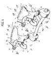
- the air-distribution system illustrated in Figure 1 is of the type forming the subject of the European patent application No. EP-A-1544005 filed in the name of the present applicant. It should be noted, however, that the present invention is of general application and can, consequently, be employed in any system for air distribution in the passenger compartment of a motor vehicle, as likewise in the field of vehicles in general.
- a system of the type described above can also be used, for example, for controlling the outlets for outflow of air into the passenger compartment of an aircraft or of a boat or of a dwelling or building in general.
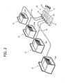
- the reference number 1 designates as a whole an air-distribution system associated to the dashboard 2 (illustrated only partially in Figure 2) of a motor vehicle.
- the distribution system 1 comprises a main duct 4, which receives air from a conditioning system, including a main fan (not illustrated) and a heater/evaporator (not illustrated).
- the main duct 4 gives out into a manifold or rail 6, from which there branch off four auxiliary ducts 7 (only two of which may be seen in Figure 1) distributed in parallel along the dashboard, one pair on the driver side, and one pair on the passenger side, each pair comprising a duct adjacent to the central part of the dashboard and a duct closer to a side window of the motor vehicle.
- Each auxiliary duct 7 branches into three terminal ducts 8, 9, 10, each of which terminates on outlets for outflow of air into the passenger compartment of a motor vehicle.
- the duct 8 supplies air outlets 11 arranged at the base of the windscreen so as to direct the flow of air on the internal surface of the windscreen itself.
- the duct 9 terminates on one or more air outlets 12 arranged at the front on the dashboard so as to direct air into the passenger compartment of the motor vehicle, and the duct 10 terminates on one or more air outlets 13, which direct a flow of air towards the floor of the passenger compartment.
- each auxiliary duct 7 branches into the three terminal ducts 8, 9, 10 are means for distributing the flow of air between the terminal ducts.
- Said means can be constituted, in a way in itself known, by louvers for deviation of the flow (not illustrated) or else, according to a technology developed by the present applicant and forming the subject of a wide range of prior patents, can be constituted by elements designed to cause deviation of the air flow by the Coanda effect.
- a solution of this type is, for example, described and illustrated in the international patent application No. WO 2004/065149 filed in the name of the present applicant.
- each of the auxiliary ducts 7 is provided with an additional and independent unit for adjustment of at least one characteristic of the air flow.
- a unit 14 for adjusting the air flowrate and a unit 15 for adjusting the temperature of the air.
- the unit 14 comprises a fan with corresponding electric control motor
- the unit 15 comprises a section of duct, inserted in which is an electrical resistance.
- the distribution system 1 enables adjustment of the flowrate and/or the temperature of the flow of air leaving the air outlets 11, 12, 13, separately for each of the auxiliary ducts 7, i.e., once again in the case of the example illustrated, separately for the driver area and for the passenger area and, for each of said areas, separately for the central area of the dashboard and for the area adjacent to the window.
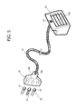
- each outlet 12 for outflow of air into the passenger compartment of the motor vehicle is associated to an optical sensor, which is designed to cause automatic switching of the air outlet from the condition in which it is found (open or closed) to the opposite condition when a body is set at a short distance in front of it so that the air outlet can be switched from the open condition to the closed condition or vice versa, for example, when a hand is put at a short distance in front of it, without touching it, as illustrated in Figure 6 of the annexed drawings.
- the system according to the invention uses a sensor, which is set at distance from the respective air outlet and is optically connected to a window adjacent to the air outlet via a light guide, specifically an optical fibre.
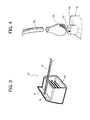
- the window associated to each air outlet 12 is designated by the reference number 16 and is constituted by a hole 17 (see Figure 3) made in a wall 18, which projects at the top from the body of the air outlet 12 and is preferably provided with a transparent protection element 16a, possibly provided with optical properties and made, for example, of plastic material.
- a transparent protection element 16a possibly provided with optical properties and made, for example, of plastic material.
- Mounted within the hole 17 by interference fit is the end of an optical fibre 19 which optically couples the window 16 to a sensor assembly, designated as a whole by the reference number 20.
- each sensor assembly 20 associated to each air outlet 12 includes an emitter source of infrared light 21 (for example, a LED), and an infrared receiver-detector 22.
- the emitter 21 and the detector 22 are optically coupled, via an optical-coupling device 23 of the known type referred to as "triplexer", to the same optical fibre 19, in such a way that the infrared radiation emitted by the emitter 21 traverses the optical fibre 19 (see the arrows in Figure 6), comes out from the window 16, and, if reflected by a foreign body such as the hand M purposely set by the user in front of the air outlet 12, returns through the window 16 and again traverses in the opposite direction the optical fibre 19 until it is received by the detector 22.
- an optical-coupling device 23 of the known type referred to as "triplexer”
- the triplexer device 23 also connects to the optical fibre 19 a light source 24, which lights up the window 16 through the optical fibre 19.
- the light source 24 is designed to provide the user with the possibility of checking whether the air outlet is in the activated condition or in the de-activated condition simply by looking at the window 16. For example, it is possible to envisage that the source 24 lights up when the air outlet is activated and is off when the air outlet is de-activated, or else that it changes colour (for example, between red and green) according to the condition of the air outlet.
- a sheath 23c for example made of rubber and having a substantially tubular shape, has one end fitted around the optical fibre 19 and the opposite end fitted around the neck 23b.
- the triplexer devices 23 associated to the various air outlets are fitted on top of a supporting structure 24, which incorporates the electrical connections of the emitter 21, of the detector 22, and of the light source 24 associated to each triplexer 23 with an electronic control unit 25.
- the electronic control unit 25 is connected to the devices 21, 22, 24 optically coupled to each air outlet 12 and controls entry into action of actuator means 26 constituted by a plurality of separate actuators, each designed to control the activated condition or de-activated condition of each air outlet 12.
- activation of the air outlet can consist in controlling opening or closing of a plurality of orientable slats 12a ( Figure 6) with which the air outlet is provided and/or activation of a device designed to enable a flow of air to reach the air outlet, for example, constituted by a fan, or else by a deflector of the flow of air in the aeration system, for instance, of the Coanda-effect type described in the prior patent applications cited above filed in the name of the present applicant.
- the electronic control unit 25 controls the actuator associated to each air outlet 12 whenever the user puts, for example, a hand in front of the air outlet to bring about its change of state (from activated to de-activated or vice versa).
- the electronic control unit 25 controls the light source 24 associated to each air outlet so as to supply an optical information indicating the state of the air outlet, which enables the user to ascertain said state without any direct check, and in particular without the need to put a hand in front of the air outlet to check whether a flow of air comes out therefrom, which could cause an undesirable switching of state of the air outlet.
- the electronic control unit 25 is designed to control each emitter 21 in such a way that the emitter 21 emits infrared radiation according to an encoded pulse sequence.
- the same electronic control unit is also designed to check that the reflected radiation received by the detector 22 corresponds to the same encoded sequence of pulses so as to enable switching of state of the air outlet 12.
- the electronic control unit 25 is consequently able to distinguish the signals received by the detector 22 that depend on the user's desire to cause switching of state the air outlet from optical signals due to other reasons, for example rays of light coming from the outside of the motor vehicle that impinge upon the window of the air outlet. Any risk of the air outlet being accidentally governed by extraneous factors contrary to the intention of the user is thus prevented.
Landscapes
- Physics & Mathematics (AREA)
- Thermal Sciences (AREA)
- Engineering & Computer Science (AREA)
- Mechanical Engineering (AREA)
- Air-Conditioning For Vehicles (AREA)
- Spinning Or Twisting Of Yarns (AREA)
- Duct Arrangements (AREA)
- Electrical Discharge Machining, Electrochemical Machining, And Combined Machining (AREA)
Priority Applications (4)
| Application Number | Priority Date | Filing Date | Title |
|---|---|---|---|
| AT06425239T ATE390309T1 (de) | 2006-04-05 | 2006-04-05 | Luftverteilsystem mit berührungsloser betätigung der düsen |
| EP06425239A EP1842702B1 (de) | 2006-04-05 | 2006-04-05 | Luftverteilsystem mit berührungsloser Betätigung der Düsen |
| DE602006000824T DE602006000824T2 (de) | 2006-04-05 | 2006-04-05 | Luftverteilsystem mit berührungsloser Betätigung der Düsen |
| US11/695,910 US8210913B2 (en) | 2006-04-05 | 2007-04-03 | Air-distribution system, with contactless activation of air outlets |
Applications Claiming Priority (1)
| Application Number | Priority Date | Filing Date | Title |
|---|---|---|---|
| EP06425239A EP1842702B1 (de) | 2006-04-05 | 2006-04-05 | Luftverteilsystem mit berührungsloser Betätigung der Düsen |
Publications (2)
| Publication Number | Publication Date |
|---|---|
| EP1842702A1 true EP1842702A1 (de) | 2007-10-10 |
| EP1842702B1 EP1842702B1 (de) | 2008-03-26 |
Family
ID=36699023
Family Applications (1)
| Application Number | Title | Priority Date | Filing Date |
|---|---|---|---|
| EP06425239A Expired - Lifetime EP1842702B1 (de) | 2006-04-05 | 2006-04-05 | Luftverteilsystem mit berührungsloser Betätigung der Düsen |
Country Status (4)
| Country | Link |
|---|---|
| US (1) | US8210913B2 (de) |
| EP (1) | EP1842702B1 (de) |
| AT (1) | ATE390309T1 (de) |
| DE (1) | DE602006000824T2 (de) |
Families Citing this family (18)
| Publication number | Priority date | Publication date | Assignee | Title |
|---|---|---|---|---|
| JP5071159B2 (ja) * | 2008-02-29 | 2012-11-14 | 富士通株式会社 | 情報機器 |
| US20090308565A1 (en) * | 2008-06-13 | 2009-12-17 | Jones Robert G | Cart occupant cooling system |
| DE102010018105B4 (de) | 2010-04-24 | 2021-06-24 | Volkswagen Ag | Fahrzeugcockpit mit einer Bedieneinrichtung zum Erfassen von Nutzereingaben und Verfahren zum Betreiben einer solchen |
| US20130037252A1 (en) * | 2011-08-12 | 2013-02-14 | GM Global Technology Operations LLC | Smart hvac system having occupant detection capability |
| US20150025738A1 (en) * | 2013-07-22 | 2015-01-22 | GM Global Technology Operations LLC | Methods and apparatus for automatic climate control in a vehicle based on clothing insulative factor |
| DE102013019197A1 (de) * | 2013-11-15 | 2015-05-21 | Audi Ag | Kraftfahrzeug-Klimatisierung mit adaptivem Luftausströmer |
| DE102014206215B4 (de) | 2014-04-01 | 2024-09-26 | Audi Ag | Verfahren und Vorrichtung zur Steuerung mindestens eines Luftstroms zur lokalen Beheizung und/oder Klimatisierung in einem Fahrzeug |
| US10449828B2 (en) | 2014-05-15 | 2019-10-22 | ValTec, LLC | System for controlling air flow into the passenger compartment of a vehicle |
| US9840128B2 (en) * | 2015-03-10 | 2017-12-12 | Ford Global Technologies, Llc | Vent adjusting system |
| DE102015206841A1 (de) | 2015-04-16 | 2016-10-20 | Ford Global Technologies, Llc | Luftausströmer für eine Heizungs- und Belüftungs- oder Klimaanlage eines Kraftfahrzeugs |
| US9862249B2 (en) * | 2015-10-30 | 2018-01-09 | Nissan North America, Inc. | Vehicle vent positioning apparatus |
| DE102016220671B4 (de) | 2015-12-09 | 2023-02-23 | Ford Global Technologies, Llc | Luftausströmer für Heizungs- und Belüftungs- oder Klimaanlagen von Kraftfahrzeugen |
| DE102015224684A1 (de) | 2015-12-09 | 2017-06-14 | Ford Global Technologies, Llc | Luftausströmer für Heizungs- und Belüftungs- oder Klimaanlagen von Kraftfahrzeugen |
| DE202015106878U1 (de) | 2015-12-17 | 2016-01-15 | Ford Global Technologies, Llc | Luftausströmer für Heizungs- und Belüftungs- oder Klimaanlagen von Kraftfahrzeugen |
| DE102016005001B3 (de) * | 2016-04-25 | 2017-03-23 | Audi Ag | Vorrichtung zum Einstellen eines Luftstroms durch einen Ausströmer |
| WO2018150804A1 (ja) * | 2017-02-15 | 2018-08-23 | 株式会社デンソー | 車両用空調ユニット |
| JP7038604B2 (ja) * | 2018-05-30 | 2022-03-18 | 本田技研工業株式会社 | 風向制御装置 |
| DE102019105121B4 (de) * | 2019-02-28 | 2025-04-24 | Bayerische Motoren Werke Aktiengesellschaft | Fahrzeuginnenraum-Belüftungssystem und Fahrzeug |
Citations (5)
| Publication number | Priority date | Publication date | Assignee | Title |
|---|---|---|---|---|
| JPS63255116A (ja) * | 1987-04-13 | 1988-10-21 | Diesel Kiki Co Ltd | 空気調和装置用熱源体検出装置およびその空気調和装置 |
| DE10043382A1 (de) * | 2000-09-02 | 2002-03-14 | Daimler Chrysler Ag | Bedien- und Anzeigeelement für die temperierbare Mittelebene bei Fahrzeug-Klimaanlagen |
| US20020072321A1 (en) | 2000-06-29 | 2002-06-13 | Kowalski Edward L. | Air duct outlets with closeable doors and vehicles incorporating same |
| DE10121909A1 (de) * | 2001-05-03 | 2002-11-14 | Buhler Motor Gmbh | Belüftungsvorrichtung für Fahrzeuge |
| EP1659011A1 (de) | 2004-11-18 | 2006-05-24 | C.R.F. Società Consortile per Azioni | Luftverteilungssystem mit berührungsloser Aktivierung der Luftausslassöffnungen |
Family Cites Families (22)
| Publication number | Priority date | Publication date | Assignee | Title |
|---|---|---|---|---|
| US7164117B2 (en) * | 1992-05-05 | 2007-01-16 | Automotive Technologies International, Inc. | Vehicular restraint system control system and method using multiple optical imagers |
| US4708494A (en) * | 1982-08-06 | 1987-11-24 | Marcos Kleinerman | Methods and devices for the optical measurement of temperature with luminescent materials |
| GB8527277D0 (en) * | 1985-11-06 | 1985-12-11 | Formula Systems Ltd | Proximity detector |
| US5103085A (en) * | 1990-09-05 | 1992-04-07 | Zimmerman Thomas G | Photoelectric proximity detector and switch |
| US5397890A (en) * | 1991-12-20 | 1995-03-14 | Schueler; Robert A. | Non-contact switch for detecting the presence of operator on power machinery |
| US5637863A (en) * | 1994-08-24 | 1997-06-10 | Mdt Corporation | Surgical light with touchless switch |
| US5933288A (en) * | 1994-10-31 | 1999-08-03 | Geo Labs, Inc. | Proximity switch system for electronic equipment |
| US5871232A (en) * | 1997-01-17 | 1999-02-16 | Automotive Systems, Laboratory, Inc. | Occupant position sensing system |
| US6304178B1 (en) * | 1997-01-20 | 2001-10-16 | Kabushiki Kaisha Tsuden | Door safety system |
| US6564620B1 (en) * | 1998-06-29 | 2003-05-20 | Conditions Incorporated | Visually indicating corrosion sensing |
| JP4348847B2 (ja) * | 2000-08-04 | 2009-10-21 | 株式会社デンソー | 車両用空調装置およびその制御方法 |
| JP2002100268A (ja) * | 2000-09-26 | 2002-04-05 | Matsushita Electric Works Ltd | 非接触スイッチ装置 |
| US6659358B2 (en) * | 2000-10-26 | 2003-12-09 | Denso Corporation | Vehicle air conditioner having surface temperature sensor |
| US6386965B1 (en) * | 2000-12-20 | 2002-05-14 | Delphi Technologies, Inc. | Vehicle interior airflow assembly |
| FR2833360B1 (fr) * | 2001-12-10 | 2004-02-20 | Ifotec | Module d'interconnexion optique |
| JP3985646B2 (ja) * | 2002-09-30 | 2007-10-03 | 株式会社デンソー | 車両用空気吹出装置及び車両用空調装置 |
| ITTO20030036A1 (it) | 2003-01-24 | 2004-07-25 | Fiat Ricerche | Sistema di climatizzazione di autoveicolo con dispositivo distributore e miscelatore di aria, ad effetto coanda, avente uscite a temperature differenziate |
| JP4114651B2 (ja) * | 2003-11-17 | 2008-07-09 | 株式会社デンソー | 車両用空調装置 |
| US7115856B2 (en) * | 2003-12-08 | 2006-10-03 | Design Engine | Digital, touchless electrical switch |
| ITTO20031008A1 (it) | 2003-12-16 | 2005-06-17 | Fiat Ricerche | Sistema di distribuzione di aria per una plancia di autoveicolo e plancia di autoveicolo comprendente tale sistema. |
| JP2007230325A (ja) * | 2006-02-28 | 2007-09-13 | Toyoda Gosei Co Ltd | 車両用空調装置 |
| US8057288B2 (en) * | 2008-06-20 | 2011-11-15 | Nissan North America, Inc. | Contact-free vehicle air vent |
-
2006
- 2006-04-05 AT AT06425239T patent/ATE390309T1/de not_active IP Right Cessation
- 2006-04-05 DE DE602006000824T patent/DE602006000824T2/de not_active Expired - Lifetime
- 2006-04-05 EP EP06425239A patent/EP1842702B1/de not_active Expired - Lifetime
-
2007
- 2007-04-03 US US11/695,910 patent/US8210913B2/en not_active Expired - Fee Related
Patent Citations (5)
| Publication number | Priority date | Publication date | Assignee | Title |
|---|---|---|---|---|
| JPS63255116A (ja) * | 1987-04-13 | 1988-10-21 | Diesel Kiki Co Ltd | 空気調和装置用熱源体検出装置およびその空気調和装置 |
| US20020072321A1 (en) | 2000-06-29 | 2002-06-13 | Kowalski Edward L. | Air duct outlets with closeable doors and vehicles incorporating same |
| DE10043382A1 (de) * | 2000-09-02 | 2002-03-14 | Daimler Chrysler Ag | Bedien- und Anzeigeelement für die temperierbare Mittelebene bei Fahrzeug-Klimaanlagen |
| DE10121909A1 (de) * | 2001-05-03 | 2002-11-14 | Buhler Motor Gmbh | Belüftungsvorrichtung für Fahrzeuge |
| EP1659011A1 (de) | 2004-11-18 | 2006-05-24 | C.R.F. Società Consortile per Azioni | Luftverteilungssystem mit berührungsloser Aktivierung der Luftausslassöffnungen |
Non-Patent Citations (1)
| Title |
|---|
| PATENT ABSTRACTS OF JAPAN vol. 013, no. 048 (M - 793) 3 February 1989 (1989-02-03) * |
Also Published As
| Publication number | Publication date |
|---|---|
| DE602006000824D1 (de) | 2008-05-08 |
| DE602006000824T2 (de) | 2008-07-03 |
| US20080108292A1 (en) | 2008-05-08 |
| EP1842702B1 (de) | 2008-03-26 |
| US8210913B2 (en) | 2012-07-03 |
| ATE390309T1 (de) | 2008-04-15 |
Similar Documents
| Publication | Publication Date | Title |
|---|---|---|
| US8210913B2 (en) | Air-distribution system, with contactless activation of air outlets | |
| US11518215B2 (en) | Air outlet apparatus for an interior of a motor vehicle, and system | |
| US10023021B2 (en) | Air vent | |
| US8454181B2 (en) | Light bar proximity switch | |
| EP1415831B1 (de) | Armaturenbrett mit einem Filter für eine Fahrzeugklimaanlage | |
| CN111770846B (zh) | 用于机动车的内部区域的通风设备 | |
| US20070205633A1 (en) | Roof system with integrated hvac ducting | |
| US20100013619A1 (en) | Sensor assembly | |
| EP2221197B1 (de) | Belüftungssystem für Fahrzeuge | |
| CN210851960U (zh) | 载具通风装置及载具装配元件 | |
| CN106042844A (zh) | 出风口 | |
| CN104908555B (zh) | 一种汽车玻璃光学除雾系统及方法 | |
| KR20160052555A (ko) | 자동차 공기-조화 조립체 내에 통합된 광학 장치를 포함하는 조명 조립체 | |
| US11691482B2 (en) | Vehicular rear window assembly with integrated spoiler | |
| US20140273785A1 (en) | Work vehicle hvac control based on operator seat direction | |
| US8262443B2 (en) | Air distribution system with contactless activation of air openings | |
| CN110271396A (zh) | 用于车辆的车顶系统 | |
| JP4364581B2 (ja) | 乗用車の空気案内構造 | |
| KR20180077925A (ko) | 히팅 모듈 | |
| CN114025992A (zh) | 照明单元和车辆 | |
| CN109070689B (zh) | 用于机动车的通风装置和所属的机动车 | |
| US20060152935A1 (en) | Interactive headlight control system | |
| CN117141198A (zh) | 智能出风口组件及包括该智能出风口组件的车辆 | |
| US12246575B2 (en) | Ventilation outlet with a control element and an actuating knob | |
| KR101622629B1 (ko) | 차량 공조장치용 컨트롤러 |
Legal Events
| Date | Code | Title | Description |
|---|---|---|---|
| PUAI | Public reference made under article 153(3) epc to a published international application that has entered the european phase |
Free format text: ORIGINAL CODE: 0009012 |
|
| 17P | Request for examination filed |
Effective date: 20061204 |
|
| AK | Designated contracting states |
Kind code of ref document: A1 Designated state(s): AT BE BG CH CY CZ DE DK EE ES FI FR GB GR HU IE IS IT LI LT LU LV MC NL PL PT RO SE SI SK TR |
|
| AX | Request for extension of the european patent |
Extension state: AL BA HR MK YU |
|
| GRAP | Despatch of communication of intention to grant a patent |
Free format text: ORIGINAL CODE: EPIDOSNIGR1 |
|
| RIN1 | Information on inventor provided before grant (corrected) |
Inventor name: ZANELLA, ALESSANDROC/O C.R.F. SOCIETA CONSORTILE P Inventor name: PEROSINO, ANDREAC/O C.R.F SOCIETA CONSORTILE PER A Inventor name: DE MARINO, SILVIOC/O C.R.F. SOCIETA CONSORTILE PER Inventor name: BIASIOTTO, MARCOC/O C.R.F. SOCIETA CONSORTILE PER |
|
| GRAS | Grant fee paid |
Free format text: ORIGINAL CODE: EPIDOSNIGR3 |
|
| GRAA | (expected) grant |
Free format text: ORIGINAL CODE: 0009210 |
|
| AK | Designated contracting states |
Kind code of ref document: B1 Designated state(s): AT BE BG CH CY CZ DE DK EE ES FI FR GB GR HU IE IS IT LI LT LU LV MC NL PL PT RO SE SI SK TR |
|
| REG | Reference to a national code |
Ref country code: GB Ref legal event code: FG4D |
|
| REG | Reference to a national code |
Ref country code: CH Ref legal event code: EP Ref country code: IE Ref legal event code: FG4D |
|
| REF | Corresponds to: |
Ref document number: 602006000824 Country of ref document: DE Date of ref document: 20080508 Kind code of ref document: P |
|
| AKX | Designation fees paid |
Designated state(s): AT BE BG CH CY CZ DE DK EE ES FI FR GB GR HU IE IS IT LI LT LU LV MC NL PL PT RO SE SI SK TR |
|
| PG25 | Lapsed in a contracting state [announced via postgrant information from national office to epo] |
Ref country code: FI Free format text: LAPSE BECAUSE OF FAILURE TO SUBMIT A TRANSLATION OF THE DESCRIPTION OR TO PAY THE FEE WITHIN THE PRESCRIBED TIME-LIMIT Effective date: 20080326 |
|
| PG25 | Lapsed in a contracting state [announced via postgrant information from national office to epo] |
Ref country code: AT Free format text: LAPSE BECAUSE OF FAILURE TO SUBMIT A TRANSLATION OF THE DESCRIPTION OR TO PAY THE FEE WITHIN THE PRESCRIBED TIME-LIMIT Effective date: 20080326 |
|
| NLV1 | Nl: lapsed or annulled due to failure to fulfill the requirements of art. 29p and 29m of the patents act | ||
| PG25 | Lapsed in a contracting state [announced via postgrant information from national office to epo] |
Ref country code: LV Free format text: LAPSE BECAUSE OF FAILURE TO SUBMIT A TRANSLATION OF THE DESCRIPTION OR TO PAY THE FEE WITHIN THE PRESCRIBED TIME-LIMIT Effective date: 20080326 Ref country code: PL Free format text: LAPSE BECAUSE OF FAILURE TO SUBMIT A TRANSLATION OF THE DESCRIPTION OR TO PAY THE FEE WITHIN THE PRESCRIBED TIME-LIMIT Effective date: 20080326 Ref country code: SI Free format text: LAPSE BECAUSE OF FAILURE TO SUBMIT A TRANSLATION OF THE DESCRIPTION OR TO PAY THE FEE WITHIN THE PRESCRIBED TIME-LIMIT Effective date: 20080326 Ref country code: BE Free format text: LAPSE BECAUSE OF FAILURE TO SUBMIT A TRANSLATION OF THE DESCRIPTION OR TO PAY THE FEE WITHIN THE PRESCRIBED TIME-LIMIT Effective date: 20080326 |
|
| PG25 | Lapsed in a contracting state [announced via postgrant information from national office to epo] |
Ref country code: ES Free format text: LAPSE BECAUSE OF FAILURE TO SUBMIT A TRANSLATION OF THE DESCRIPTION OR TO PAY THE FEE WITHIN THE PRESCRIBED TIME-LIMIT Effective date: 20080707 Ref country code: PT Free format text: LAPSE BECAUSE OF FAILURE TO SUBMIT A TRANSLATION OF THE DESCRIPTION OR TO PAY THE FEE WITHIN THE PRESCRIBED TIME-LIMIT Effective date: 20080901 Ref country code: CZ Free format text: LAPSE BECAUSE OF FAILURE TO SUBMIT A TRANSLATION OF THE DESCRIPTION OR TO PAY THE FEE WITHIN THE PRESCRIBED TIME-LIMIT Effective date: 20080326 Ref country code: SE Free format text: LAPSE BECAUSE OF FAILURE TO SUBMIT A TRANSLATION OF THE DESCRIPTION OR TO PAY THE FEE WITHIN THE PRESCRIBED TIME-LIMIT Effective date: 20080626 Ref country code: SK Free format text: LAPSE BECAUSE OF FAILURE TO SUBMIT A TRANSLATION OF THE DESCRIPTION OR TO PAY THE FEE WITHIN THE PRESCRIBED TIME-LIMIT Effective date: 20080326 |
|
| PG25 | Lapsed in a contracting state [announced via postgrant information from national office to epo] |
Ref country code: MC Free format text: LAPSE BECAUSE OF NON-PAYMENT OF DUE FEES Effective date: 20080430 Ref country code: NL Free format text: LAPSE BECAUSE OF FAILURE TO SUBMIT A TRANSLATION OF THE DESCRIPTION OR TO PAY THE FEE WITHIN THE PRESCRIBED TIME-LIMIT Effective date: 20080326 Ref country code: RO Free format text: LAPSE BECAUSE OF FAILURE TO SUBMIT A TRANSLATION OF THE DESCRIPTION OR TO PAY THE FEE WITHIN THE PRESCRIBED TIME-LIMIT Effective date: 20080326 |
|
| PG25 | Lapsed in a contracting state [announced via postgrant information from national office to epo] |
Ref country code: IS Free format text: LAPSE BECAUSE OF FAILURE TO SUBMIT A TRANSLATION OF THE DESCRIPTION OR TO PAY THE FEE WITHIN THE PRESCRIBED TIME-LIMIT Effective date: 20080726 |
|
| ET | Fr: translation filed | ||
| PG25 | Lapsed in a contracting state [announced via postgrant information from national office to epo] |
Ref country code: LT Free format text: LAPSE BECAUSE OF FAILURE TO SUBMIT A TRANSLATION OF THE DESCRIPTION OR TO PAY THE FEE WITHIN THE PRESCRIBED TIME-LIMIT Effective date: 20080326 Ref country code: EE Free format text: LAPSE BECAUSE OF FAILURE TO SUBMIT A TRANSLATION OF THE DESCRIPTION OR TO PAY THE FEE WITHIN THE PRESCRIBED TIME-LIMIT Effective date: 20080326 Ref country code: DK Free format text: LAPSE BECAUSE OF FAILURE TO SUBMIT A TRANSLATION OF THE DESCRIPTION OR TO PAY THE FEE WITHIN THE PRESCRIBED TIME-LIMIT Effective date: 20080326 |
|
| PLBE | No opposition filed within time limit |
Free format text: ORIGINAL CODE: 0009261 |
|
| STAA | Information on the status of an ep patent application or granted ep patent |
Free format text: STATUS: NO OPPOSITION FILED WITHIN TIME LIMIT |
|
| 26N | No opposition filed |
Effective date: 20081230 |
|
| PG25 | Lapsed in a contracting state [announced via postgrant information from national office to epo] |
Ref country code: IE Free format text: LAPSE BECAUSE OF NON-PAYMENT OF DUE FEES Effective date: 20080407 Ref country code: BG Free format text: LAPSE BECAUSE OF FAILURE TO SUBMIT A TRANSLATION OF THE DESCRIPTION OR TO PAY THE FEE WITHIN THE PRESCRIBED TIME-LIMIT Effective date: 20080626 |
|
| PG25 | Lapsed in a contracting state [announced via postgrant information from national office to epo] |
Ref country code: CY Free format text: LAPSE BECAUSE OF FAILURE TO SUBMIT A TRANSLATION OF THE DESCRIPTION OR TO PAY THE FEE WITHIN THE PRESCRIBED TIME-LIMIT Effective date: 20080326 |
|
| PG25 | Lapsed in a contracting state [announced via postgrant information from national office to epo] |
Ref country code: HU Free format text: LAPSE BECAUSE OF FAILURE TO SUBMIT A TRANSLATION OF THE DESCRIPTION OR TO PAY THE FEE WITHIN THE PRESCRIBED TIME-LIMIT Effective date: 20080927 Ref country code: LU Free format text: LAPSE BECAUSE OF NON-PAYMENT OF DUE FEES Effective date: 20080405 |
|
| PG25 | Lapsed in a contracting state [announced via postgrant information from national office to epo] |
Ref country code: TR Free format text: LAPSE BECAUSE OF FAILURE TO SUBMIT A TRANSLATION OF THE DESCRIPTION OR TO PAY THE FEE WITHIN THE PRESCRIBED TIME-LIMIT Effective date: 20080326 |
|
| PG25 | Lapsed in a contracting state [announced via postgrant information from national office to epo] |
Ref country code: GR Free format text: LAPSE BECAUSE OF FAILURE TO SUBMIT A TRANSLATION OF THE DESCRIPTION OR TO PAY THE FEE WITHIN THE PRESCRIBED TIME-LIMIT Effective date: 20080627 |
|
| REG | Reference to a national code |
Ref country code: CH Ref legal event code: PL |
|
| GBPC | Gb: european patent ceased through non-payment of renewal fee |
Effective date: 20100405 |
|
| PG25 | Lapsed in a contracting state [announced via postgrant information from national office to epo] |
Ref country code: LI Free format text: LAPSE BECAUSE OF NON-PAYMENT OF DUE FEES Effective date: 20100430 Ref country code: CH Free format text: LAPSE BECAUSE OF NON-PAYMENT OF DUE FEES Effective date: 20100430 |
|
| PG25 | Lapsed in a contracting state [announced via postgrant information from national office to epo] |
Ref country code: GB Free format text: LAPSE BECAUSE OF NON-PAYMENT OF DUE FEES Effective date: 20100405 |
|
| REG | Reference to a national code |
Ref country code: FR Ref legal event code: PLFP Year of fee payment: 11 |
|
| REG | Reference to a national code |
Ref country code: FR Ref legal event code: PLFP Year of fee payment: 12 |
|
| REG | Reference to a national code |
Ref country code: FR Ref legal event code: PLFP Year of fee payment: 13 |
|
| PGFP | Annual fee paid to national office [announced via postgrant information from national office to epo] |
Ref country code: IT Payment date: 20180416 Year of fee payment: 13 Ref country code: FR Payment date: 20180502 Year of fee payment: 13 |
|
| PGFP | Annual fee paid to national office [announced via postgrant information from national office to epo] |
Ref country code: DE Payment date: 20180629 Year of fee payment: 13 |
|
| REG | Reference to a national code |
Ref country code: DE Ref legal event code: R119 Ref document number: 602006000824 Country of ref document: DE |
|
| PG25 | Lapsed in a contracting state [announced via postgrant information from national office to epo] |
Ref country code: DE Free format text: LAPSE BECAUSE OF NON-PAYMENT OF DUE FEES Effective date: 20191101 |
|
| PG25 | Lapsed in a contracting state [announced via postgrant information from national office to epo] |
Ref country code: IT Free format text: LAPSE BECAUSE OF NON-PAYMENT OF DUE FEES Effective date: 20190405 |
|
| PG25 | Lapsed in a contracting state [announced via postgrant information from national office to epo] |
Ref country code: FR Free format text: LAPSE BECAUSE OF NON-PAYMENT OF DUE FEES Effective date: 20190430 |