EP1843007A1 - Aube de turbine avec élément de fermeture séparé - Google Patents
Aube de turbine avec élément de fermeture séparé Download PDFInfo
- Publication number
- EP1843007A1 EP1843007A1 EP06007331A EP06007331A EP1843007A1 EP 1843007 A1 EP1843007 A1 EP 1843007A1 EP 06007331 A EP06007331 A EP 06007331A EP 06007331 A EP06007331 A EP 06007331A EP 1843007 A1 EP1843007 A1 EP 1843007A1
- Authority
- EP
- European Patent Office
- Prior art keywords
- blade
- turbine
- turbine blade
- longitudinal section
- main body
- Prior art date
- Legal status (The legal status is an assumption and is not a legal conclusion. Google has not performed a legal analysis and makes no representation as to the accuracy of the status listed.)
- Withdrawn
Links
- 239000002826 coolant Substances 0.000 claims abstract description 55
- 238000005266 casting Methods 0.000 claims description 19
- 238000004519 manufacturing process Methods 0.000 abstract description 16
- 238000001816 cooling Methods 0.000 abstract description 11
- 230000000149 penetrating effect Effects 0.000 abstract 1
- 239000000306 component Substances 0.000 description 8
- 239000000919 ceramic Substances 0.000 description 7
- 238000002485 combustion reaction Methods 0.000 description 5
- 230000007547 defect Effects 0.000 description 4
- 239000000463 material Substances 0.000 description 4
- 238000005192 partition Methods 0.000 description 4
- HEMHJVSKTPXQMS-UHFFFAOYSA-M Sodium hydroxide Chemical compound [OH-].[Na+] HEMHJVSKTPXQMS-UHFFFAOYSA-M 0.000 description 3
- 239000000446 fuel Substances 0.000 description 3
- 238000000034 method Methods 0.000 description 3
- 238000012937 correction Methods 0.000 description 2
- 238000013461 design Methods 0.000 description 2
- 238000005516 engineering process Methods 0.000 description 2
- 239000012530 fluid Substances 0.000 description 2
- 238000002386 leaching Methods 0.000 description 2
- 239000010453 quartz Substances 0.000 description 2
- VYPSYNLAJGMNEJ-UHFFFAOYSA-N silicon dioxide Inorganic materials O=[Si]=O VYPSYNLAJGMNEJ-UHFFFAOYSA-N 0.000 description 2
- 238000012546 transfer Methods 0.000 description 2
- 238000009825 accumulation Methods 0.000 description 1
- 230000006978 adaptation Effects 0.000 description 1
- 238000005524 ceramic coating Methods 0.000 description 1
- 229910010293 ceramic material Inorganic materials 0.000 description 1
- 238000010276 construction Methods 0.000 description 1
- 239000008358 core component Substances 0.000 description 1
- 238000011161 development Methods 0.000 description 1
- 230000002349 favourable effect Effects 0.000 description 1
- 238000007667 floating Methods 0.000 description 1
- 238000007654 immersion Methods 0.000 description 1
- 238000005495 investment casting Methods 0.000 description 1
- 239000000155 melt Substances 0.000 description 1
- 239000003110 molding sand Substances 0.000 description 1
- 229910000510 noble metal Inorganic materials 0.000 description 1
- 239000010970 precious metal Substances 0.000 description 1
- 239000002994 raw material Substances 0.000 description 1
- 238000007711 solidification Methods 0.000 description 1
- 230000008023 solidification Effects 0.000 description 1
- 238000005507 spraying Methods 0.000 description 1
- 238000003466 welding Methods 0.000 description 1
Images

Classifications
-
- B—PERFORMING OPERATIONS; TRANSPORTING
- B23—MACHINE TOOLS; METAL-WORKING NOT OTHERWISE PROVIDED FOR
- B23P—METAL-WORKING NOT OTHERWISE PROVIDED FOR; COMBINED OPERATIONS; UNIVERSAL MACHINE TOOLS
- B23P15/00—Making specific metal objects by operations not covered by a single other subclass or a group in this subclass
- B23P15/04—Making specific metal objects by operations not covered by a single other subclass or a group in this subclass turbine or like blades from several pieces
-
- F—MECHANICAL ENGINEERING; LIGHTING; HEATING; WEAPONS; BLASTING
- F01—MACHINES OR ENGINES IN GENERAL; ENGINE PLANTS IN GENERAL; STEAM ENGINES
- F01D—NON-POSITIVE DISPLACEMENT MACHINES OR ENGINES, e.g. STEAM TURBINES
- F01D5/00—Blades; Blade-carrying members; Heating, heat-insulating, cooling or antivibration means on the blades or the members
- F01D5/12—Blades
- F01D5/14—Form or construction
- F01D5/147—Construction, i.e. structural features, e.g. of weight-saving hollow blades
-
- F—MECHANICAL ENGINEERING; LIGHTING; HEATING; WEAPONS; BLASTING
- F01—MACHINES OR ENGINES IN GENERAL; ENGINE PLANTS IN GENERAL; STEAM ENGINES
- F01D—NON-POSITIVE DISPLACEMENT MACHINES OR ENGINES, e.g. STEAM TURBINES
- F01D5/00—Blades; Blade-carrying members; Heating, heat-insulating, cooling or antivibration means on the blades or the members
- F01D5/12—Blades
- F01D5/14—Form or construction
- F01D5/18—Hollow blades, i.e. blades with cooling or heating channels or cavities; Heating, heat-insulating or cooling means on blades
- F01D5/187—Convection cooling
-
- F—MECHANICAL ENGINEERING; LIGHTING; HEATING; WEAPONS; BLASTING
- F05—INDEXING SCHEMES RELATING TO ENGINES OR PUMPS IN VARIOUS SUBCLASSES OF CLASSES F01-F04
- F05D—INDEXING SCHEME FOR ASPECTS RELATING TO NON-POSITIVE-DISPLACEMENT MACHINES OR ENGINES, GAS-TURBINES OR JET-PROPULSION PLANTS
- F05D2230/00—Manufacture
- F05D2230/20—Manufacture essentially without removing material
- F05D2230/21—Manufacture essentially without removing material by casting
-
- Y—GENERAL TAGGING OF NEW TECHNOLOGICAL DEVELOPMENTS; GENERAL TAGGING OF CROSS-SECTIONAL TECHNOLOGIES SPANNING OVER SEVERAL SECTIONS OF THE IPC; TECHNICAL SUBJECTS COVERED BY FORMER USPC CROSS-REFERENCE ART COLLECTIONS [XRACs] AND DIGESTS
- Y02—TECHNOLOGIES OR APPLICATIONS FOR MITIGATION OR ADAPTATION AGAINST CLIMATE CHANGE
- Y02T—CLIMATE CHANGE MITIGATION TECHNOLOGIES RELATED TO TRANSPORTATION
- Y02T50/00—Aeronautics or air transport
- Y02T50/60—Efficient propulsion technologies, e.g. for aircraft
Definitions
- the invention relates to a turbine blade having a profiled airfoil extending longitudinally between a blade root and a blade head, wherein the side walls of the airfoil enclose a cavity divided into at least two subspaces by at least one intermediate wall, and wherein a first subspace forms a first longitudinal section of a coolant channel, which is connected via a arranged in the region of the blade root or the blade head deflection passage with a second part of the space formed by the second longitudinal portion of the coolant channel.
- the invention further relates to a gas turbine with a number of turbine blades.
- Gas turbines are used in many areas to drive generators or work machines.
- the energy content of a fuel is used to generate a rotational movement of a turbine shaft.
- the fuel is burned in a combustion chamber, compressed air being supplied by an air compressor.
- the working medium produced in the combustion chamber by the combustion of the fuel, under high pressure and at high temperature, is guided via a turbine unit arranged downstream of the combustion chamber, where it relaxes in a work-performing manner.
- a number of rotor blades which are usually combined into blade groups or blade rows and which drive the turbine shaft via a momentum transfer from the flow medium, are arranged thereon.
- To guide the flow medium in the turbine unit also commonly associated guide blade rows are arranged between adjacent blade rows with the turbine housing.
- the turbine blades ie the blades and the vanes, usually have for the suitable guidance of the working medium, a profiled airfoil extending along a blade axis is integrally formed with a platform extending transversely to the blade axis on the blade root side for fastening the turbine blade to the respective carrier body.
- a platform-like shaped element can also be arranged at the opposite head-side end, which delimits the flow channel for the working medium.
- such gas turbines are usually thermodynamic reasons for particularly high outlet temperatures of the off from the combustion chamber and in the turbine unit inflowing working medium of about 1200 ° C to about 1500 ° C designed.
- the components of the gas turbine in particular the turbine blades, are exposed to comparatively high thermal loads.
- the affected components are usually formed coolable.
- the turbine blades are usually designed as a so-called hollow profile in modern gas turbines.
- the profiled airfoil has in its interior a number of cavities separated by partitions or dividing walls, in which a cooling medium can be guided.
- the coolant ducts formed in this way are usually guided meander-shaped through the blade interior.
- the coolant channels have, for example, a first longitudinal section through which the vane head has a longitudinal U-shaped deflection passage, followed by a longitudinal section through which the vane head flows toward the blade root.
- Corresponding deflection sections in which the flow direction of the cooling medium changes, in particular reverses by about 180 °, can also be provided in the region of the blade root.
- the system of the coolant channels in particular in the area of the head and / or foot-side blade end, can have a comparatively complex internal geometry, which complicates the production process for the turbine blade.
- Such turbine blades are usually produced in a casting process, which precedes a multi-stage process for manufacturing the mold.
- a hollow mold adapted in its contour to the desired blade profile is filled with wax.
- this hollow mold which represents a negative image of the blade outer contour, is also referred to as a "tool”.
- a "placeholder” for the later provided in the turbine blade cavities and coolant channels so-called core elements, for example of ceramic material, are arranged in the casting of the mold therein, which are thus embedded in the solidifying wax body.
- the outer mold is removed and the wax model of the turbine blade obtained in the first step by immersion in a ceramic raw material or by spraying with so-called molding sand provided with a ceramic coating. Once this has a sufficient thickness, the ceramic model provided with the wax model is burned out, whereby the ceramic solidifies and the wax volatilizes. This results in a ceramic mold for the blade, in which the core elements for the coolant channels or other cavities are included. In a further step, this ceramic negative casting mold is poured out with the metallic blade material. After solidification of the melt and the removal of the shell-like outer mold, the blade core still remaining in the blade body is removed by leaching with sodium hydroxide solution or the like, so that the cavities desired for the coolant channels are formed.
- a disadvantage of the described casting method is that even with turbine blades with complex internal geometry, in particular in the region of the curved deflecting passages, the production of the corresponding ceramic core is already comparatively complicated.
- the core in order to adhere to the usually tight wall thickness tolerances, the core must be stored stably and securely during the casting.
- a plurality of bearing pins connected to the core is usually provided, which are led out via Schaufelkopf- and foot side, ie frontally, arranged openings of the outer mold from this and clamped or stored in corresponding mounting structures or abutments.
- the blade-side bearing points are designed as a fixed bearing and the blade end bearing points as a floating bearing.
- the holding or bearing pins can be made of quartz or ceramic, for example. They are then removed during leaching of the core region of the cast turbine blade together with the remaining core components. As a result, however, remain in the top or bottom plates of the blade undesirable core outlet openings, which must then be closed manually to avoid coolant leakage at these locations. This often happens by hand welding and is therefore correspondingly expensive.
- the bearing pins can also be made of a noble metal, which in the casting of the turbine blade with the metallic blade material intimately connects and therefore remains in the manner of a "plug" in the finished blade body. However, this solution is relatively expensive.
- the curved deflecting passages of the coolant channels are also problematic in terms of casting technology, since casting defects can easily occur in the adjacent edge zones of the blade wall as a result of undesired material accumulation.
- the invention is therefore based on the object to provide a turbine blade of the type mentioned, which is designed with good cooling ability with low coolant consumption for a particularly simple and cost-effective production process. Furthermore, an associated gas turbine should be specified.
- a blade main body comprising the side walls and the intermediate walls is produced integrally as a casting, wherein a separately manufactured end element is arranged on the blade side and / or on the blade end of the turbine blade, facing the blade interior Underside has a deflecting passage limiting deflection surface.
- the invention is based on the consideration that the largest part of the turbine blade for a particularly high mechanical and thermal capacity and stability should continue to be manufactured in proven casting technology. Therefore, according to the concept presented here, the side walls and the intermediate walls in the blade interior, as well as possibly further structural parts, such as a platform or a hook base, comprise integral blade main bodies, i. H. one-component produced as a casting.
- such a blade design offers the advantage that it is necessary for the manufacture of the blade main body
- Main core essentially only has components with relatively simple, ie straight-line geometry, making the core production is much easier and cheaper.
- the core outlet in the head or foot of the turbine blade can be made easier than before. Because of the better accessibility of these areas, the core can be kept stable and secure during casting even without additional precious metal or quartz pins, so that it is possible to comply with comparatively narrow specifications for the wall thickness tolerances.
- the closing element preferably has a number of arch-like recesses on its underside facing the blade interior, which delimit or overhang the respective deflecting passage.
- the closing element in the manner of an archway or a bridge arch on the disposed inside the blade inner walls or on the blade main body formed or formed on him paragraphs. Since the respective terminating element thus has only depressions and optionally protrusions, but does not have any internal cavities, it can itself likewise be produced comparatively simply as a cast part, in particular without the use of core elements or the like.
- the respective recess is advantageously carried out in the manner of a so-called Rundtonnengewölbes or semicircular vault, so that in longitudinal section through the turbine blade an approximately U-shaped flow guidance from the first longitudinal section in the through an intermediate wall or partition from first longitudinal section separated second longitudinal section of the coolant channel results.
- the coolant flow follows the curved wall surface of the closing element, which is thus effective as a deflection surface and dictates the flow direction.
- it can also be a flattened design of the recess and thus also the deflection, for example in the form of a segment or arch arch, be provided.
- a suitable throttle cross-section for the coolant mass flow to be determined.
- the final element should on the one hand under the usual operating conditions in a gas turbine, especially at ambient temperatures of up to 1600 ° C or more and operationally occurring vibrations and vibrations or the like safely and firmly with the blade main body be connected.
- the closing element is expediently welded or soldered to the blade main body.
- the turbine blade is used in a gas turbine, for example as a guide or moving blade of a turbine unit.
- gas turbine for example as a guide or moving blade of a turbine unit.
- thermal turbomachines in particular in a steam turbine or in a jet engine.
- the advantages achieved by the invention are in particular that by the separate production and subsequent assembly of the head and / or foot-side end elements, which also define the shape and contour of the Umlenkpassagen from the inside coolant channels, a significant simplification of the manufacturing process for an internally cooled Turbine blade is accessible. Likewise, the core production and the core support during the casting of the blade main body integrally manufactured as a cast member are simplified and unwanted core laterally closed later to be closed manually. In addition, casting defects occur less frequently, which reduces reject rates.
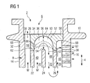
- the turbine blade 2 shown in fragmentary longitudinal section 4 comprises a longitudinally 4 between a (not visible here) blade root and a blade head 6 extending airfoil 8 with an end molded platform 10.
- the outer contour of the profiled airfoil 8 is characterized by a pressure side and a suction side wall 12 is formed.
- the two side walls run on the inflow side to a rounded front edge 14 and downstream to a flat rear edge 16 together.
- the turbine blade 2 For use in a gas turbine, in which the working medium flowing along the outside of the blade has temperatures of up to 1300 ° C. or more, the turbine blade 2 is designed to be coolable.
- the turbine blade 2 forms a so-called hollow profile. That is, the two side walls of the airfoil 8 surround a number of acted upon by a cooling medium M cavities in the blade interior.
- a number of intermediate walls 22, 24, 26 are arranged in the blade interior, which extend from side wall to side wall and thus impart structural stability to the airfoil 8 in the manner of a honeycomb structure ,
- the inlet of the coolant M here cooling air, via (not shown here) inlet openings in the blade root.
- the coolant M After the coolant M has flowed through the partly meandering in the blade interior coolant channels 18, 20, where it absorbs heat by predominantly convective heat transfer from the blade walls and removed, it leaves the turbine blade 2 via introduced into the blade wall outlet channels 28, 30, for example in Area of the trailing edge 16, and about so-called film cooling holes (not shown here).
- film cooling holes not shown here.
- the coolant M emerging from the film cooling holes is still considerable cooler than the working fluid flowing around the turbine blade 2, so that a coolant film protecting the blade surface from direct contact with the hot working medium can be formed.
- the turbine blade 2 comprises, for a simplified manufacturing process, two independently manufactured and subsequently interconnected components, namely a paddle main body 32 produced by the investment casting process, which, in addition to the side walls of the airfoil 8 and the inner partitions 22, 24, 26, also integrates with the airfoil 8 head-end platform 10 and the foot-side platform with a hook base (not shown) for attachment in the turbine and a arranged in the region of the blade head 6 closing element 34.
- the partially enclosed by the blade main body 32 cavity through the intermediate walls 22, 24, 26 in different Subspaces is divided, has a comparatively simple internal geometry with substantially rectilinear contours. Thus, the cost of creating the associated mold is kept very low.
- the support of the so-called core elements, which are in the mold during the casting instead of the later cavities, is facilitated because the head-side terminating element 34 is not mitgegossen with the'relichen blade body 32 and therefore the head portion of the blade main body 32 more accessible is.
- the closing element 34 seals the system of the coolant channels 18, 20 toward the blade head 6 outward and at the same time forms the outer boundary of a Umlenkpassage 36 for flowing through the coolant passage 20 coolant M.
- the turbine blade 2 has two coolant side parallel coolant channels 18, 20, which are fed via each arranged in the blade root inlet openings.
- the first coolant channel 18 supplies, in the region of the front edge 14, coolant holes, not shown here, so-called showerhead bores Cooling air.
- the remaining, not previously branched off to supply the showerhead holes cooling air exits through an introduced into the final element 34 outlet channel 28 and cools the Schaufelkopfregion.
- a second coolant channel 20 meanders through the blade interior.
- the coolant M first flows through a longitudinal section 40 formed by a first subspace in the direction of flow indicated by flow arrows 42 from the blade root to the blade head 6, is then deflected by 180 ° in the deflection passage 36 in the area of the blade head 6 and then exits in a second, formed by a second sub-space and from the blade head 6 to the blade root flow-through longitudinal portion 44 a.
- the first longitudinal section 40 of the meander-shaped coolant channel 20 is separated by the intermediate wall 22 from the adjacent to the leading edge 14 of the airfoil 8 coolant channel 18 and through the intermediate wall 24 from the second longitudinal section 44.
- the coolant M is again deflected by 180 ° and finally enters a again flowed from the blade root to the blade head 6 third longitudinal section 46, which in turn is separated by the intermediate wall 26 from the second longitudinal section 44.
- the coolant exits the turbine blade 2 and then mixes with the flowing through the flow channel of the gas turbine working fluid.
- the closing element 34 In order to form the deflection passage 36 connected on the coolant side between the first longitudinal section 40 and the second longitudinal section 44 of the coolant channel 20, the closing element 34 has a vault-like recess 50 on its underside facing the hollow profile.
- the coolant flow follows the contour of the deflection surface 52, which is essentially semicircular in longitudinal section, and therefore becomes - over the end edge 54 of the intermediate wall 24 across - deflected comparatively effective and without significant pressure loss by 180 °.
- the tailor-made in the end of the blade main body 32 at the head end of the Schobinenschaufel 2 used final element 34 has a bridge-like shape with the Umlenkpassage 36 defining main arc 56 and two laterally projecting arms 58.
- the closing element 34 is on corresponding Protrusions 60 of the blade main body 32; the two "bridge piers" (ie the webs 62) are supported without gaps on the intermediate walls 22 and 26.
- the closing element 34 is welded or soldered into its seat in the blade main body 32, wherein the coolant channels 18, 20 are sealed against each other and towards the outside.
- the distance a between the end edge 54 of the intermediate wall 24 and the vertex 64 of the arc 56 defines the free flow cross-section in the Umlenkpassage 36.
- a throttle point for the cooling air mass flow can be realized.
- only the end element 34 has to be adapted; an adjustment of the blade main body 32 is not required. This allows a rapid and cost-effective correction of the cooling air flow rate already in the development phase of the turbine blade 2 or later due to operating experience or with changed cooling requirements.
- FIG. 1 also apply in principle to the variant illustrated in FIG. 2, in which, however, the closing element 34 is further displaced toward the head end of the turbine blade 2 than in the variant according to FIG. 1 and thus completely outside the actual blade leaf 8 lies. Accordingly, the effective as a support end edges of the intermediate walls 22,26 continue to the head end of the turbine blade 2 out led out as in the embodiment in Figure 1, while the "bridge pillars" of the closing element 34 are made shortened.
Landscapes
- Engineering & Computer Science (AREA)
- Mechanical Engineering (AREA)
- General Engineering & Computer Science (AREA)
- Architecture (AREA)
- Turbine Rotor Nozzle Sealing (AREA)
Priority Applications (1)
| Application Number | Priority Date | Filing Date | Title |
|---|---|---|---|
| EP06007331A EP1843007A1 (fr) | 2006-04-06 | 2006-04-06 | Aube de turbine avec élément de fermeture séparé |
Applications Claiming Priority (1)
| Application Number | Priority Date | Filing Date | Title |
|---|---|---|---|
| EP06007331A EP1843007A1 (fr) | 2006-04-06 | 2006-04-06 | Aube de turbine avec élément de fermeture séparé |
Publications (1)
| Publication Number | Publication Date |
|---|---|
| EP1843007A1 true EP1843007A1 (fr) | 2007-10-10 |
Family
ID=36809168
Family Applications (1)
| Application Number | Title | Priority Date | Filing Date |
|---|---|---|---|
| EP06007331A Withdrawn EP1843007A1 (fr) | 2006-04-06 | 2006-04-06 | Aube de turbine avec élément de fermeture séparé |
Country Status (1)
| Country | Link |
|---|---|
| EP (1) | EP1843007A1 (fr) |
Cited By (2)
| Publication number | Priority date | Publication date | Assignee | Title |
|---|---|---|---|---|
| EP2990599A1 (fr) * | 2014-08-27 | 2016-03-02 | Siemens Aktiengesellschaft | Aube de turbine et turbine |
| EP4653667A3 (fr) * | 2019-05-22 | 2026-02-25 | Siemens Energy Global GmbH & Co. KG | Procédé pour effectuer des mesures de service sur une installation de conversion d'énergie et installation de conversion d'énergie |
Citations (8)
| Publication number | Priority date | Publication date | Assignee | Title |
|---|---|---|---|---|
| US2920865A (en) * | 1952-10-31 | 1960-01-12 | Rolls Royce | Bladed stator or rotor constructions with means to supply a fluid internally of the blades |
| US3628885A (en) * | 1969-10-01 | 1971-12-21 | Gen Electric | Fluid-cooled airfoil |
| US4650399A (en) * | 1982-06-14 | 1987-03-17 | United Technologies Corporation | Rotor blade for a rotary machine |
| US5624231A (en) * | 1993-12-28 | 1997-04-29 | Kabushiki Kaisha Toshiba | Cooled turbine blade for a gas turbine |
| EP1099825A1 (fr) * | 1999-11-12 | 2001-05-16 | Siemens Aktiengesellschaft | Aube de turbine et sa méthode de production |
| EP1101901A1 (fr) * | 1999-11-16 | 2001-05-23 | Siemens Aktiengesellschaft | Aube de turbine et sa méthode de production |
| DE10215375A1 (de) * | 2002-04-08 | 2003-10-16 | Siemens Ag | Turbinenlaufschaufel |
| DE102004011151A1 (de) * | 2003-03-19 | 2004-09-30 | Alstom Technology Ltd | Turbinenschaufel |
-
2006
- 2006-04-06 EP EP06007331A patent/EP1843007A1/fr not_active Withdrawn
Patent Citations (8)
| Publication number | Priority date | Publication date | Assignee | Title |
|---|---|---|---|---|
| US2920865A (en) * | 1952-10-31 | 1960-01-12 | Rolls Royce | Bladed stator or rotor constructions with means to supply a fluid internally of the blades |
| US3628885A (en) * | 1969-10-01 | 1971-12-21 | Gen Electric | Fluid-cooled airfoil |
| US4650399A (en) * | 1982-06-14 | 1987-03-17 | United Technologies Corporation | Rotor blade for a rotary machine |
| US5624231A (en) * | 1993-12-28 | 1997-04-29 | Kabushiki Kaisha Toshiba | Cooled turbine blade for a gas turbine |
| EP1099825A1 (fr) * | 1999-11-12 | 2001-05-16 | Siemens Aktiengesellschaft | Aube de turbine et sa méthode de production |
| EP1101901A1 (fr) * | 1999-11-16 | 2001-05-23 | Siemens Aktiengesellschaft | Aube de turbine et sa méthode de production |
| DE10215375A1 (de) * | 2002-04-08 | 2003-10-16 | Siemens Ag | Turbinenlaufschaufel |
| DE102004011151A1 (de) * | 2003-03-19 | 2004-09-30 | Alstom Technology Ltd | Turbinenschaufel |
Cited By (2)
| Publication number | Priority date | Publication date | Assignee | Title |
|---|---|---|---|---|
| EP2990599A1 (fr) * | 2014-08-27 | 2016-03-02 | Siemens Aktiengesellschaft | Aube de turbine et turbine |
| EP4653667A3 (fr) * | 2019-05-22 | 2026-02-25 | Siemens Energy Global GmbH & Co. KG | Procédé pour effectuer des mesures de service sur une installation de conversion d'énergie et installation de conversion d'énergie |
Similar Documents
| Publication | Publication Date | Title |
|---|---|---|
| EP1155760B1 (fr) | Procédé de fabrication d'une pièce moulée à charge thermique élevée | |
| EP1682342B1 (fr) | Systeme stratifie pour dissipation de chaleur a haute temperature et methode de fabrication | |
| EP3191244B1 (fr) | Procédé de production d'une aube mobile et aube obtenue | |
| WO2016058900A1 (fr) | Aube de turbine munie d'un module interne et procédé de fabrication d'une aube de turbine | |
| DE102011057071A1 (de) | Schaufelblattkomponente einer Turbomaschine und Kühlverfahren für diese | |
| DE102014109182A1 (de) | Turbinenkomponente und Verfahren zur Herstellung derselben | |
| EP1247602B1 (fr) | Procédé pour la fabrication d'une aube de turbine | |
| EP2101938B1 (fr) | Procédé de fabrication d'un modèle pour la reproduction par la technique de la coulée fine d'un composant qui présente au moins un espace creux | |
| DE102013109149A1 (de) | Turbinenschaufel und Herstellungsverfahren für eine solche | |
| EP2002085B1 (fr) | Segment d'aubes fixes d'une turbomachine thermique, procédé de fabrication associé et turbomachine thermique | |
| EP1331361B1 (fr) | Aube statorique de turbine coulée ayant un crochet de fixation | |
| EP0973998B1 (fr) | Procede pour refroidir une aube de turbine | |
| EP1481747A2 (fr) | Procédé de fabrication d'une pièce chargée par chaleur et piéce | |
| EP1843007A1 (fr) | Aube de turbine avec élément de fermeture séparé | |
| EP1661640A1 (fr) | Fabrication d'un modèle perdu et noyaux incorporé dans le modèle | |
| EP3514333B1 (fr) | Carénage d'extrémité d'aube de rotor pour une turbomachine, aube de rotor, procédé de fabrication d'un carénage d'extrémité d'aube de rotor et aube de rotor | |
| EP1674174B1 (fr) | Procédé de fabrication d'un moule de fonderie | |
| EP2095894A1 (fr) | Procédé destiné à la fabrication d'une aube de turbine refroidie à l'intérieur | |
| WO2019137757A1 (fr) | Pale d'aube de turbine, aube de turbine et procédé de fabrication associé | |
| EP2455586B1 (fr) | Rotor pour une turbomachine comportant des éléments d'étanchéité et des amortissements | |
| EP1662090B1 (fr) | Aube d'une turbine à gaz | |
| EP3231995A1 (fr) | Aube de turbine comprenant des pales de turbine et une enveloppe de pale | |
| EP3351735B1 (fr) | Élément de carter de turbomachine | |
| EP2031302A1 (fr) | Turbine à gaz comprenant un composant refroidissable | |
| EP1249575A1 (fr) | Aube de turbine |
Legal Events
| Date | Code | Title | Description |
|---|---|---|---|
| PUAI | Public reference made under article 153(3) epc to a published international application that has entered the european phase |
Free format text: ORIGINAL CODE: 0009012 |
|
| AK | Designated contracting states |
Kind code of ref document: A1 Designated state(s): AT BE BG CH CY CZ DE DK EE ES FI FR GB GR HU IE IS IT LI LT LU LV MC NL PL PT RO SE SI SK TR |
|
| AX | Request for extension of the european patent |
Extension state: AL BA HR MK YU |
|
| AKX | Designation fees paid | ||
| STAA | Information on the status of an ep patent application or granted ep patent |
Free format text: STATUS: THE APPLICATION IS DEEMED TO BE WITHDRAWN |
|
| 18D | Application deemed to be withdrawn |
Effective date: 20080411 |
|
| REG | Reference to a national code |
Ref country code: DE Ref legal event code: 8566 |