EP1843128A2 - Kreuzlinienlaser - Google Patents
Kreuzlinienlaser Download PDFInfo
- Publication number
- EP1843128A2 EP1843128A2 EP07090065A EP07090065A EP1843128A2 EP 1843128 A2 EP1843128 A2 EP 1843128A2 EP 07090065 A EP07090065 A EP 07090065A EP 07090065 A EP07090065 A EP 07090065A EP 1843128 A2 EP1843128 A2 EP 1843128A2
- Authority
- EP
- European Patent Office
- Prior art keywords
- main body
- body housing
- swingable
- regulating
- laser light
- Prior art date
- Legal status (The legal status is an assumption and is not a legal conclusion. Google has not performed a legal analysis and makes no representation as to the accuracy of the status listed.)
- Withdrawn
Links
- 230000001105 regulatory effect Effects 0.000 claims abstract description 76
- 230000001678 irradiating effect Effects 0.000 claims abstract description 24
- 239000011358 absorbing material Substances 0.000 claims abstract description 20
- 239000000463 material Substances 0.000 claims description 17
- 238000013016 damping Methods 0.000 claims description 14
- 230000003287 optical effect Effects 0.000 claims description 13
- 238000010276 construction Methods 0.000 description 19
- NJPPVKZQTLUDBO-UHFFFAOYSA-N novaluron Chemical compound C1=C(Cl)C(OC(F)(F)C(OC(F)(F)F)F)=CC=C1NC(=O)NC(=O)C1=C(F)C=CC=C1F NJPPVKZQTLUDBO-UHFFFAOYSA-N 0.000 description 4
- 244000043261 Hevea brasiliensis Species 0.000 description 3
- 229920003052 natural elastomer Polymers 0.000 description 3
- 229920001194 natural rubber Polymers 0.000 description 3
- 230000002093 peripheral effect Effects 0.000 description 3
- 229920002635 polyurethane Polymers 0.000 description 3
- 239000004814 polyurethane Substances 0.000 description 3
- 229920002379 silicone rubber Polymers 0.000 description 3
- 238000010521 absorption reaction Methods 0.000 description 1
- 230000001419 dependent effect Effects 0.000 description 1
- 230000001747 exhibiting effect Effects 0.000 description 1
- 230000004048 modification Effects 0.000 description 1
- 238000012986 modification Methods 0.000 description 1
- 230000010355 oscillation Effects 0.000 description 1
Images




Classifications
-
- G—PHYSICS
- G01—MEASURING; TESTING
- G01C—MEASURING DISTANCES, LEVELS OR BEARINGS; SURVEYING; NAVIGATION; GYROSCOPIC INSTRUMENTS; PHOTOGRAMMETRY OR VIDEOGRAMMETRY
- G01C15/00—Surveying instruments or accessories not provided for in groups G01C1/00 - G01C13/00
- G01C15/002—Active optical surveying means
- G01C15/004—Reference lines, planes or sectors
Definitions
- the present invention relates to a cross line laser, which draws perpendicular lines or horizontal lines by irradiating a laser beam to a target to be irradiated such as a wall, a ceiling and a floor etc. at a building site etc. More particularly, the invention relates to a cross line laser which can protect members, for instance, a laser source unit etc. installed to a swingably disposed swingable member, which is installed within an outer covering member of the cross line laser, from various impacts.
- this kind of cross line laser includes an swingable member swingably installed in a suspended manner via a gimbal mechanism within the main body housing, to which a laser light generation means for irradiating a laser beam in a predetermined direction, and a laser source unit having an optical means for irradiating the laser beam generated by the laser light generation means in the predetermined direction are installed.
- a conventional cross line laser is constructed such that a fixing plate for installing the gimbal mechanism and a supporting plate for supporting the fixing plate are fixed to each other via an impact absorbing material, and the impact absorbing material is placed at an area where a lower free end of the swingable member.
- An example of this type of configuration is disclosed in Japanese Laid Open Patent Publication No. 2005-292059 .
- the impact absorbing materials (utilized for fixing the fixing plate and the supporting plate) have a bush construction that is fitted with a bolt used for connecting these plates.
- the impact absorbing materials for absorbing impacts generated by the contact of the lower free end of the swingable member has a construction simply utilizing an O-ring.
- these impact absorbing materials can serve to absorb impacts, the level of absorption of an impact is not suitable for various configuration. Therefore it is an object of the present invention to provide a cross line laser that can effectively protect laser source units etc. installed to a swingably disposed swingable member from various kinds of vibrations and impacts.
- One aspect according to the present invention includes a cross line laser having a main body housing having a plurality of windows for irradiating a laser light in vertical and horizontal directions therethrough; a swingable member positioned within the main body housing and being able to swing via a gimbal mechanism; and a plurality of laser light source units connected to the swingable member and each including a laser light generating means and an optical means; characterized in that a regulating member including an impact absorbing material is disposed within the main body housing in a position opposite a lower free end of the swingable member; the lower free end of the swingable member positionable within the regulating member; a regulating opening is formed in the regulating member and defines a contact surface to which the lower free end of the swingable member is able to contact when the swingable member moves; and a plurality of cut-in grooves are formed in the contact surface and are spaced from each other at predetermined intervals.
- the lateral surface of the lower free end of the swingable member can contact the contact surface of the regulating opening of the regulating member made of impact absorbing material, and the vibrations and impacts generated by the contact can be effectively damped and absorbed due to the contacting surface having a plurality of cut-in grooves.
- each laser source unit installed to the swingable member is effectively protected from the vibrations and the impacts.
- the regulating member includes a plate-like member.
- the plate-like member has an increased thickness portion provided between the regulating opening and an outer periphery of the plate-like member. A space is formed through the increased thickness portion.
- the lateral surface of the lower free end of the swingable member can contact the contact surface of the regulating opening of the regulating member made of the impact absorbing material, and the vibrations and impacts generated by the contact can be more effectively (efficiently) damped and absorbed by the space formed in the regulating member.
- each laser source unit installed to the swingable member is effectively protected from the vibrations and the impacts.
- the regulating member in another embodiment, includes a plate-like member having a substantially circular or rectangular configuration.
- the regulating opening has a circular configuration and is formed in a central portion of the regulating member.
- the plate-like member has an increased thickness portion provided between the regulating opening and an outer periphery of the plate-like member. A substantially elliptical or triangular space is formed through the increased thickness portion.
- the lateral surface of the lower free end of the swingable member can contact the contact surface of the regulating opening of the regulating member made of the impact absorbing material, and the vibrations and impacts generated by the contact can be more effectively (efficiently) damped and absorbed by the space formed in the regulating member.
- each laser source unit installed to the swingable member is effectively protected from the vibrations and the impacts.
- a cross line laser having a main body housing having a plurality of)open windows for irradiating a laser light in vertical and horizontal directions therethrough; a swingable member disposed in a suspended manner within the main body housing and being able to swing via a gimbal mechanism; and a plurality of laser light source units connected to the swingable member and including a laser light generating means and an optical means; characterized in that a supporting member supporting the gimbal mechanism is connected to an attaching member in a lapped manner, the attaching member being installed inside of the main body housing, the attaching member and the supporting member are connected to each other by a rivet-like jointing member, a space is provided between the contacting surfaces of the attaching member and the supporting member, and the rivet-like jointing member is made of a vibration damping material.
- the rivet-like jointing member made of vibrations damping material at a connecting region between the attaching member and the supporting member can damp and absorb the vibrations and the impacts transmitted from the main body housing to the swingable member, and the assembling construction at the connecting region can be simplified.
- each laser source unit installed to the swingable member is effectively protected from the vibrations and the impacts.
- the jointing member includes a shaft-like member.
- the shaft-like member has head portions and a flange portion that are formed integrally with a shaft of the shaft-like member.
- the head portions have a larger diameter than the shaft diameter and are disposed on opposite ends of the shaft.
- the flange portion has a larger diameter than the shaft and is disposed on a substantially middle portion of the shaft.
- each laser source unit installed to the swingable member is effectively protected from the vibrations and the impacts.
- a cross line laser having a main body housing having an open windows for irradiating a laser light in vertical and horizontal directions therethrough; a swingable member disposed in a suspended manner within the main body housing and being able to swing via a gimbals mechanism; and a laser light source units installed at a predetermined position of the swingable member and each including a laser light generating means and an optical means; characterized in that the open windows for irradiating the laser beam is formed in at least one outer upright surface of the main body housing; a portion of an outer upright surface of the main body housing is formed as a display surface for displaying a laser beam irradiation state; and an outer covering member made of an impact damping material is positioned so that it surrounds other outer periphery surfaces and a portion of a bottom surface of the main body housing except for the at least one outer periphery surface and the display surface.
- each laser source unit installed to the swingable member is effectively protected from the vibrations and the impacts.
- the outer covering member has a plurality of linear spaces with a predetermined depth and width formed in an inner surface of the covering member contacting the main body housing.
- each laser source unit installed to the swingable member is effectively protected from the vibrations and the impacts.
- the outer covering member has a plurality of substantially hemispherical projections formed at desired intervals on the at least one outer upright surface.
- each laser source unit installed to the swingable member is effectively protected from the vibrations and the impacts.
- a cross line laser having a main body housing having an open windows for irradiating a laser light in vertical and horizontal directions therethrough; a swingable member disposed in a suspended manner within the main body housing and being able to swing via a gimbal mechanism; and a laser light source units installed at a predetermined position of the swingable member and each including a laser light generating means and an optical means; characterized in that a supporting member supporting the gimbal mechanism is assembled with an attaching member in a lapped manner, the attaching member being installed inside of the main body housing; the attaching member and the supporting member are connected to each other by a rivet-like jointing member made of vibration damping material in such a manner that a predetermined space is provided between the contacting surfaces of the attaching member and the supporting member; a regulating member comprising an impact absorbing material is disposed within the main body housing in a position opposing to a lower free end of the swingable member; the lower free end of the swingable member is positionable into
- each laser source unit installed to the swingable member is effectively protected from the vibrations and the impacts.
- a cross line laser having a main body housing having an open windows for irradiating a laser light in vertical and horizontal directions therethrough; a swingable member disposed in a suspended manner within the main body housing and being able to swing via a gimbal mechanism; and a laser light source units installed at a predetermined position of the swingable member and each including a laser light generating means and an optical means; characterized in that: a supporting member supporting the gimbal mechanism is assembled with an attaching member, the attaching member positioned inside the main body housing; the attaching member and the supporting member are connected to each other by a rivet-like jointing member made of vibration damping material such that a space is provided between the contacting surfaces of the attaching member and the supporting member; a regulating member comprising an impact absorbing material is positioned within the main body housing opposite a lower free end of the swingable member; the lower free end of the swingable member insertable into the regulating member; a regulating opening is formed in the regulating member and defines
- each laser source unit installed to the swingable member is effectively protected from the vibrations and the impacts.
- FIGS. 1 to 10 An embodiment according to the present invention will now be described with reference to FIGS. 1 to 10.
- a cross line laser 1 is constituted primarily by an swingable member 2, an apparatus main body 4 including a plural number of the laser light source units 3, which are installed to the swingable member 2, a main body housing 5 in which the apparatus main body 4 is installed, and an outer covering member 6, which is attached in such a manner that it covers the outer periphery and the lower portion of the main body housing 5.
- the main body housing 5 is formed to have a tubular configuration with a substantially elliptical cross-section, an outer upright surface 5a, which is a part of the outer periphery of the main body housing 5 and defines a curved surface that becomes gradually narrower from a position at a substantially central lower portion towards the upper surface.
- a first open window 7 for irradiating a laser beam, which will be described later, as a vertical linear beam, and a second open window 8 positioned on the lower side of the first open window 7 for irradiating the laser beam, which will be described later, as a horizontal linear beam, are formed through the curved outer upright surface 5a.
- the upper surface of the main body housing 5 defines a display surface 5b for exhibiting various display lamps and instruction marks on the surface for displaying irradiation conditions and the like of the laser beam which will be described later.
- a display surface 5b for exhibiting various display lamps and instruction marks on the surface for displaying irradiation conditions and the like of the laser beam which will be described later.
- one outer upright surface 5a is formed and the first open window 7 and the second open window 8 are formed therethrough, however, plural number of outer upright surfaces can be formed.
- a plate-like pedestal member 9 is positioned and a supporting column member 10 is integrally installed in an upright manner on a portion of the outer periphery of the pedestal member 9.
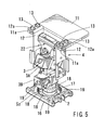
- an attaching member 11 horizontally extends therefrom, a pair of left and right inverted-L shaped supporting members 12 are connected in a suspended manner on both lateral edges of one end of the attaching member 11 and the swingable member 2 is installed in a suspended manner, and thus able to swing via a gimbal mechanism 22 assembled between the pair of supporting members 12.
- FIG. 8 and FIG 9 At the top end of the supporting column member 10, an attaching member 11 horizontally extends therefrom, a pair of left and right inverted-L shaped supporting members 12 are connected in a suspended manner on both lateral edges of one end of the attaching member 11 and the swingable member 2 is installed in a suspended manner, and thus able to swing via a gimbal mechanism 22 assembled between the pair of supporting members 12.
- FIG. 5 shows the state where the pair of supporting members 12 is connected in a suspended manner to projecting pieces 11a from the inside thereof, which are formed on both lateral edges of one end of the attaching member 11, the attaching construction of the supporting members 12 to the attaching member 11 can be achieved by any other constructions.
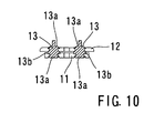
- the attaching (joining) construction of the supporting members 12 to the attaching member 11 As shown in FIG. 7 and FIG. 10, as the attaching (joining) construction of the supporting members 12 to the attaching member 11, upper curved pieces 12a of the supporting members 12 are positioned on the upper surface of the attaching member 11, and both members are coupled to each other via rivet-like jointing members 13 made of vibrations damping material respectively at two sites.
- the jointing members 13 are preferably molded with materials such as natural rubber, silicon rubber, and polyurethane etc., which have good performance in absorbing vibrations and impacts energy, as the vibrations damping material.
- each jointing members 13 can be formed in a shaft like configuration and each integrally formed with a head portion 13a with a larger diameter than the shaft diameter and formed on opposite ends of the shaft.
- Each can include a flange portion 13b with a larger diameter than the shaft diameter and formed on a substantially middle portion of the shaft.
- the shaft can be fitted in a press fitting condition into holes of the attaching member 11 and each supporting member 12, and the connection be made, while both head portions 13a are respectively positioned on the side of the upper surface of the attaching member 11 and on the side of the lower surface of the supporting member 12.
- the flange part 13b can be placed such that a predetermined gap S1 is provided between the contacting surfaces of the attaching member 11 and the supporting member 12.
- each jointing member 13 (for example, in a rivet-like configuration) can absorb and/or damp vibrations and impacts transmitted from the attaching member 11 to the supporting member 12.
- a first the laser light source units 3A having a laser light generating means 14a and an optical means 15a (which can be a cylindrical lens irradiating the laser light generated by the laser light generating means 14a in a predetermined vertical direction).
- swingable member 2 can connected to a second the laser light source units 3B having a laser light generating means 14b and an optical means 15b which is a cylindrical lens irradiating the lager light generated by the laser generating means 14b in a predetermined horizontal direction.
- Both laser light source 3A and 3B can be installed with a phase difference with respect to upward and downward directions such that these units correspond to the first opening window 7 and the second opening window 8.
- swingable member 2 is able to accommodate a construction that enables irradiation of the laser light in an up and down direction.
- a recessed portion with a pre-determined depth is formed, in the upper surface of the pedestal member 9 and define a pair of convex portions 9a on opposite sides of the recessed portion and a regulating member 16 is fitted between the convex portions 9a.
- the regulating member 16 can be formed of an impact absorbing material and shaped in a rectangular plate-like body with a desired thickness.
- the regulating member 16 can also include a circular shaped regulating opening 17 formed in the center portion of the regulating member 16 and extending therethrough, and a number of cut-in grooves 18 formed in the axial direction of the regulating opening 17 at predetermined intervals therebetween (the intervals are uniform in the drawings) in the contacting surface of the inner periphery of the regulating opening 17. Further, substantially triangularly shaped openings 19 can be formed through increased thickness portions formed at corners of the regulating member 16 between the regulating opening 17 and the outer peripheral edge.
- the regulating member 16 is preferably molded with materials such as natural rubber, silicon rubber, and polyurethane etc., which have good performance in absorbing oscillation and impact energy.
- the lower free end of the swingable member 2 is positioned within the regulating opening 17 of the regulating member 16 so as to extend within space SZ, and when the swingable member 2 swings more than necessary, the lateral surface of the lower free end of the swingable member 2 can contact the regulating member 16. Therefore, when the swingable member 2 swings more than necessary, the lateral surface of its lower free end contacts the circumference of the regulating opening 17 of the regulating member 16, the vibrations and impacts generated by the contact is damped and/or absorbed by the contacting surface where a number cut-in grooves 18 are formed.
- the regulating member 16 is formed to have a substantially rectangular configuration in the embodiment shown in the attached drawings, it can be formed in a circular configuration. In such as case, the openings 19 can be formed in a substantially elliptical configuration on the desired positions of the increased thickness portions between the regulating opening 17 and the outer peripheral edge.
- the lower open portion of the main body hosing 5 can be fitted with a stopped portion at the outer periphery of the pedestal member 9 such that the main body housing 5 covers the apparatus main part 4 from the outer side.
- the outer covering member 6 is molded with an impact absorbing material having a pre-determined thickness and is configured to conform to a three dimensional shape of the outer upright surface 5a and the display surface 5b of the upper surface of the main body housing 5.
- the outer covering member 6 is installed in such a manner that it surrounds (covers) the outer peripheral surface and the bottom surface of the main body housing 5 except for the outer upright surface 5a and the upper display surface 5b.
- the outer covering member 6 is desirably molded with material such as natural rubber, silicon rubber, and polyurethane etc., which has a good performance in absorbing vibrations and impacts energy.
- the outer covering member 6 is installed in such a manner that it surrounds (covers) the outer upright surfaces and the display surfaces 5b of the upper surface of the main body housing 5, and further, the other portions of the outer surface and the bottom surface except for a portion for irradiating the laser light in down and up directions.
- a number of linear spaces 20 with a pre-determined depth and a width can be formed in up-down directions, lateral (left and right) directions or in a rectangular pattern. Further, a number of substantially hemispherical projections 21 can be formed at desired intervals to extend from the outer upright surface of the outer covering member 6. Note that the liner spaces 20 are omitted in Fig. 2. Accordingly, when an impact has been applied from outside to the main body housing 5, in other words, the entire cross line laser 1, the outer covering member 6 can damp and/or absorb the impact.
- the present embodiment is constructed as explained above, when the swingable member 2 swings more than necessary, the lateral surface of the lower free end of the swingable member 2 contacts the periphery of the regulating opening 17 of the regulating member 16 made of the impact absorbing material, such that the contacting surface with a number of cut out grooves 18 formed in the periphery of the regulating opening 17 damps and/or absorbs the vibration and the impact from the contact.
- the regulating member 16 itself can damp and absorb the vibrations and the impacts, and it is possible to further effectively (efficiently) damp and/or absorb the vibrations and impacts.
- the rivet-like jointing member 13 made of vibrations damping material at a connecting region between the attaching member 11 and the supporting member 12 can damp and absorb the vibrations and the impacts transmitted from the main body housing 5 to the swingable member 2, and at the connecting region, no other jointing means such as bolts etc. are required, thereby simplifying the assembling construction.
Landscapes
- Physics & Mathematics (AREA)
- Engineering & Computer Science (AREA)
- General Physics & Mathematics (AREA)
- Radar, Positioning & Navigation (AREA)
- Remote Sensing (AREA)
- Laser Beam Processing (AREA)
- Mechanical Light Control Or Optical Switches (AREA)
- Vibration Dampers (AREA)
- Vibration Prevention Devices (AREA)
Applications Claiming Priority (1)
| Application Number | Priority Date | Filing Date | Title |
|---|---|---|---|
| JP2006101702A JP4920286B2 (ja) | 2006-04-03 | 2006-04-03 | レーザー墨出し器 |
Publications (2)
| Publication Number | Publication Date |
|---|---|
| EP1843128A2 true EP1843128A2 (de) | 2007-10-10 |
| EP1843128A3 EP1843128A3 (de) | 2007-12-19 |
Family
ID=38227794
Family Applications (1)
| Application Number | Title | Priority Date | Filing Date |
|---|---|---|---|
| EP07090065A Withdrawn EP1843128A3 (de) | 2006-04-03 | 2007-04-02 | Kreuzlinienlaser |
Country Status (3)
| Country | Link |
|---|---|
| EP (1) | EP1843128A3 (de) |
| JP (1) | JP4920286B2 (de) |
| CN (1) | CN101059341B (de) |
Cited By (5)
| Publication number | Priority date | Publication date | Assignee | Title |
|---|---|---|---|---|
| DE102008008846A1 (de) * | 2008-02-13 | 2009-09-17 | Robert Bosch Gmbh | Messwerkzeug |
| US10466049B2 (en) | 2015-10-13 | 2019-11-05 | Stanley Black & Decker Inc. | Laser level |
| DE102018213739A1 (de) * | 2018-08-15 | 2020-02-20 | Deutsches Zentrum für Luft- und Raumfahrt e.V. | System zur Positionierung und Nivellierung |
| US11287258B2 (en) | 2019-01-16 | 2022-03-29 | Milwaukee Electric Tool Corporation | Laser projection tools and mounting accessories |
| US11385055B2 (en) | 2019-07-23 | 2022-07-12 | Milwaukee Electric Tool Corporation | Laser emitter with a modular storage unit |
Families Citing this family (2)
| Publication number | Priority date | Publication date | Assignee | Title |
|---|---|---|---|---|
| DE202006014576U1 (de) * | 2006-08-21 | 2008-01-03 | STABILA Messgeräte Gustav Ullrich GmbH | Schutzeinrichtung |
| DE102014218185B4 (de) * | 2014-09-11 | 2019-06-19 | Robert Bosch Gmbh | Verfahren zur Montierung einer Pendellaservorrichtung |
Family Cites Families (11)
| Publication number | Priority date | Publication date | Assignee | Title |
|---|---|---|---|---|
| JPS59137432A (ja) * | 1983-01-25 | 1984-08-07 | Mitsubishi Petrochem Co Ltd | アルキルフエノ−ル類の製造法 |
| DE19757532A1 (de) * | 1997-12-23 | 1999-06-24 | Hilti Ag | Baulaser |
| DE19810447A1 (de) * | 1998-03-11 | 1999-09-16 | Hilti Ag | Aufhängung für eine schwerkraftbeeinflusste Messeinrichtung |
| JP3597114B2 (ja) * | 2000-05-12 | 2004-12-02 | 株式会社オーディオテクニカ | レーザー墨出し器における耐衝撃構造 |
| JP2002071350A (ja) * | 2000-09-01 | 2002-03-08 | Hitachi Koki Co Ltd | レーザー墨出し器 |
| US6848188B2 (en) * | 2001-08-10 | 2005-02-01 | Toolz, Ltd. | Laser alignment device providing multiple references |
| JP3838168B2 (ja) * | 2002-06-25 | 2006-10-25 | 松下電工株式会社 | レーザー墨出し器 |
| US6938350B1 (en) * | 2002-12-31 | 2005-09-06 | PLS—Pacific Laser Systems | Apparatus for producing a reference plane |
| JP4195988B2 (ja) * | 2003-05-26 | 2008-12-17 | パナソニック電工株式会社 | 水準器 |
| US7134211B2 (en) * | 2004-03-18 | 2006-11-14 | Black & Decker Inc. | Laser level |
| JP2005292059A (ja) * | 2004-04-02 | 2005-10-20 | Hitachi Koki Co Ltd | レーザ墨出し装置 |
-
2006
- 2006-04-03 JP JP2006101702A patent/JP4920286B2/ja not_active Expired - Fee Related
-
2007
- 2007-04-02 EP EP07090065A patent/EP1843128A3/de not_active Withdrawn
- 2007-04-03 CN CN2007101053538A patent/CN101059341B/zh not_active Expired - Fee Related
Non-Patent Citations (1)
| Title |
|---|
| None |
Cited By (11)
| Publication number | Priority date | Publication date | Assignee | Title |
|---|---|---|---|---|
| DE102008008846A1 (de) * | 2008-02-13 | 2009-09-17 | Robert Bosch Gmbh | Messwerkzeug |
| US10466049B2 (en) | 2015-10-13 | 2019-11-05 | Stanley Black & Decker Inc. | Laser level |
| US11428529B2 (en) | 2015-10-13 | 2022-08-30 | Stanley Black & Decker Inc. | Laser level |
| US11859975B2 (en) | 2015-10-13 | 2024-01-02 | Stanley Black & Decker Inc. | Laser level |
| US12332055B2 (en) | 2015-10-13 | 2025-06-17 | Stanley Black & Decker, Inc. | Laser level |
| DE102018213739A1 (de) * | 2018-08-15 | 2020-02-20 | Deutsches Zentrum für Luft- und Raumfahrt e.V. | System zur Positionierung und Nivellierung |
| EP3613698A1 (de) | 2018-08-15 | 2020-02-26 | Deutsches Zentrum für Luft- und Raumfahrt e.V. | System zur positionierung und nivellierung |
| US11287258B2 (en) | 2019-01-16 | 2022-03-29 | Milwaukee Electric Tool Corporation | Laser projection tools and mounting accessories |
| US11781865B2 (en) | 2019-01-16 | 2023-10-10 | Milwaukee Electric Tool Corporation | Laser projection tools and mounting accessories |
| US11385055B2 (en) | 2019-07-23 | 2022-07-12 | Milwaukee Electric Tool Corporation | Laser emitter with a modular storage unit |
| US12092457B2 (en) | 2019-07-23 | 2024-09-17 | Milwaukee Electric Tool Corporation | Laser emitter with a modular storage unit |
Also Published As
| Publication number | Publication date |
|---|---|
| EP1843128A3 (de) | 2007-12-19 |
| JP2007278718A (ja) | 2007-10-25 |
| JP4920286B2 (ja) | 2012-04-18 |
| CN101059341A (zh) | 2007-10-24 |
| CN101059341B (zh) | 2012-09-12 |
Similar Documents
| Publication | Publication Date | Title |
|---|---|---|
| EP1843128A2 (de) | Kreuzlinienlaser | |
| JP2007140246A (ja) | 表示装置 | |
| JP2009138493A (ja) | 床支持具及び床構造 | |
| KR102143471B1 (ko) | 진동흡수 가능한 일체형 폴대 | |
| JP2016518287A (ja) | 自動車のフロントモジュールのバンパの支持構造 | |
| JP2019078103A (ja) | 遮音壁、最下層遮音パネル、及びベースプレート | |
| JP4197530B2 (ja) | レーザー墨出し器 | |
| JP5787743B2 (ja) | 可動式ホームゲート装置のセンサユニット | |
| JP2004192781A (ja) | 動吸振器、光ディスク装置および動吸振器の対応振動数決定方法 | |
| US7418786B2 (en) | Marking device | |
| KR102025618B1 (ko) | 방진 성능 및 열교차단 성능 그리고 구조적 강성을 개선한 경량 지붕구조 | |
| JP5128969B2 (ja) | 床支持吸振具、及び、床構造 | |
| KR101161785B1 (ko) | 내진성능을 갖는 일체형 창호시스템 | |
| KR102152607B1 (ko) | Led를 구비한 유지보수형 방음패널 | |
| CN100455795C (zh) | 具有噪声降低结构的密封型压缩机 | |
| JP4251398B2 (ja) | レーザー墨出し器 | |
| KR200226731Y1 (ko) | 반도체포토마스크보관케이스 | |
| JP4196120B2 (ja) | レーザー墨出し器 | |
| KR102229331B1 (ko) | 원터치 개폐형 투명방음패널 | |
| HK1108937A (en) | Cross line laser | |
| KR102231218B1 (ko) | 강성보강 가로등 | |
| JP4113828B2 (ja) | 制震壁構造 | |
| JP2005248600A (ja) | 防音壁及び防音壁の施工方法 | |
| KR102631513B1 (ko) | 소음방지수단이 구비된 사각맨홀 | |
| KR102356561B1 (ko) | 교체가 용이한 방음패널 구조체 |
Legal Events
| Date | Code | Title | Description |
|---|---|---|---|
| PUAI | Public reference made under article 153(3) epc to a published international application that has entered the european phase |
Free format text: ORIGINAL CODE: 0009012 |
|
| AK | Designated contracting states |
Kind code of ref document: A2 Designated state(s): AT BE BG CH CY CZ DE DK EE ES FI FR GB GR HU IE IS IT LI LT LU LV MC MT NL PL PT RO SE SI SK TR |
|
| AX | Request for extension of the european patent |
Extension state: AL BA HR MK YU |
|
| PUAL | Search report despatched |
Free format text: ORIGINAL CODE: 0009013 |
|
| AK | Designated contracting states |
Kind code of ref document: A3 Designated state(s): AT BE BG CH CY CZ DE DK EE ES FI FR GB GR HU IE IS IT LI LT LU LV MC MT NL PL PT RO SE SI SK TR |
|
| AX | Request for extension of the european patent |
Extension state: AL BA HR MK YU |
|
| 17P | Request for examination filed |
Effective date: 20080610 |
|
| 17Q | First examination report despatched |
Effective date: 20080721 |
|
| AKX | Designation fees paid |
Designated state(s): DE GB |
|
| GRAP | Despatch of communication of intention to grant a patent |
Free format text: ORIGINAL CODE: EPIDOSNIGR1 |
|
| STAA | Information on the status of an ep patent application or granted ep patent |
Free format text: STATUS: THE APPLICATION IS DEEMED TO BE WITHDRAWN |
|
| 18D | Application deemed to be withdrawn |
Effective date: 20111020 |