EP1843138A1 - Vis comportant une couche de matériau conducteur formant un capteur - Google Patents
Vis comportant une couche de matériau conducteur formant un capteur Download PDFInfo
- Publication number
- EP1843138A1 EP1843138A1 EP07105448A EP07105448A EP1843138A1 EP 1843138 A1 EP1843138 A1 EP 1843138A1 EP 07105448 A EP07105448 A EP 07105448A EP 07105448 A EP07105448 A EP 07105448A EP 1843138 A1 EP1843138 A1 EP 1843138A1
- Authority
- EP
- European Patent Office
- Prior art keywords
- layer
- object according
- sensing device
- electrically conducting
- conducting material
- Prior art date
- Legal status (The legal status is an assumption and is not a legal conclusion. Google has not performed a legal analysis and makes no representation as to the accuracy of the status listed.)
- Granted
Links
Images



Classifications
-
- G—PHYSICS
- G01—MEASURING; TESTING
- G01K—MEASURING TEMPERATURE; MEASURING QUANTITY OF HEAT; THERMALLY-SENSITIVE ELEMENTS NOT OTHERWISE PROVIDED FOR
- G01K1/00—Details of thermometers not specially adapted for particular types of thermometer
- G01K1/14—Supports; Fastening devices; Arrangements for mounting thermometers in particular locations
-
- G—PHYSICS
- G01—MEASURING; TESTING
- G01D—MEASURING NOT SPECIALLY ADAPTED FOR A SPECIFIC VARIABLE; ARRANGEMENTS FOR MEASURING TWO OR MORE VARIABLES NOT COVERED IN A SINGLE OTHER SUBCLASS; TARIFF METERING APPARATUS; MEASURING OR TESTING NOT OTHERWISE PROVIDED FOR
- G01D11/00—Component parts of measuring arrangements not specially adapted for a specific variable
- G01D11/24—Housings ; Casings for instruments
- G01D11/245—Housings for sensors
-
- G—PHYSICS
- G01—MEASURING; TESTING
- G01D—MEASURING NOT SPECIALLY ADAPTED FOR A SPECIFIC VARIABLE; ARRANGEMENTS FOR MEASURING TWO OR MORE VARIABLES NOT COVERED IN A SINGLE OTHER SUBCLASS; TARIFF METERING APPARATUS; MEASURING OR TESTING NOT OTHERWISE PROVIDED FOR
- G01D11/00—Component parts of measuring arrangements not specially adapted for a specific variable
- G01D11/30—Supports specially adapted for an instrument; Supports specially adapted for a set of instruments
-
- G—PHYSICS
- G01—MEASURING; TESTING
- G01K—MEASURING TEMPERATURE; MEASURING QUANTITY OF HEAT; THERMALLY-SENSITIVE ELEMENTS NOT OTHERWISE PROVIDED FOR
- G01K7/00—Measuring temperature based on the use of electric or magnetic elements directly sensitive to heat ; Power supply therefor, e.g. using thermoelectric elements
- G01K7/02—Measuring temperature based on the use of electric or magnetic elements directly sensitive to heat ; Power supply therefor, e.g. using thermoelectric elements using thermoelectric elements, e.g. thermocouples
-
- G—PHYSICS
- G01—MEASURING; TESTING
- G01L—MEASURING FORCE, STRESS, TORQUE, WORK, MECHANICAL POWER, MECHANICAL EFFICIENCY, OR FLUID PRESSURE
- G01L1/00—Measuring force or stress, in general
- G01L1/20—Measuring force or stress, in general by measuring variations in ohmic resistance of solid materials or of electrically-conductive fluids; by making use of electrokinetic cells, i.e. liquid-containing cells wherein an electrical potential is produced or varied upon the application of stress
- G01L1/22—Measuring force or stress, in general by measuring variations in ohmic resistance of solid materials or of electrically-conductive fluids; by making use of electrokinetic cells, i.e. liquid-containing cells wherein an electrical potential is produced or varied upon the application of stress using resistance strain gauges
-
- G—PHYSICS
- G01—MEASURING; TESTING
- G01L—MEASURING FORCE, STRESS, TORQUE, WORK, MECHANICAL POWER, MECHANICAL EFFICIENCY, OR FLUID PRESSURE
- G01L1/00—Measuring force or stress, in general
- G01L1/20—Measuring force or stress, in general by measuring variations in ohmic resistance of solid materials or of electrically-conductive fluids; by making use of electrokinetic cells, i.e. liquid-containing cells wherein an electrical potential is produced or varied upon the application of stress
- G01L1/22—Measuring force or stress, in general by measuring variations in ohmic resistance of solid materials or of electrically-conductive fluids; by making use of electrokinetic cells, i.e. liquid-containing cells wherein an electrical potential is produced or varied upon the application of stress using resistance strain gauges
- G01L1/2206—Special supports with preselected places to mount the resistance strain gauges; Mounting of supports
- G01L1/2231—Special supports with preselected places to mount the resistance strain gauges; Mounting of supports the supports being disc- or ring-shaped, adapted for measuring a force along a single direction
-
- G—PHYSICS
- G01—MEASURING; TESTING
- G01L—MEASURING FORCE, STRESS, TORQUE, WORK, MECHANICAL POWER, MECHANICAL EFFICIENCY, OR FLUID PRESSURE
- G01L5/00—Apparatus for, or methods of, measuring force, work, mechanical power, or torque, specially adapted for specific purposes
- G01L5/0004—Force transducers adapted for mounting in a bore of the force receiving structure
-
- G—PHYSICS
- G01—MEASURING; TESTING
- G01L—MEASURING FORCE, STRESS, TORQUE, WORK, MECHANICAL POWER, MECHANICAL EFFICIENCY, OR FLUID PRESSURE
- G01L9/00—Measuring steady of quasi-steady pressure of fluid or fluent solid material by electric or magnetic pressure-sensitive elements; Transmitting or indicating the displacement of mechanical pressure-sensitive elements, used to measure the steady or quasi-steady pressure of a fluid or fluent solid material, by electric or magnetic means
- G01L9/0041—Transmitting or indicating the displacement of flexible diaphragms
- G01L9/0072—Transmitting or indicating the displacement of flexible diaphragms using variations in capacitance
-
- G—PHYSICS
- G01—MEASURING; TESTING
- G01K—MEASURING TEMPERATURE; MEASURING QUANTITY OF HEAT; THERMALLY-SENSITIVE ELEMENTS NOT OTHERWISE PROVIDED FOR
- G01K2217/00—Temperature measurement using electric or magnetic components already present in the system to be measured
Definitions
- the present invention relates to an object having a layer of electrically conducting material formed on an electrically insulating surface part, the electrically conducting layer forming a sensing device. Thereby the sensing device is embedded in the object.
- the object is provided with a threaded portion defining an outer thread, and is thereby adapted to be attached to another object being provided with a mating inner thread.
- Such locations may, e.g., be inside a motor or a closed container or vessel, e.g. a container/vessel containing hydraulic fluid, such as oil, or in a refrigeration system, including inside a compressor, or in a HVAC system, or in a reverse osmosis system, or in a furnace, e.g. in a burner component or in a boiler. It is therefore desirable to have a generic technique allowing for positioning of relevant sensing devices at these locations, and to be able to communicate with the sensing devices in order to retrieve the results of the measurements.
- sensing devices must be resistant to relatively hostile environments in terms of temperature, pressure, corrosion promoting substances, etc., partly because wires or the like for communicating signals to/from the sensing device must be lead through an outer wall surrounding the location of the relevant sensing device, which is difficult to do in a cost-effective and sufficiently sealed manner.
- US 4,419,652 discloses a temperature sensor having a thick or thin film forming a resistance temperature sensing element, a thermocouple or a resistance temperature device applied to the outer surface of one end of a dielectric, cylindrical support having a continuous circumferential protuberance about the middle portion thereof which can be engaged by a metal fixturing shell.
- the temperature sensor is associated with a pair of conductive leads extending the length of a substrate on which the temperature sensor is formed.
- the temperature sensor of US 4,419,652 can not readily be positioned at a desired location in a sufficiently sealed manner, since an engagement between the circumferential protuberance and a metal fixturing shell is needed in order to position the temperature sensor.
- US 5,573,335 discloses a thin film temperature sensing device for measuring the operating temperature of a cutting tool, e.g. a drill.
- the direct temperature sensing tool directly senses and provides feedback of the temperature of its cutting environment.
- the tool comprises a base body defining at least one cutting edge of the tool.
- a protective coating surrounds the base body and the cutting edge, the protective coating providing a friction-reducing surface for the tool.
- a thin film temperature sensing device such as a thermocouple device, is disposed on the base body at a distance from the cutting edge.
- the temperature sensing device is encapsulated within the protective coating.
- An electrical connection is defined through the protective coating in electrical communication with the temperature sensing device. Thereby signals may be provided to/from the temperature sensing device.
- an object of the invention to provide a sensing device which may easily be positioned in a location which is not readily accessible.
- the first layer defines one or more conducting paths between a first area of the outer surface part and a second area of the outer surface part. Thereby signals may be transferred between the first part and the second part via the conducting path(s).
- the sensing device is defined at or near the first (second) part, and the second (first) part is positioned outside a substantially closed volume, in which the sensing device is positioned. Thereby it is possible to transfer signals between a sensing device positioned inside such a substantially closed volume and equipment, such as processing equipment or data collecting equipment, positioned outside such a volume.
- the layer defines a sensing device.
- the sensing device is embedded within a surface of the object, i.e. it forms an integral part of the object. This is advantageous because the need for covering the sensing device by potting material is avoided, and thereby a wear resistant sensing device is provided without the known disadvantages relating to potting material.
- the object is provided with a threaded portion defining an outer thread. Using this thread, the object may be screwed into another object being provided with a corresponding inner thread. Thereby it is very easy to fit the object with the sensing device into a suitable opening. Furthermore, providing the object with sealing means, e.g. an ordinary O-ring, a copper gasket, etc., makes it possible to fit the object at least substantially hermetically into the opening without compromising the possibility of communicating with the sensing device via the electrically conducting path(s). Finally, the object may be in the form of an ordinary bolt of standard size, but having the conducting path(s) and the sensing device applied thereto, e.g. by means of various coating techniques.
- sealing means e.g. an ordinary O-ring, a copper gasket, etc.
- the object may simply replace an ordinary bolt which is already present for fastening purposes.
- the sensing device does not take up additional space.
- the object is provided with a threaded portion.
- An additional advantage of using an ordinary bolt is that the object is not weakened as compared to the original bolt when the sensing device is applied. Accordingly, the object possesses the strength of the original bolt, and, furthermore, it may even be possible to fit the object hermetically into an opening as described above without additional sealing means.
- the threaded portion may be arranged between the first area part and the second area part.
- the electrically conducting path(s) is/are provided across the part of the object where the threaded portion is positioned.
- the electrically conducting path(s) may thus be provided across the outer thread.
- the part of the object where the threaded portion is positioned may comprise one or more sub-portions where the thread is interrupted, said sub-portion(s) extending in a direction which is at least substantially parallel to the rotational axis of the thread.
- the subportion(s) define(s) one or more regions across the threaded region where the thread has been 'removed', i.e. one or more substantially smooth portions.
- the sub-portion(s) should be sufficiently large to provide a useful 'smooth' surface, thus enabling an at least substantially planar wiring section.
- the sub-portion(s) should be sufficiently small to ensure that the threaded portion may still function as a thread, i.e.
- the sub-portion(s) may, e.g., be formed by removing, e.g. by grinding, part of a substantially cylindrical threaded portion, which previously formed part of the thread.
- the sub-portion(s) may be formed by applying a thread to an edged object, e.g. an elongated object with a polygonal cross section. Thereby the thread will only be applied at and near the edges of the object, the straight portions thereby forming the sub-portions.
- the polygonal cross section may, e.g., be square, rectangular, hexagonal, octagonal, etc.
- the path(s) of the first layer may be arranged in the one or more sub-portions. This is very advantageous because it is much easier to provide a coating to a relatively smooth surface than to a threaded surface, because the thread defines 'hills' and 'valleys' of the surface. It is particularly difficult to apply a substantially continuous coating to such a surface. Since the first layer is supposed to define one or more conducting paths between the first area and the second area, it is important that the part(s) of the first layer defining this/these conducting path(s) is/are at least substantially continuous. It is therefore advantageous to arrange the path(s) in the sub-portion(s).
- the body part may comprise a core part made from an electrically conducting material, and the outer surface part may be formed by a second layer of an electrically insulating material.
- the second layer provides electrical insulation between the electrically conducting core part and the first layer which is also electrically conducting.
- the second layer of electrically insulating material may at least substantially cover the core part.
- the entire object may be covered by the second layer.
- only part of the object may be covered, such as the part carrying the threaded portion, or only areas corresponding to the position of the first layer.
- the second layer may be applied in one or more relatively narrow bands, and the first layer may subsequently be applied on top of this/these band(s), in slightly narrower band(s) in order to ensure electrical insulation between the core part and the first layer.
- the first layer may be formed by at least a first and a second electrically conducting material, and the path(s) may be formed in such a manner that a contact area is defined between a part of the path(s) being formed by the first electrically conducting material and a part of the path(s) being formed by the second electrically conducting material, said contact area defining a sensing device.
- the contact area may advantageously define a temperature sensor, preferably a thermocouple.
- a thermocouple embedded within an object e.g. a bolt
- a bridge such as a Wheatstone bridge
- a Wheatstone bridge is sometimes connected to the wires forming the thermocouple.
- a Wheatstone bridge may be embedded within the object similarly to the manner in which the sensing device is embedded within the object. Furthermore, by embedding the other resistors of the Wheatstone bridge in the sensing device, it would be possible to archive first order temperature compensation.
- the object may further comprise a third layer of a deformable dielectric material, said third layer being arranged on the first layer in such a manner that the third layer at least substantially covers the first layer, and a fourth layer of an electrically conducting material being arranged on the third layer in such a way that one or more conducting paths between the first area of the outer surface part and the second area of the outer surface part is/are provided, the first layer, the third layer and the fourth layer thereby in combination forming a capacitor having a capacitance which is variable in response to deformation of the deformable material, said capacitor defining a sensing device.
- the capacitor may advantageously define a pressure sensor operating in the following manner.
- a pressure is applied to the deformable material, the distance between the first layer and the fourth layer is reduced. Since the first layer and the fourth layer define electrodes of the capacitor, the capacitance of the capacitor thereby changes as a function of the applied pressure. Accordingly, a measure for the pressure applied can be obtained by measuring the capacitance of the capacitor, or, alternatively, by measuring a change in the capacitance.
- the first layer may comprise a first portion and a second portion, each comprising two or more fingers, and the first portion and the second portion may be arranged in such a manner that the fingers of the first portion and the fingers of the second portion form an interleaved pattern, said interleaved pattern defining a sensing device.
- the interleaved pattern may define a strain gauge, preferably operating in the following manner.
- the distance between the fingers of the interleaved pattern will change.
- the conductivity between the fingers will also change.
- the interleaved pattern may define a moisture sensor.
- the conductivity between the fingers will also change. Measuring the conductivity will thereby provide a measure for the moisture in the volume.
- a chemical sensor ca be constructed which is not only sensing H 2 O but also CO, CO 2 , O 2 , NH 3 , H 2 S and other species.
- the object may further comprise a fifth layer of wear resistant and/or corrosion resistant material arranged on the object in such a manner that it covers at least the first layer.
- a wear resistant layer provides protection for the first layer, and possibly also for any other layer which may be present on the object.
- the wear resistant layer preferably covers at least the threaded portion of the object. Thereby the object may be screwed into a mating thread without risking that the first layer (and possibly any other layer) suffers damage. This ensures that the sensing device continues to operate appropriately, even if the object is positioned and removed several times.
- the electrically conducting material(s) of the first layer may advantageously be selected from the group consisting of: Cr, NiCr, Ni, Cu, CuNi, Pt, Ptlr, CrAlumel, Si, K, Ba, Ca, Na, Mg, Al, Mn, Zn, Fe, Sn, Pb, H, Hg, Ag, Au and/or any other suitable metal or alloy. These materials are known to be suitable for forming a thermocouple.
- the object may further comprise at least one drive surface adapted to cooperate with a corresponding drive surface of a drive tool in driving the threaded portion into a mating inner threaded portion.
- the drive surface(s) may, e.g., be in the form of a slot adapted to receive an ordinary screwdriver, it may be the head of a bolt adapted to engage a spanner, or it may be any other suitable kind of drive surface(s).
- the object may advantageously be an ordinary bolt with the sensing device embedded therein. Thereby the object with the sensing device may easily be fitted into a corresponding opening with a mating inner thread.
- the very thin layer(s) applied to the object will not affect the dimensions of the object significantly, and the object may therefore still fit into standard threaded openings. This makes it very easy to position the sensing device, since it is only necessary to replace an ordinary bolt by a bolt having a relevant sensing device embedded therein.
- the first layer may be arranged at least partly across at least one of the drive surface(s). This is particularly advantageous in case drive surfaces are arranged on a bolt head. In this case the first layer may advantageously continue along an outer surface of the object and along an outer surface of the bolt head to the top of the bolt head. Thereby a signal to/from a sensing device may be transferred from/to the top of the bolt head.
- two or more sensing devices may be positioned on the same object.
- the sensing devices may be of the same kind, e.g. two or more temperature sensor.
- the sensing devices may be of different kind, e.g. a temperature sensor and a pressure sensor positioned on the same object, possibly in different parts of the surface area.
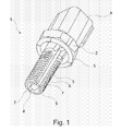
- Fig. 1 is a perspective view of an object 1 in the form of a bolt.
- the object 1 is provided with a bolt head 2 adapted to engage a driving tool, such as a spanner, and a threaded portion 3.
- a driving tool such as a spanner
- a threaded portion 3 At the bolt head 2 the object 1 is connected to a connector box 4 for communicating signals from the object 1 to an external device.
- an O-ring 5 Also at the bolt head 2 is arranged an O-ring 5. Thereby the object 1 may be fitted tightly in an opening being provided with a mating inner thread.
- the threaded portion 3 is provided with two sub-portions 6 where the thread is interrupted, i.e. there are no 'hills' and 'valleys' in the sub-portions 6, and the surface is therefore relatively smooth.
- the sub-portions 6 extend over the entire length of the threaded portion 3, thereby making it possible to establish an uninterrupted connection from one end of the threaded portion 3 to an opposite end of the threaded portion 3 along each of the sub-portions 6.
- a layer of electrically conducting material 7 is arranged along each of the sub-portions 6. Thereby the layer of electrically conducting material 7 establishes electrical connections between an end part 8 of the object 1 and the bolt head 2.
- Arranging the layer of electrically conducting material 7 along the sub-portions 6 has the advantage that a very thin layer may be applied without risking that the electrical connection is interrupted due to the 'hills' and 'valleys' formed by the threaded portion 3.
- a further advantage of arranging the layer of electrically conducting material 7 along the sub-portions 6 is that a relatively thick layer may be applied without risking that the thread is no longer able to fit into a mating inner thread of an opening. Such a relatively thick layer may, e.g., be used in case very weak signal are expected, or in case it is desired to transfer relatively high currents via the layer.
- the layer of electrically conductive material 7 forms a sensing device (not visible).
- the part of the layer of electrically conducting material 7 which is arranged along the sub-portions 6 establishes electrical connections between the sensing device and the connector box 4. Thereby it is possible to communicate with the sensing device when the object 1 is fixed in an opening with a mating inner thread.
- Fig. 2 is an exploded view of the object 1 of Fig. 1.
- connector pins 9 for connecting the bolt head 2 to the connector box 4 have been superimposed.
- the connector pins 9 may be press fitted into corresponding holes in the bolt head 2, thereby establishing an electrical connection to the object 1.
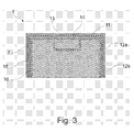
- Fig. 3 is a cross sectional view of a part of an object 1 according to an embodiment of the invention.
- the part shown in Fig. 3 may advantageously be positioned at the end part 8 of the object 1 shown in Figs. 1 and 2.
- the object 1 comprises a core part 10 made from an electrically conducting material and provided with a recess 11. At least part of the outer surface of the core part 10 is provided with a layer of electrically insulating material 12a. In the recess 11 and on top of the layer of electrically insulating material 12a is arranged a resilient material 13. On top of the resilient material 13 and covering at least part of the outer surface of the object 1 is arranged a layer of electrically conducting material 7.
- the layer of electrically conducting material 7 forms a sensing device.
- a second layer of electrically insulating material 12b On top of the electrically conducting material 7 is arranged a layer of wear resistant material 18 for protection of the layer of electrically conducting material 7, in particular the sensing device.
- the sensing device is a strain gauge operating in the following manner.
- the layer of electrically conducting material 7 is arranged in a specific pattern in the area 14 corresponding to the position of the resilient material 13. This will be explained in further detail below with reference to Figs. 4 and 5.
- the resilient material 14 When the object 1 is subjected to stress the resilient material 14 will be reversibly deformed. This will affect the pattern of the electrically conducting material 7 positioned in the area 14 in such a way that a change in the conductivity of the sensing device can be detected. This change in conductivity can be translated into a measure for the strain applied to the object 1, and the sensing device thereby functions as a strain gauge.
- Fig. 4 illustrates a first pattern of electrically conducting material 7.
- the pattern forms a sensing device 15 in the form of a strain gauge.
- the sensing device 15 comprises two meandering paths 16 arranged side-by-side in such a manner that the meandering patterns of the two paths 16 are arranged substantially perpendicularly with respect to each other.
- the sensing device 15 is stretched the distance between the longitudinal parts of the meandering pattern of one or both of the meandering paths 16 will increase, depending on the direction in which the sensing device 15 is stretched, as well as the amount of force applied to cause the stretching.
- This causes a change in the conductivity between the longitudinal parts of the meandering patterns of the sensing device 15.
- the sensing device 15 is capable of detecting a stress applied to the sensing device 15 as well as the direction in which the stress is applied.
- Fig. 5 illustrates a second pattern of electrically conducting material 7. Also in this case the pattern forms a sensing device 15 in the form of a strain gauge.
- the meandering paths 16 are arranged in a wedge shaped pattern. However, the paths 16 are still arranged substantially perpendicularly to each other, and the sensing device 15 is therefore capable of detecting the size as well as the direction of a stress applied to the sensing device 15, similarly to what is described above with reference to Fig. 4.
- Fig. 6 illustrates a third pattern of electrically conducting material 7.
- the pattern forms a sensing device 15 in the form of a thermocouple.
- the pattern of electrically conducting material 7 is formed by two different electrically conducting materials. The two materials are arranged in such a manner that they define a contact point 17 where electrical connection is established between the two parts of the pattern of electrically conducting material 7. Thereby a junction between the two materials is formed. A similar junction may be formed in another position which is held at a substantially constant temperature level, or at least at a temperature which is known.
- the sensing device 15, and thereby the contact point 17 is subjected to a change in temperature, the temperature difference between the two junctions will change correspondingly.
- an output voltage from the sensing device 15 is also changed due to the Peltier-Seebeck effect which is known per se. Accordingly, the sensing device 15 provides information of the temperature level at the position of the sensing device 15, and functions as a thermocouple.
- the contact point 17 may be provided by a larger overlap between the patterns of electrically conducting material 7.
- the tapered portions of the patterns 7 may be absent, and the two patterns 7 may simply overlap in a certain area of square or rectangular shape.
- the advantage of such a design is that contact between the two parts of the patterns of electrically conducting material 7 is ensured.
- the point where the temperature is measured will be less well-defined as compared to the embodiment shown in Fig. 6.
- Fig. 7 illustrates a fourth pattern of electrically conducting material 7.
- the pattern forms two separate conducting paths 7a, 7b which are arranged in an interleaved manner.
- the pattern forms a sensing device 15 in the form of a moisture sensor.
- the sensing device 15 operates in the following manner. When the sensing device 15 is subjected to a change in moisture level of the ambient air, the conductivity between the fingers of the interleaved pattern changes accordingly, and measuring this change in conductivity will thereby provide a measure for the moisture level of the ambient air, or other chemical species in cases where the substrate interacts with chemical species which may alter the conductivity between the conductors.
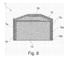
- Fig. 8 is a cross sectional view of a part of an object 1 according to an embodiment of the invention.
- the part shown in Fig. 8 may advantageously be positioned at the end part 8 of the object shown in Figs. 1 and 2.
- the object 1 comprises a core part 10 made from an electrically conducting material. At least part of the outer surface of the core part 10 is provided with a layer of electrically insulating material 12a. On top of the layer of insulating material 12a is arranged a layer of electrically conducting material 7.
- the layer of electrically conducting material 7 comprises two parts 7a, 7b. At an end region 19 of the object 1 the first part 7a and the second part 7b of the layer of electrically conducting material 7 are overlapping and spaced apart.
- a resilient material 13 is arranged between the parts 7a, 7b .
- a second layer of electrically insulating material 12b On top of the layer of electrically conducting material 7 is arranged a second layer of electrically insulating material 12b, and on top of this layer 12b is arranged a layer of wear resistant material 18.
- a pressure sensor is defined by the layer of electrically conducting material 7. The pressure sensor operates in the following manner.
- the two parts 7a, 7b of the layer of electrically conducting material 7 form a capacitor in region 19.
- the resilient material 13 will be reversibly deformed, thereby changing the distance between the two parts 7a, 7b. Accordingly, the capacitance of the capacitor formed by the two parts 7a, 7b is changed.
- a measure for the applied pressure can be obtained.
- the layer of electrically conducting material 7 forms a sensing device in form of a pressure sensor.
Landscapes
- Physics & Mathematics (AREA)
- General Physics & Mathematics (AREA)
- Measurement Of Length, Angles, Or The Like Using Electric Or Magnetic Means (AREA)
Applications Claiming Priority (1)
| Application Number | Priority Date | Filing Date | Title |
|---|---|---|---|
| DKPA200600493 | 2006-04-06 |
Publications (2)
| Publication Number | Publication Date |
|---|---|
| EP1843138A1 true EP1843138A1 (fr) | 2007-10-10 |
| EP1843138B1 EP1843138B1 (fr) | 2012-05-16 |
Family
ID=38171213
Family Applications (1)
| Application Number | Title | Priority Date | Filing Date |
|---|---|---|---|
| EP07105448A Not-in-force EP1843138B1 (fr) | 2006-04-06 | 2007-04-02 | Vis comportant une couche de matériau conducteur formant un capteur |
Country Status (3)
| Country | Link |
|---|---|
| US (1) | US7766547B2 (fr) |
| EP (1) | EP1843138B1 (fr) |
| CN (1) | CN101071082B (fr) |
Cited By (4)
| Publication number | Priority date | Publication date | Assignee | Title |
|---|---|---|---|---|
| EP2187222A1 (fr) * | 2008-11-13 | 2010-05-19 | BAE Systems PLC | Capteurs d'écoulement |
| WO2010055338A1 (fr) * | 2008-11-13 | 2010-05-20 | Bae Systems Plc | Capteurs d'écoulement |
| EP3279628A4 (fr) * | 2015-03-31 | 2018-12-05 | Nejilaw Inc. | Élément équipé d'une trajectoire de conduction, procédé de formation de motifs de trajectoire de conduction, et procédé permettant de mesurer des changements dans un élément |
| US11313740B2 (en) * | 2019-02-08 | 2022-04-26 | Fairfield Manufacturing Company, Inc. | Gearbox temperature measurement device |
Families Citing this family (32)
| Publication number | Priority date | Publication date | Assignee | Title |
|---|---|---|---|---|
| AU2003902259A0 (en) * | 2003-05-13 | 2003-05-29 | Telezygology Inc. | Improved assembly system |
| US8942483B2 (en) | 2009-09-14 | 2015-01-27 | Trimble Navigation Limited | Image-based georeferencing |
| DE102007037364A1 (de) * | 2007-08-08 | 2009-02-12 | Robert Bosch Gmbh | Flüssigkeitssensor |
| DE102007042789A1 (de) * | 2007-09-07 | 2009-03-12 | Robert Bosch Gmbh | Steckfühler zur Messung mindestens einer Eigenschaft eines fluiden Mediums |
| EP2376885A1 (fr) * | 2008-12-10 | 2011-10-19 | Weiss, Karsten | Corps soumis à la déformation pour détecteur de couple |
| US20100280788A1 (en) * | 2009-05-04 | 2010-11-04 | R. W. Becketi Corporation | Integrated multi-sensor component |
| US8950936B2 (en) * | 2009-07-10 | 2015-02-10 | Honda Motor Company Limited | Nail puncture test device having temperature measurement function |
| US8897541B2 (en) | 2009-09-14 | 2014-11-25 | Trimble Navigation Limited | Accurate digitization of a georeferenced image |
| US8855937B2 (en) | 2010-10-25 | 2014-10-07 | Trimble Navigation Limited | Crop characteristic estimation |
| US20120101784A1 (en) | 2010-10-25 | 2012-04-26 | Trimble Navigation Limited | Wide-area agricultural monitoring and prediction |
| US10115158B2 (en) | 2010-10-25 | 2018-10-30 | Trimble Inc. | Generating a crop recommendation |
| US9846848B2 (en) | 2010-10-25 | 2017-12-19 | Trimble Inc. | Exchanging water allocation credits |
| US9213905B2 (en) | 2010-10-25 | 2015-12-15 | Trimble Navigation Limited | Automatic obstacle location mapping |
| US9408342B2 (en) | 2010-10-25 | 2016-08-09 | Trimble Navigation Limited | Crop treatment compatibility |
| US9058633B2 (en) | 2010-10-25 | 2015-06-16 | Trimble Navigation Limited | Wide-area agricultural monitoring and prediction |
| US8768667B2 (en) | 2010-10-25 | 2014-07-01 | Trimble Navigation Limited | Water erosion management incorporating topography, soil type, and weather statistics |
| US8671741B2 (en) * | 2011-06-29 | 2014-03-18 | Trimble Navigation Limited | Extendable moisture content sensing system |
| CN103233966B (zh) * | 2012-12-21 | 2015-06-03 | 珠海一多监测科技有限公司 | 具有测温功能的智能螺栓 |
| US8992077B2 (en) * | 2013-03-07 | 2015-03-31 | Quantum Design International, Inc. | Ultrasensitive ratiometric capacitance dilatometer and related methods |
| DE102013209060A1 (de) * | 2013-05-16 | 2014-11-20 | Robert Bosch Gmbh | Vorrichtung zur Erfassung eines Drucks und einer Temperatur eines in einem Kanal strömenden fluiden Mediums |
| EP2813175A3 (fr) | 2013-06-14 | 2015-04-01 | Oticon A/s | Dispositif d'aide auditive avec interface cerveau-ordinateur |
| CN108778914A (zh) * | 2016-03-14 | 2018-11-09 | 卡特彼勒公司 | 履带销通信系统和方法 |
| CN106644147B (zh) * | 2016-11-23 | 2019-10-25 | 安徽瑞鑫自动化仪表有限公司 | 一种便于进行流体温度测量的温度传感器 |
| CN106768455B (zh) * | 2016-11-23 | 2019-11-29 | 安徽瑞鑫自动化仪表有限公司 | 一种温度传感器组件 |
| EP3441625B1 (fr) * | 2017-08-08 | 2020-06-17 | B&R Industrial Automation GmbH | Élément de montage à limitation de pression |
| KR102020988B1 (ko) * | 2017-09-28 | 2019-09-11 | 최홍천 | 응력을 감지하기 위한 커패시터형 저항 센서 |
| EP3769060B1 (fr) * | 2018-03-23 | 2025-03-12 | Watlow Electric Manufacturing Company | Sonde de détecteur de température à isolation thermique |
| DE102018115327B4 (de) * | 2018-06-26 | 2021-02-18 | Jumo Gmbh & Co. Kg | Temperatursensor |
| CN108801485B (zh) * | 2018-07-25 | 2024-07-23 | 佛山市顺德区美的洗涤电器制造有限公司 | 温度检测器和具有其的烹饪灶具 |
| WO2020205460A1 (fr) * | 2019-04-01 | 2020-10-08 | Schlumberger Technology Corporation | Dispositif de coupe instrumenté |
| WO2021157055A1 (fr) * | 2020-02-07 | 2021-08-12 | 日本電信電話株式会社 | Structure de gestion de couple de serrage pour boulon et son procédé |
| EP4409250A1 (fr) * | 2021-09-28 | 2024-08-07 | Krabo Srl | Procédé, appareil et système pour un élément de fixation ayant un système de surveillance sans fil |
Citations (6)
| Publication number | Priority date | Publication date | Assignee | Title |
|---|---|---|---|---|
| US4313341A (en) | 1978-12-07 | 1982-02-02 | Nippon Soken, Inc. | Torque detecting system for internal combustion engine |
| US4603455A (en) | 1983-04-12 | 1986-08-05 | Endress U. Hauser Gmbh U. Co. | Method for making a thin-film humidity sensor for measuring absolute humidity |
| US4904091A (en) | 1988-09-15 | 1990-02-27 | The United States Of America As Represented By The Administrator Of The National Aeronautics And Space Administration | Threaded average temperature thermocouple |
| US5044204A (en) | 1990-07-09 | 1991-09-03 | Teledyne Industries, Inc. | Device with strain gaged threaded portion |
| US5573335A (en) | 1994-05-25 | 1996-11-12 | Schinazi; Robert | Thin film temperature sensing device for measuring the operating temperature of a cutting tool |
| DE19703932A1 (de) | 1996-02-14 | 1998-08-06 | Fortech Hts Gmbh | Thermoelektrischer Sensor |
Family Cites Families (45)
| Publication number | Priority date | Publication date | Assignee | Title |
|---|---|---|---|---|
| US2600029A (en) * | 1946-11-12 | 1952-06-10 | Gerotor May Corp | Stress indicating bolt or stud |
| US3335382A (en) * | 1964-11-19 | 1967-08-08 | American Radiator & Standard C | Temperature probe |
| US4016762A (en) * | 1975-09-02 | 1977-04-12 | Modulus Corporation | Temperature indicator |
| US4294122A (en) * | 1979-07-12 | 1981-10-13 | General Dynamics Corporation | Fastener incorporating ultrasonic transducer |
| US4354725A (en) * | 1980-04-21 | 1982-10-19 | General Electric Co. | Insulated terminal assembly |
| US4548780A (en) * | 1981-01-27 | 1985-10-22 | Elmwood Sensors Limited | Sensing devices for mounting in chamber walls and a method of manufacture |
| DE3134166A1 (de) * | 1981-08-28 | 1983-03-10 | Robert Bosch Gmbh, 7000 Stuttgart | Temperaturfuehler |
| US4419652A (en) * | 1981-10-09 | 1983-12-06 | Bendix Autolite Corp. | Temperature sensor |
| US4429579A (en) * | 1981-10-26 | 1984-02-07 | Helm Instrument Co., Inc. | Tie rod tension sensor |
| US4495810A (en) * | 1983-04-20 | 1985-01-29 | General Electric Company | Probe mounting system |
| NZ206715A (en) * | 1983-12-22 | 1988-10-28 | Fisher & Paykel | Forming a thermistor temperature probe |
| US4575705A (en) * | 1984-02-17 | 1986-03-11 | Weed Instrument Co., Inc. | Temperature probe |
| SE452911B (sv) * | 1984-07-06 | 1987-12-21 | Birger Alvelid | Forfarande for framstellning av tillstandsgivare for mekaniska komponenter, jemte dylika mekaniska komponenter |
| JPH0648219B2 (ja) * | 1986-03-12 | 1994-06-22 | 日本特殊陶業株式会社 | 温度センサ |
| DE3616308C2 (de) * | 1986-05-14 | 1995-09-21 | Bosch Gmbh Robert | Sensor |
| US4963194A (en) * | 1987-01-12 | 1990-10-16 | Sam Mele | Adjustable depth thermocouple system and fitting |
| US4749415A (en) * | 1987-01-28 | 1988-06-07 | Westinghouse Electric Corp. | Fast response thermocouple element |
| SE460403B (sv) * | 1987-10-20 | 1989-10-09 | Birger Alvelid | Skaerverktyg foersett med tillstaandsgivare |
| US4841273A (en) * | 1987-12-18 | 1989-06-20 | Therm-O-Disc, Incorporated | High temperature sensing apparatus |
| US4991976A (en) * | 1989-05-31 | 1991-02-12 | Weed Instruments Company, Inc. | Temperature sensor probe apparatus and method for improving time response |
| US5076708A (en) * | 1990-05-14 | 1991-12-31 | Pierson Mark W | Threaded temperature indicating plug for hot oil housings such as transmissions and the like |
| GB9026034D0 (en) * | 1990-11-29 | 1991-01-16 | Rolls Royce Plc | A fluid temperature measuring device |
| US5106580A (en) * | 1991-02-14 | 1992-04-21 | Metal Samples Company, Inc. | Probe insertion and retraction tool |
| US5203278A (en) * | 1991-12-31 | 1993-04-20 | Commonwealth Technology Inc. | Temperature warning device |
| JP3182910B2 (ja) * | 1992-09-14 | 2001-07-03 | 株式会社明電舎 | 温度センサ |
| US5451868A (en) * | 1993-05-28 | 1995-09-19 | Arthur Allen Manufacturing Company | Changeable divider and index for a vehicle speed and distance transducer including a hall effect sensor |
| US5380092A (en) * | 1993-10-07 | 1995-01-10 | Alain; George | Fluid temperature indicator |
| US5461923A (en) * | 1994-05-16 | 1995-10-31 | Raymond Engineering Inc. | Acoustic transducer, transducerized fastener and method of manufacture |
| US5594405A (en) * | 1994-08-26 | 1997-01-14 | Microhydraulics, Inc. | Pressure transducer with pressure sensitive conductor |
| DE19512813C1 (de) * | 1995-04-05 | 1996-06-20 | Sensotherm Temperatursensorik | Verfahren zur Herstellung von Bauelementen |
| US5697706A (en) * | 1995-12-26 | 1997-12-16 | Chrysler Corporation | Multi-point temperature probe |
| US5642717A (en) * | 1996-07-01 | 1997-07-01 | Ford Motor Company | Temperature sensing system for an internal combustion engine |
| JP3124506B2 (ja) * | 1997-03-14 | 2001-01-15 | 白光株式会社 | ヒータ・センサ複合体 |
| US6095680A (en) * | 1997-05-05 | 2000-08-01 | Baratta; Francis I. | Nondestructive fraudulent fastener screening and composition determination device |
| US5945665A (en) * | 1997-05-09 | 1999-08-31 | Cidra Corporation | Bolt, stud or fastener having an embedded fiber optic Bragg Grating sensor for sensing tensioning strain |
| NO322272B1 (no) * | 1999-03-26 | 2006-09-04 | Kongsberg Maritime As | Sensor og system for overvaking av temperatur inne i vanskelig tilgjengelige, bevegelige deler |
| US6341892B1 (en) * | 2000-02-03 | 2002-01-29 | George Schmermund | Resistance thermometer probe |
| JP2001282396A (ja) * | 2000-03-24 | 2001-10-12 | Internatl Business Mach Corp <Ibm> | 発電機構、コンピュータ装置及び電子機器 |
| CN2485639Y (zh) * | 2000-07-28 | 2002-04-10 | 武汉理工大学 | 发动机气缸套内壁温度测量传感器 |
| TW593993B (en) * | 2003-11-03 | 2004-06-21 | Oriental System Technology Inc | Electrical thermometer |
| DE102005022087B4 (de) * | 2004-05-17 | 2013-10-31 | Denso Corporation | Druckerfassungsvorrichtung |
| US20060039446A1 (en) * | 2004-08-23 | 2006-02-23 | Yung-Ku Lee | Fast response clinical thermometer |
| US7465086B1 (en) * | 2005-03-05 | 2008-12-16 | Foreman Instrumentation & Controls, Inc. | Adjustable length thermowell |
| WO2006133702A1 (fr) * | 2005-06-15 | 2006-12-21 | Danfoss A/S | Objet comprenant une structure en plusieurs couches alternées conductrices et isolantes |
| US8137625B2 (en) * | 2007-01-22 | 2012-03-20 | Ngk Spark Plug Co., Ltd. | Urea sensor |
-
2007
- 2007-04-02 EP EP07105448A patent/EP1843138B1/fr not_active Not-in-force
- 2007-04-05 US US11/784,034 patent/US7766547B2/en active Active
- 2007-04-06 CN CN2007101288162A patent/CN101071082B/zh not_active Expired - Fee Related
Patent Citations (6)
| Publication number | Priority date | Publication date | Assignee | Title |
|---|---|---|---|---|
| US4313341A (en) | 1978-12-07 | 1982-02-02 | Nippon Soken, Inc. | Torque detecting system for internal combustion engine |
| US4603455A (en) | 1983-04-12 | 1986-08-05 | Endress U. Hauser Gmbh U. Co. | Method for making a thin-film humidity sensor for measuring absolute humidity |
| US4904091A (en) | 1988-09-15 | 1990-02-27 | The United States Of America As Represented By The Administrator Of The National Aeronautics And Space Administration | Threaded average temperature thermocouple |
| US5044204A (en) | 1990-07-09 | 1991-09-03 | Teledyne Industries, Inc. | Device with strain gaged threaded portion |
| US5573335A (en) | 1994-05-25 | 1996-11-12 | Schinazi; Robert | Thin film temperature sensing device for measuring the operating temperature of a cutting tool |
| DE19703932A1 (de) | 1996-02-14 | 1998-08-06 | Fortech Hts Gmbh | Thermoelektrischer Sensor |
Cited By (6)
| Publication number | Priority date | Publication date | Assignee | Title |
|---|---|---|---|---|
| EP2187222A1 (fr) * | 2008-11-13 | 2010-05-19 | BAE Systems PLC | Capteurs d'écoulement |
| WO2010055338A1 (fr) * | 2008-11-13 | 2010-05-20 | Bae Systems Plc | Capteurs d'écoulement |
| US8578769B2 (en) | 2008-11-13 | 2013-11-12 | Bae Systems Plc. | Flow sensors |
| EP3279628A4 (fr) * | 2015-03-31 | 2018-12-05 | Nejilaw Inc. | Élément équipé d'une trajectoire de conduction, procédé de formation de motifs de trajectoire de conduction, et procédé permettant de mesurer des changements dans un élément |
| US11313740B2 (en) * | 2019-02-08 | 2022-04-26 | Fairfield Manufacturing Company, Inc. | Gearbox temperature measurement device |
| US11796397B2 (en) | 2019-02-08 | 2023-10-24 | Fairfield Manufacturing Company, Inc. | Gearbox temperature measurement device |
Also Published As
| Publication number | Publication date |
|---|---|
| CN101071082B (zh) | 2010-09-29 |
| US20070234818A1 (en) | 2007-10-11 |
| EP1843138B1 (fr) | 2012-05-16 |
| US7766547B2 (en) | 2010-08-03 |
| CN101071082A (zh) | 2007-11-14 |
Similar Documents
| Publication | Publication Date | Title |
|---|---|---|
| US7766547B2 (en) | Object having a layer of conducting material forming a sensing device | |
| US6606911B2 (en) | Pressure sensors | |
| EP2162711B1 (fr) | Ensemble de capteur de température et son procédé de fabrication | |
| CN107817015A (zh) | 集成式压力与温度传感器 | |
| US4318073A (en) | Temperature sensor | |
| WO2003052387A3 (fr) | Capteur de ph avec mise a la masse d'une solution interne | |
| US5720556A (en) | Temperature sensor probe | |
| MXPA97003843A (es) | Sensor de temperatura con resistor de medicion | |
| KR102587393B1 (ko) | 통합 압력 및 온도 센서 | |
| US20020090019A1 (en) | Temperature sensor | |
| JPS62220822A (ja) | ピエゾ抵抗型力測定要素 | |
| US6997059B2 (en) | Pressure sensor | |
| EP0064798A1 (fr) | Dispositif capteurs pouvant être fixés dans la paroi d'une chambre de mesure et procédé de fabrication | |
| US10247615B2 (en) | Sensor assemblies and methods of making same | |
| US6860635B2 (en) | Sensor and housing with adjustable spacing element | |
| EP1963788A2 (fr) | Capteur de pression comprenant une fiche technique électronique | |
| US7240558B2 (en) | Pressure sensor | |
| US20050103110A1 (en) | Integrated pressure and temperature sensor | |
| EP3407046B1 (fr) | Capteur de force flexible microscopique | |
| US6962085B2 (en) | Pressure detector having elongate housing containing pressure-sensitive element therein | |
| US10514312B2 (en) | Hydraulic pressure sensor for a vehicle | |
| US6580042B1 (en) | Circuit board integrated pressure switch | |
| EP0710827A2 (fr) | Détecteur de pression de combustion et procédé de fabrication | |
| EP0953832A2 (fr) | Capteur de pression capacitif à erreur de sortie réduite | |
| EP1552260B1 (fr) | Capteur de pression et fabrication de celui-ci |
Legal Events
| Date | Code | Title | Description |
|---|---|---|---|
| PUAI | Public reference made under article 153(3) epc to a published international application that has entered the european phase |
Free format text: ORIGINAL CODE: 0009012 |
|
| AK | Designated contracting states |
Kind code of ref document: A1 Designated state(s): AT BE BG CH CY CZ DE DK EE ES FI FR GB GR HU IE IS IT LI LT LU LV MC MT NL PL PT RO SE SI SK TR |
|
| AX | Request for extension of the european patent |
Extension state: AL BA HR MK YU |
|
| 17P | Request for examination filed |
Effective date: 20070903 |
|
| AKX | Designation fees paid |
Designated state(s): AT BE BG CH CY CZ DE DK EE ES FI FR GB GR HU IE IS IT LI LT LU LV MC MT NL PL PT RO SE SI SK TR |
|
| 17Q | First examination report despatched |
Effective date: 20091202 |
|
| REG | Reference to a national code |
Ref country code: DE Ref legal event code: R079 Ref document number: 602007022594 Country of ref document: DE Free format text: PREVIOUS MAIN CLASS: G01K0001140000 Ipc: G01D0011240000 |
|
| GRAP | Despatch of communication of intention to grant a patent |
Free format text: ORIGINAL CODE: EPIDOSNIGR1 |
|
| RIC1 | Information provided on ipc code assigned before grant |
Ipc: G01K 7/02 20060101ALI20111007BHEP Ipc: G01N 27/12 20060101ALI20111007BHEP Ipc: G01D 11/30 20060101ALI20111007BHEP Ipc: G01D 11/24 20060101AFI20111007BHEP Ipc: G01K 1/14 20060101ALI20111007BHEP Ipc: G01L 5/00 20060101ALI20111007BHEP Ipc: G01L 9/00 20060101ALI20111007BHEP Ipc: G01L 1/22 20060101ALI20111007BHEP |
|
| RAP1 | Party data changed (applicant data changed or rights of an application transferred) |
Owner name: SAUER-DANFOSS HOLDING APS |
|
| RAP1 | Party data changed (applicant data changed or rights of an application transferred) |
Owner name: SAUER-DANFOSS APS |
|
| GRAS | Grant fee paid |
Free format text: ORIGINAL CODE: EPIDOSNIGR3 |
|
| GRAA | (expected) grant |
Free format text: ORIGINAL CODE: 0009210 |
|
| AK | Designated contracting states |
Kind code of ref document: B1 Designated state(s): AT BE BG CH CY CZ DE DK EE ES FI FR GB GR HU IE IS IT LI LT LU LV MC MT NL PL PT RO SE SI SK TR |
|
| REG | Reference to a national code |
Ref country code: GB Ref legal event code: FG4D |
|
| REG | Reference to a national code |
Ref country code: CH Ref legal event code: EP |
|
| REG | Reference to a national code |
Ref country code: AT Ref legal event code: REF Ref document number: 558302 Country of ref document: AT Kind code of ref document: T Effective date: 20120615 |
|
| REG | Reference to a national code |
Ref country code: IE Ref legal event code: FG4D |
|
| REG | Reference to a national code |
Ref country code: DE Ref legal event code: R096 Ref document number: 602007022594 Country of ref document: DE Effective date: 20120719 |
|
| REG | Reference to a national code |
Ref country code: NL Ref legal event code: VDEP Effective date: 20120516 |
|
| REG | Reference to a national code |
Ref country code: LT Ref legal event code: MG4D Effective date: 20120516 |
|
| PG25 | Lapsed in a contracting state [announced via postgrant information from national office to epo] |
Ref country code: LT Free format text: LAPSE BECAUSE OF FAILURE TO SUBMIT A TRANSLATION OF THE DESCRIPTION OR TO PAY THE FEE WITHIN THE PRESCRIBED TIME-LIMIT Effective date: 20120516 Ref country code: PL Free format text: LAPSE BECAUSE OF FAILURE TO SUBMIT A TRANSLATION OF THE DESCRIPTION OR TO PAY THE FEE WITHIN THE PRESCRIBED TIME-LIMIT Effective date: 20120516 Ref country code: CY Free format text: LAPSE BECAUSE OF FAILURE TO SUBMIT A TRANSLATION OF THE DESCRIPTION OR TO PAY THE FEE WITHIN THE PRESCRIBED TIME-LIMIT Effective date: 20120516 Ref country code: SE Free format text: LAPSE BECAUSE OF FAILURE TO SUBMIT A TRANSLATION OF THE DESCRIPTION OR TO PAY THE FEE WITHIN THE PRESCRIBED TIME-LIMIT Effective date: 20120516 Ref country code: IS Free format text: LAPSE BECAUSE OF FAILURE TO SUBMIT A TRANSLATION OF THE DESCRIPTION OR TO PAY THE FEE WITHIN THE PRESCRIBED TIME-LIMIT Effective date: 20120916 Ref country code: FI Free format text: LAPSE BECAUSE OF FAILURE TO SUBMIT A TRANSLATION OF THE DESCRIPTION OR TO PAY THE FEE WITHIN THE PRESCRIBED TIME-LIMIT Effective date: 20120516 |
|
| REG | Reference to a national code |
Ref country code: AT Ref legal event code: MK05 Ref document number: 558302 Country of ref document: AT Kind code of ref document: T Effective date: 20120516 |
|
| PG25 | Lapsed in a contracting state [announced via postgrant information from national office to epo] |
Ref country code: SI Free format text: LAPSE BECAUSE OF FAILURE TO SUBMIT A TRANSLATION OF THE DESCRIPTION OR TO PAY THE FEE WITHIN THE PRESCRIBED TIME-LIMIT Effective date: 20120516 Ref country code: LV Free format text: LAPSE BECAUSE OF FAILURE TO SUBMIT A TRANSLATION OF THE DESCRIPTION OR TO PAY THE FEE WITHIN THE PRESCRIBED TIME-LIMIT Effective date: 20120516 Ref country code: PT Free format text: LAPSE BECAUSE OF FAILURE TO SUBMIT A TRANSLATION OF THE DESCRIPTION OR TO PAY THE FEE WITHIN THE PRESCRIBED TIME-LIMIT Effective date: 20120917 Ref country code: GR Free format text: LAPSE BECAUSE OF FAILURE TO SUBMIT A TRANSLATION OF THE DESCRIPTION OR TO PAY THE FEE WITHIN THE PRESCRIBED TIME-LIMIT Effective date: 20120817 |
|
| PG25 | Lapsed in a contracting state [announced via postgrant information from national office to epo] |
Ref country code: BE Free format text: LAPSE BECAUSE OF FAILURE TO SUBMIT A TRANSLATION OF THE DESCRIPTION OR TO PAY THE FEE WITHIN THE PRESCRIBED TIME-LIMIT Effective date: 20120516 |
|
| PG25 | Lapsed in a contracting state [announced via postgrant information from national office to epo] |
Ref country code: RO Free format text: LAPSE BECAUSE OF FAILURE TO SUBMIT A TRANSLATION OF THE DESCRIPTION OR TO PAY THE FEE WITHIN THE PRESCRIBED TIME-LIMIT Effective date: 20120516 Ref country code: CZ Free format text: LAPSE BECAUSE OF FAILURE TO SUBMIT A TRANSLATION OF THE DESCRIPTION OR TO PAY THE FEE WITHIN THE PRESCRIBED TIME-LIMIT Effective date: 20120516 Ref country code: AT Free format text: LAPSE BECAUSE OF FAILURE TO SUBMIT A TRANSLATION OF THE DESCRIPTION OR TO PAY THE FEE WITHIN THE PRESCRIBED TIME-LIMIT Effective date: 20120516 Ref country code: SK Free format text: LAPSE BECAUSE OF FAILURE TO SUBMIT A TRANSLATION OF THE DESCRIPTION OR TO PAY THE FEE WITHIN THE PRESCRIBED TIME-LIMIT Effective date: 20120516 Ref country code: DK Free format text: LAPSE BECAUSE OF FAILURE TO SUBMIT A TRANSLATION OF THE DESCRIPTION OR TO PAY THE FEE WITHIN THE PRESCRIBED TIME-LIMIT Effective date: 20120516 Ref country code: EE Free format text: LAPSE BECAUSE OF FAILURE TO SUBMIT A TRANSLATION OF THE DESCRIPTION OR TO PAY THE FEE WITHIN THE PRESCRIBED TIME-LIMIT Effective date: 20120516 Ref country code: NL Free format text: LAPSE BECAUSE OF FAILURE TO SUBMIT A TRANSLATION OF THE DESCRIPTION OR TO PAY THE FEE WITHIN THE PRESCRIBED TIME-LIMIT Effective date: 20120516 |
|
| PG25 | Lapsed in a contracting state [announced via postgrant information from national office to epo] |
Ref country code: IT Free format text: LAPSE BECAUSE OF FAILURE TO SUBMIT A TRANSLATION OF THE DESCRIPTION OR TO PAY THE FEE WITHIN THE PRESCRIBED TIME-LIMIT Effective date: 20120516 |
|
| PLBE | No opposition filed within time limit |
Free format text: ORIGINAL CODE: 0009261 |
|
| STAA | Information on the status of an ep patent application or granted ep patent |
Free format text: STATUS: NO OPPOSITION FILED WITHIN TIME LIMIT |
|
| 26N | No opposition filed |
Effective date: 20130219 |
|
| PG25 | Lapsed in a contracting state [announced via postgrant information from national office to epo] |
Ref country code: ES Free format text: LAPSE BECAUSE OF FAILURE TO SUBMIT A TRANSLATION OF THE DESCRIPTION OR TO PAY THE FEE WITHIN THE PRESCRIBED TIME-LIMIT Effective date: 20120827 |
|
| REG | Reference to a national code |
Ref country code: DE Ref legal event code: R097 Ref document number: 602007022594 Country of ref document: DE Effective date: 20130219 |
|
| PG25 | Lapsed in a contracting state [announced via postgrant information from national office to epo] |
Ref country code: BG Free format text: LAPSE BECAUSE OF FAILURE TO SUBMIT A TRANSLATION OF THE DESCRIPTION OR TO PAY THE FEE WITHIN THE PRESCRIBED TIME-LIMIT Effective date: 20120816 |
|
| PG25 | Lapsed in a contracting state [announced via postgrant information from national office to epo] |
Ref country code: MC Free format text: LAPSE BECAUSE OF FAILURE TO SUBMIT A TRANSLATION OF THE DESCRIPTION OR TO PAY THE FEE WITHIN THE PRESCRIBED TIME-LIMIT Effective date: 20120516 |
|
| REG | Reference to a national code |
Ref country code: CH Ref legal event code: PL |
|
| REG | Reference to a national code |
Ref country code: IE Ref legal event code: MM4A |
|
| PG25 | Lapsed in a contracting state [announced via postgrant information from national office to epo] |
Ref country code: CH Free format text: LAPSE BECAUSE OF NON-PAYMENT OF DUE FEES Effective date: 20130430 Ref country code: LI Free format text: LAPSE BECAUSE OF NON-PAYMENT OF DUE FEES Effective date: 20130430 |
|
| PG25 | Lapsed in a contracting state [announced via postgrant information from national office to epo] |
Ref country code: IE Free format text: LAPSE BECAUSE OF NON-PAYMENT OF DUE FEES Effective date: 20130402 |
|
| REG | Reference to a national code |
Ref country code: FR Ref legal event code: CD Owner name: DANFOSS POWER SOLUTIONS APS, DK Effective date: 20140527 |
|
| REG | Reference to a national code |
Ref country code: DE Ref legal event code: R081 Ref document number: 602007022594 Country of ref document: DE Owner name: DANFOSS POWER SOLUTIONS APS, DK Free format text: FORMER OWNER: SAUER-DANFOSS APS, NORDBORG, DK Effective date: 20140702 Ref country code: DE Ref legal event code: R081 Ref document number: 602007022594 Country of ref document: DE Owner name: DANFOSS POWER SOLUTIONS APS, DK Free format text: FORMER OWNER: SAUER-DANFOSS APS, NORDBORG, DK Effective date: 20120525 |
|
| REG | Reference to a national code |
Ref country code: DE Ref legal event code: R081 Ref document number: 602007022594 Country of ref document: DE Owner name: DANFOSS POWER SOLUTIONS APS, DK Free format text: FORMER OWNER: DANFOSS POWER SOLUTIONS APS, NORDBORG, DK Effective date: 20140819 |
|
| PG25 | Lapsed in a contracting state [announced via postgrant information from national office to epo] |
Ref country code: MT Free format text: LAPSE BECAUSE OF FAILURE TO SUBMIT A TRANSLATION OF THE DESCRIPTION OR TO PAY THE FEE WITHIN THE PRESCRIBED TIME-LIMIT Effective date: 20120516 |
|
| REG | Reference to a national code |
Ref country code: FR Ref legal event code: PLFP Year of fee payment: 9 |
|
| PG25 | Lapsed in a contracting state [announced via postgrant information from national office to epo] |
Ref country code: TR Free format text: LAPSE BECAUSE OF FAILURE TO SUBMIT A TRANSLATION OF THE DESCRIPTION OR TO PAY THE FEE WITHIN THE PRESCRIBED TIME-LIMIT Effective date: 20120516 |
|
| PG25 | Lapsed in a contracting state [announced via postgrant information from national office to epo] |
Ref country code: LU Free format text: LAPSE BECAUSE OF NON-PAYMENT OF DUE FEES Effective date: 20130402 Ref country code: HU Free format text: LAPSE BECAUSE OF FAILURE TO SUBMIT A TRANSLATION OF THE DESCRIPTION OR TO PAY THE FEE WITHIN THE PRESCRIBED TIME-LIMIT; INVALID AB INITIO Effective date: 20070402 |
|
| REG | Reference to a national code |
Ref country code: FR Ref legal event code: PLFP Year of fee payment: 10 |
|
| REG | Reference to a national code |
Ref country code: FR Ref legal event code: PLFP Year of fee payment: 11 |
|
| REG | Reference to a national code |
Ref country code: FR Ref legal event code: PLFP Year of fee payment: 12 |
|
| PGFP | Annual fee paid to national office [announced via postgrant information from national office to epo] |
Ref country code: FR Payment date: 20230328 Year of fee payment: 17 |
|
| PGFP | Annual fee paid to national office [announced via postgrant information from national office to epo] |
Ref country code: GB Payment date: 20230302 Year of fee payment: 17 |
|
| PGFP | Annual fee paid to national office [announced via postgrant information from national office to epo] |
Ref country code: DE Payment date: 20230307 Year of fee payment: 17 |
|
| REG | Reference to a national code |
Ref country code: DE Ref legal event code: R119 Ref document number: 602007022594 Country of ref document: DE |
|
| GBPC | Gb: european patent ceased through non-payment of renewal fee |
Effective date: 20240402 |
|
| PG25 | Lapsed in a contracting state [announced via postgrant information from national office to epo] |
Ref country code: DE Free format text: LAPSE BECAUSE OF NON-PAYMENT OF DUE FEES Effective date: 20241105 |
|
| PG25 | Lapsed in a contracting state [announced via postgrant information from national office to epo] |
Ref country code: GB Free format text: LAPSE BECAUSE OF NON-PAYMENT OF DUE FEES Effective date: 20240402 |
|
| PG25 | Lapsed in a contracting state [announced via postgrant information from national office to epo] |
Ref country code: FR Free format text: LAPSE BECAUSE OF NON-PAYMENT OF DUE FEES Effective date: 20240430 |
|
| PG25 | Lapsed in a contracting state [announced via postgrant information from national office to epo] |
Ref country code: GB Free format text: LAPSE BECAUSE OF NON-PAYMENT OF DUE FEES Effective date: 20240402 Ref country code: FR Free format text: LAPSE BECAUSE OF NON-PAYMENT OF DUE FEES Effective date: 20240430 Ref country code: DE Free format text: LAPSE BECAUSE OF NON-PAYMENT OF DUE FEES Effective date: 20241105 |