EP1843236A2 - Boîtier pour unité hôte doublement pliable pour ordinateur - Google Patents
Boîtier pour unité hôte doublement pliable pour ordinateur Download PDFInfo
- Publication number
- EP1843236A2 EP1843236A2 EP07105138A EP07105138A EP1843236A2 EP 1843236 A2 EP1843236 A2 EP 1843236A2 EP 07105138 A EP07105138 A EP 07105138A EP 07105138 A EP07105138 A EP 07105138A EP 1843236 A2 EP1843236 A2 EP 1843236A2
- Authority
- EP
- European Patent Office
- Prior art keywords
- unit case
- connecting rod
- host unit
- plate member
- dually
- Prior art date
- Legal status (The legal status is an assumption and is not a legal conclusion. Google has not performed a legal analysis and makes no representation as to the accuracy of the status listed.)
- Withdrawn
Links
Images





Classifications
-
- G—PHYSICS
- G06—COMPUTING OR CALCULATING; COUNTING
- G06F—ELECTRIC DIGITAL DATA PROCESSING
- G06F1/00—Details not covered by groups G06F3/00 - G06F13/00 and G06F21/00
- G06F1/16—Constructional details or arrangements
- G06F1/18—Packaging or power distribution
- G06F1/181—Enclosures
Definitions
- the present invention is related to a host unit case of a personal computer and particularly to a built-up type host unit case of a computer.
- the host unit case is employed to receive electronic devices such as a main board, hard disks, optical disk drives, floppy disk drives and power supply device. Usually, the host unit case is set up with an unchangeable structure.
- the composite type host unit case has prior art such as US 6,961,236 and Taiwan Utility model publication No. M258544 .
- US 6,961,236 discloses a computer chassis and Taiwan Utility model publication No. M258544 discloses a host unit case to meet specifications of ATX and BTX.
- Taiwan Patent Publication No. 468811 discloses a host unit case for an industrial computer.
- Taiwan Patent Publication No. 490120 discloses a composite computer chassis.
- Taiwan Patent Publication No. 474423 discloses a computer chassis free from aid of hand tools.
- Taiwan Patent Publication No. 490120 discloses a composite type computer chassis.
- Taiwan Patent Publication No. 531142 discloses a composite type computer chassis assembly.
- Taiwan Patent Publication No. 474423 provides the front and rear cover plates, which are pivotally joined to a bottom plate with head pins, two frame plates for a big floppy disk drive, which are pivotally joined to the front and rear cover plates, and a cover plate for a small floppy disk drive is assembled to a frame plate and is fixedly hung to the bottom of frame plate for the big floppy disk drive. Further, four L shaped plates are fixed at four corners of the bottom plate to be joined to the two cover plates firmly. Finally, two lateral cover plates are hooked to the lateral sides of the preceding structure and fastened with set screws after the main board and the power supply frame being mounted to the preceding structure to complete the whole assembly of the computer chassis. The parts of the computer chassis are packaged separately such that less space is required for storage.
- the primary object is to provide a dually foldable host unit case for a computer with which the host unit case can be completely set up easily and quickly to enhance fun while the host unit case being set up by the user.
- Another object is to provide a dually foldable host unit case for a computer with which the parts can be gathered together and reduced in a small volume while packaging for lowering delivery cost and saving storage space.
- a dually foldable host unit case for a computer is capable of being reduced volume thereof while packaging and being completely set up conveniently and quickly and comprises:
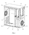
- Fig. 1 is a perspective view of the first embodiment of a dually foldable host unit case for a computer according to the present invention
- Fig. 2A is a perspective view illustrating the first plate in association with the upper cover and the lower cover in the first embodiment of the present invention
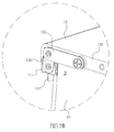
- Fig. 2B is an enlarged perspective view of the portion in the dashed circle in Fig. 2A;
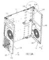
- Fig. 3A is a perspective view illustrating the first plate in association with the front wall and the rear wall in the first embodiment of the present invention
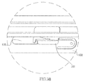
- Fig. 3B is an enlarged perspective view of the portion in the dashed circle in Fig. 3A;
- Fig. 4A is a perspective view illustrating the first plate in association with first support member and the second support member in the first embodiment of the present invention
- Fig. 4B is an enlarged perspective view illustrating the portion in one of the dashed circles of Fig. 4A;
- Fig. 4C is an enlarged perspective view illustrating the portion in another dashed circle of Fig. 4A;
- Fig. 5A is a perspective view illustrating the upper cover and the lower cover in association with the lateral plate in the first embodiment of the present invention
- Fig. 5B is an enlarged perspective view illustrating the portion in one of the dashed circles of Fig. 5A;
- Fig. 5C is a perspective view illustrating the upper cover and the lower cover in association with the lateral plate in the first embodiment of the present invention
- Fig. 6 is a perspective view of the second embodiment of the dually foldable host unit case according to the present invention.
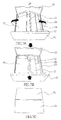
- Figs. 7A, 7B and 7C are perspective views illustrating steps to fold the second embodiment of the dually foldable host unit case according to the present invention.
- the first embodiment of a dually foldable host unit case according to the present invention is capable of being reduced volume thereof for packaging and being completely set up conveniently and quickly.
- the host unit case 10 includes a first plate member 11, an upper cover 12 and a lower cover 13.
- the first plate member 11 is mounted with a main board.
- the upper cover 12 extends downward a front margin frame 121, a rear margin frame 122, a left margin frame 123 and a right margin frame 124 at the four sides thereof.
- the front and rear margin frames 121, 122 pivotally connect with an end of a first connecting rod 125 respectively. Another end of the connecting rod 125 pivotally connects with an end of the second connecting rod 126.
- Another end of the second connecting rod 126 pivotally connects with two first lugs 111, which corresponds to each other.
- the two first lugs 111 are joined to the tops of the front and rear ends of the first plate member 11 respectively such that the left side end of the upper cover 12 pivotally connects with the upper end of the first plate member 11 and the upper end of the first plate member 11 is disposed at the inner side of the left margin frame 123 of the upper cover 12.
- the lower cover 13 extends upward a front margin frame 131, a rear margin frame 132, a left margin frame 133 and a right margin frame 134 at the four sides thereof.
- the left side end of the lower cover 13 pivotally connects with the lower end of the first plate member 11 and the lower end of the first plate member 11 is disposed at the inner side of the left margin frame 133 of the lower cover 13.
- the pivotal connecting structure between the lower cover 13 and first plate member 11 is the same as that between the upper cover 12 and the first plate member 11. No further detail will be described.
- the right margin frame 124 of the upper cover 12 and right margin frame 134 of the lower cover 13 are moved along arrows A and B of Fig. 2A to be close to the first plate member 11.
- a front wall 14 extends rearward an upper margin frame 141, a lower margin frame 142 and a right margin frame 143.
- the upper and lower margin frames 141, 142 of the front wall 14 pivotally connect with an end of a third connecting rod 144 respectively.
- Another end of the third connecting rod 144 pivotally connects with a fourth connecting rod 145.
- Another end of the respective fourth connecting rod 145 pivotally connects with a second lug 112.
- the two lugs 112 are joined to the upper and lower ends of the front side of the first plate member 11 such that the left lateral end of the front wall 14 is capable of pivotally connecting the front side of the first plate member 11 and the upper and lower ends of the front wall 14 are disposed at the inner sides of the front margin frame 121 of the upper cover 12 and the front margin frame 131 of the lower cover 13.
- the pivotal end between the fourth connecting rod 145 and the third connecting rod 144 can move relative to the second lugs 112 along direction indicated by an arrow E shown in Fig. 3B.
- the pivotal end between the third connecting rod 144 and the upper margin frame 144 can move relative to the fourth connecting rod 145 along direction indicated by an arrow F shown in Fig. 3B.
- the upper margin frame 141 can move relative to the third connecting rod 144 along direction indicated by arrow G shown in Fig. 3B. In this way, the front wall 14 is away the first plate 11 a bigger gap for receiving the first and second support members 16, 17 while the front wall 14 is folded to the lateral side of the first plate 11 as shown in Fig. 4A.
- a rear wall 15 extends forward an upper margin frame 151, a lower margin frame 152 and a right margin frame 153. The left side end of the rear wall 15 pivotally connects with the rear end of the first plate member 11 and the upper and lower ends of the rear wall 15 are disposed at the inner sides of the rear margin frame 122 of the upper cover 12 and the rear margin frame 132 of the lower cover 13.
- the pivotal structure of the rear wall 15 and the first plate member 11 is the same as that of the front wall 14 and the first plate member 11. No further detail will be described.
- the left margin frame 143 of the front wall 14 and right margin frame 153 of the rear wall 15 can move along direction indicated by allows C and D shown in Fig. 3A to press the first plate member 11.
- a foldable first support member 16 has a left partition 161 and a right partition 162.
- the left partition 161 pivotally connects with a pivotal plate element 163, 164 at both ends thereof and the right partition 162 pivotally connects with a pivotal plate element 165, 166 at both ends thereof.
- a connecting rod 167 is disposed between the pivotal plate elements 163 and 165 with both ends of the connecting rod being pivotally connected to the pivotal plate elements 163 and 165 respectively.
- Another connecting rod 167 is disposed between the pivotal plate elements 164 and 166 with both ends of the connecting rod being pivotally connected to the pivotal plate elements 164 and 166 respectively.
- a foldable second support member 17 has a left partition 171 and a right partition 172.
- the left partition 171 pivotally connects with a pivotal plate element 173, 174 at both ends thereof and the right partition 172 pivotally connects with a pivotal plate element 175, 176 at both ends thereof.
- a connecting rod 177 is disposed between the pivotal plate elements 173 and 175 with both ends of the connecting rod being pivotally connected to the pivotal plate elements 173 and 175 respectively.
- Another connecting rod 177 is disposed between the pivotal plate elements 174 and 176 with both ends of the connecting rod being pivotally connected to the pivotal plate elements 174 and 176 respectively.
- a connecting rod 178 is disposed between the pivotal plate elements 173 and a fourth lug 114 with both ends of the connecting rod being pivotally connected to the pivotal plate elements 173 and the fourth lug I14 respectively.
- Another connecting rod 178 is disposed between the pivotal plate elements 174 and another fourth lug 114 with both ends of the connecting rod being pivotally connected to the pivotal plate elements 174 and the another fourth lug 114 respectively.
- the fourth lugs 114 are joined to the first plate member 11.
- the left and right partitions 161, 171 of the first and second support members 16, 17 pivotally connect with the first plate member 11.
- the left partitions 161, 171 and the right partitions 162, 172 are pivotally connected to each other with four connecting rods such that the right partitions 162, 172 are capable of moving along arrows H, I shown in Fig. 4A to contact the left partitions 161, 171 against the first plate member 11.
- the first support member 16 and the second support member 17 are disposed at the inner side of front wall 14 in a way of the second support member 17 being under the first support member 16.
- the first and second support members 16, 17 are attached with a 5.25" and 3.25" floppy disk drives.
- the first and second support members 16, 17 are pivotally connected to the first plate member 11 with a structure applying principle of fourwconnecting-rod linkage such that it is available for the first and second support members 16, 17 being folded to press the first plate member 11.
- the four connecting rods 167, 177 can be arranged in either the same length or different lengths.
- the left and right margin frames 123, 124 of the upper cover 12 and the left and right margin frames 133, 134 of the lower cover 13 have engaging holes 127, 135 respectively.
- Two lateral plates 18 have lock ears 181 corresponding to the lock holes 127, 135 such that the lateral plates 18 are joined to the left and right lateral sides of the upper and lower covers 12, 13 as shown in Fig. 5C with the lock ears 181 engaging with the lock holes 127, 135.
- the front and rear ends of the upper and lower covers 12, 13 provide fixing holes 19 corresponding to fixing holes 19 at the front and rear walls 14, 15 respectively such that the front and rear ends of the upper and lower covers 12, 13 are secured to the front and rear walls 14, 15 firmly with screws passing through the fixing holes 19.
- the first plate member 11 of the host unit case 10 is pivotally connected to the first lateral sides of the first and second support members 16, 17, the front wall 14, the rear wall 15, the upper cover 12 and the lower cover 13 such as the left sides thereof respectively to allow the preceding parts connect with each other before being set up as a complete host unit case such that a reduced size package is formed conveniently.
- the second lateral sides for instance, the right lateral sides of the preceding folded parts such as the first and second support members 16, 17, the front wall 14, the rear wall 15, the upper cover 12 and the lower cover 13 can be unfolded quickly.
- the second lateral sides of the first and second support members 16, 17, the front wall 14 and the rear wall 15 are joined to the second lateral sides of the upper and lower covers 12, 13 to form a completely set up host unit case 10.
- the second embodiment of the host unit case 20 is illustrated.
- the structure of the second embodiment is almost the same as the first embodiment of the present invention, that is, the first plate member 21 is pivotally joined to the front wall 24, the rear wall 25, the upper cover 22 and the lower cover 23.
- the differences of the present embodiment from the previous first embodiment are in that the first and second lateral sides of the front wall 24 are pivotally connected to a first support member 26 and a second support member 27 respectively; four corners of a third support member 28 are pivotally joined to the first plate member 21 via a connecting rod 281 respectively.
- a space between the first and second support members 26, 27 for being attached with a 5.25" floppy disk and a space between the second and third support members 27, 28 is available for accommodating a 3.25" floppy disk.
- the first and second support members 26, 27 are arranged to contact the front wall 24 closely and the third support member 28 is arranged to contact the first plate 21 closely first.
- the front wall 24 and the rear wall 25 are folded to contact the first plate member 21.
- the upper and lower covers 22, 23 are folded to contact the tops of the front and rear walls 24, 25 to obtain a volume greatly reduced package as shown in Figs. 7A, 7B and 7C.
- the host unit case 20 of the present embodiment allows the original front wall 24, the rear wall 25, the upper cover 22 and the lower cover 23 thereof to become the upper cover, the lower cover, the front wall and the rear wall respectively.
- the front ends of the upper and lower covers are disposed at rear side of the front wall and the rear ends of the upper and lower covers are disposed at the front side of rear wall.
- the front and rear ends of the second lateral sides of the upper and lower covers are joined to a position between the second lateral sides of the front and rear walls.
- the upper and lower covers are folded to contact the first plate member closely first and then the front and rear walls are folded to contact the tops of the upper and lower covers closely to form a package with greatly reduced volume.
- dually foldable host unit case for a computer is capable of being set up a complete host unit case easily and quickly to enhance fun with self setting up the host unit case and be favorable for decreasing delivery cost and saving available storage space.
Landscapes
- Engineering & Computer Science (AREA)
- Theoretical Computer Science (AREA)
- Computer Hardware Design (AREA)
- Power Engineering (AREA)
- Human Computer Interaction (AREA)
- Physics & Mathematics (AREA)
- General Engineering & Computer Science (AREA)
- General Physics & Mathematics (AREA)
- Sheet Holders (AREA)
- Purses, Travelling Bags, Baskets, Or Suitcases (AREA)
- Refuse Receptacles (AREA)
- Casings For Electric Apparatus (AREA)
Applications Claiming Priority (1)
| Application Number | Priority Date | Filing Date | Title |
|---|---|---|---|
| CNB2006100737206A CN100504720C (zh) | 2006-04-06 | 2006-04-06 | 双开合电脑机壳 |
Publications (2)
| Publication Number | Publication Date |
|---|---|
| EP1843236A2 true EP1843236A2 (fr) | 2007-10-10 |
| EP1843236A3 EP1843236A3 (fr) | 2010-09-29 |
Family
ID=38093546
Family Applications (1)
| Application Number | Title | Priority Date | Filing Date |
|---|---|---|---|
| EP07105138A Withdrawn EP1843236A3 (fr) | 2006-04-06 | 2007-03-28 | Boîtier pour unité hôte doublement pliable pour ordinateur |
Country Status (3)
| Country | Link |
|---|---|
| EP (1) | EP1843236A3 (fr) |
| CN (1) | CN100504720C (fr) |
| RU (1) | RU2413286C2 (fr) |
Cited By (2)
| Publication number | Priority date | Publication date | Assignee | Title |
|---|---|---|---|---|
| US7839633B2 (en) | 2008-04-29 | 2010-11-23 | Asustek Computer Inc. | Foldable computer chassis |
| CN113391679A (zh) * | 2021-06-11 | 2021-09-14 | 李艺志 | 一种可快速拆卸的计算机机箱 |
Families Citing this family (2)
| Publication number | Priority date | Publication date | Assignee | Title |
|---|---|---|---|---|
| CN101950194B (zh) * | 2010-05-24 | 2012-11-28 | 深圳市傲星泰科技有限公司 | 计算机机箱 |
| CN102707777B (zh) * | 2010-05-24 | 2014-07-16 | 深圳市傲星泰科技有限公司 | 计算机机箱 |
Family Cites Families (12)
| Publication number | Priority date | Publication date | Assignee | Title |
|---|---|---|---|---|
| GB696017A (en) * | 1952-02-07 | 1953-08-19 | Jack French Webb | A folding metal crate or box |
| DE1040448B (de) * | 1957-01-26 | 1958-10-02 | Fazit Ges Fuer Transporttechni | Zusammenklappbarer Transportbehaelter |
| SU1533952A1 (ru) * | 1987-09-10 | 1990-01-07 | Львовский Завод Искусственных Алмазов И Алмазного Инструмента | Многооборотна складна тара |
| ES2140154T3 (es) * | 1995-10-31 | 2000-02-16 | Markus Hagedorn | Caja de ordenador. |
| DE29714861U1 (de) * | 1997-08-20 | 1997-10-16 | DMT GmbH Feinwerktechnische Komplettlösungen, 71034 Böblingen | Gerätegehäuse |
| FR2788876A1 (fr) * | 1999-01-27 | 2000-07-28 | Gmd Pack | Chassis monolithique pour ordinateur |
| TW474423U (en) * | 2000-01-07 | 2002-01-21 | Ho-Shing Lee | Computer housing structure capable of being assembled/disassembled without hand-tool |
| US6354681B1 (en) * | 2000-07-19 | 2002-03-12 | Lite-On Enclosure Inc. | Computer casing |
| US6806850B2 (en) * | 2001-02-23 | 2004-10-19 | Shane Chen | Portable electronic device having projection screen |
| TW539388U (en) * | 2002-10-22 | 2003-06-21 | Hon Hai Prec Ind Co Ltd | Computer enclosure |
| JP4180990B2 (ja) * | 2003-07-23 | 2008-11-12 | 河村電器産業株式会社 | キャビネットラックの構造 |
| CN2674514Y (zh) * | 2003-12-17 | 2005-01-26 | 唐明 | 全拆卸组合式电脑主机机箱 |
-
2006
- 2006-04-06 CN CNB2006100737206A patent/CN100504720C/zh not_active Expired - Fee Related
-
2007
- 2007-02-09 RU RU2007104857/08A patent/RU2413286C2/ru not_active IP Right Cessation
- 2007-03-28 EP EP07105138A patent/EP1843236A3/fr not_active Withdrawn
Cited By (3)
| Publication number | Priority date | Publication date | Assignee | Title |
|---|---|---|---|---|
| US7839633B2 (en) | 2008-04-29 | 2010-11-23 | Asustek Computer Inc. | Foldable computer chassis |
| CN113391679A (zh) * | 2021-06-11 | 2021-09-14 | 李艺志 | 一种可快速拆卸的计算机机箱 |
| CN113391679B (zh) * | 2021-06-11 | 2022-09-27 | 江西师范高等专科学校 | 一种可快速拆卸的计算机机箱 |
Also Published As
| Publication number | Publication date |
|---|---|
| CN101051240A (zh) | 2007-10-10 |
| RU2007104857A (ru) | 2008-08-20 |
| CN100504720C (zh) | 2009-06-24 |
| EP1843236A3 (fr) | 2010-09-29 |
| RU2413286C2 (ru) | 2011-02-27 |
Similar Documents
| Publication | Publication Date | Title |
|---|---|---|
| US20070253171A1 (en) | Host unit case of a computer capable of being set up easily with detachable plate-shaped parts | |
| US7934781B2 (en) | Foldable frame and a computer housing including the foldable frame | |
| CN208521239U (zh) | 服务器装置 | |
| EP1843236A2 (fr) | Boîtier pour unité hôte doublement pliable pour ordinateur | |
| US7766434B2 (en) | Dually foldable host unit case for a computer | |
| US7641295B2 (en) | Foldable host unit case for a computer with joint mechanisms | |
| US7518866B2 (en) | Host unit case for a computer with foldable holding posts at front and rear walls thereof | |
| US7735942B2 (en) | Foldable host unit case of a computer with sliding rail grooves | |
| US7708356B2 (en) | Host unit case with foldable front and rear walls and lower cover for a computer | |
| US20070242422A1 (en) | Host unit case with foldable lateral walls for a computer | |
| EP1847910A1 (fr) | Boîtier pour unité hôte doté de parois latérales pliables pour ordinateur | |
| US7695079B2 (en) | Foldable host unit case for a computer with dual crossover pivotal mechanisms | |
| US20070241647A1 (en) | Host unit case with foldable upper and lower covers for a computer | |
| EP1850206A2 (fr) | Boîtier avec couvercles supérieurs et inférieurs pliables pour ordinateur | |
| TWM306346U (en) | Computer case unfoldable frame and computer case | |
| CN100524163C (zh) | 前后墙支撑柱可展开及收合的计算机机壳结构 | |
| CN1971475A (zh) | 服务器架构 | |
| CN201017262Y (zh) | 双机壳交互堆叠的结构 | |
| CN100495288C (zh) | 利用双交叉枢接机构可展开及收合的电脑机箱结构 | |
| CN101071326A (zh) | 利用滑轨槽可展开及收合的电脑机壳 | |
| JP3434757B2 (ja) | シェルフ | |
| CN100574577C (zh) | 前后墙及下盖可展开及收合的计算机机壳结构 | |
| CN101071324A (zh) | 利用关节机构可展开及收合的电脑机壳结构 | |
| CN100573414C (zh) | 可拆解成片状易组装的计算机机壳结构 | |
| CN200956128Y (zh) | 利用双滑轨槽收合计算机机壳的结构 |
Legal Events
| Date | Code | Title | Description |
|---|---|---|---|
| PUAI | Public reference made under article 153(3) epc to a published international application that has entered the european phase |
Free format text: ORIGINAL CODE: 0009012 |
|
| AK | Designated contracting states |
Kind code of ref document: A2 Designated state(s): AT BE BG CH CY CZ DE DK EE ES FI FR GB GR HU IE IS IT LI LT LU LV MC MT NL PL PT RO SE SI SK TR |
|
| AX | Request for extension of the european patent |
Extension state: AL BA HR MK YU |
|
| PUAL | Search report despatched |
Free format text: ORIGINAL CODE: 0009013 |
|
| AK | Designated contracting states |
Kind code of ref document: A3 Designated state(s): AT BE BG CH CY CZ DE DK EE ES FI FR GB GR HU IE IS IT LI LT LU LV MC MT NL PL PT RO SE SI SK TR |
|
| AX | Request for extension of the european patent |
Extension state: AL BA HR MK RS |
|
| 17P | Request for examination filed |
Effective date: 20110310 |
|
| AKX | Designation fees paid |
Designated state(s): DE FR GB |
|
| 17Q | First examination report despatched |
Effective date: 20120712 |
|
| STAA | Information on the status of an ep patent application or granted ep patent |
Free format text: STATUS: THE APPLICATION IS DEEMED TO BE WITHDRAWN |
|
| 18D | Application deemed to be withdrawn |
Effective date: 20121123 |